

Page 1
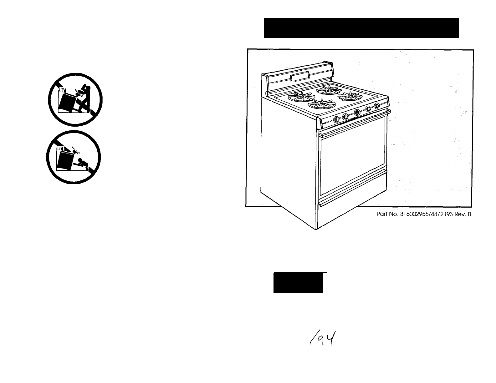
A WARNING
ALL RANGES CAN
TIP
INJURY TO PERSONS
COULD RESULT
INSTALL ANTI-TIP
DEVICE PACKED
WITH RANGE
SEE INSTALLATION
INSTRUCTIONS
Installation Instructions
IMPORTANT:
Read and save
these instructions
IMPORTANT:
Irrstaller: Leave Installation Instructions and
anti-tip bracket template with the
homeowner,
Homeowner; Keep Installation Instructions
and anti-tip bracket template for
future reference.
Save Installation Instructions for local
electrical inspector's use.
30" Freestanding
Gas
Range
h
Page 2
Before you start...
Proper installation is your responsibility. A
qualified technician must install this range.
Make sure you have everything necessary
for correct installation. It is the responsibility
of the installer to comply with the installation
clearances specified on the serial/rating
plate. The serial/rating plate is located
under the maintop.
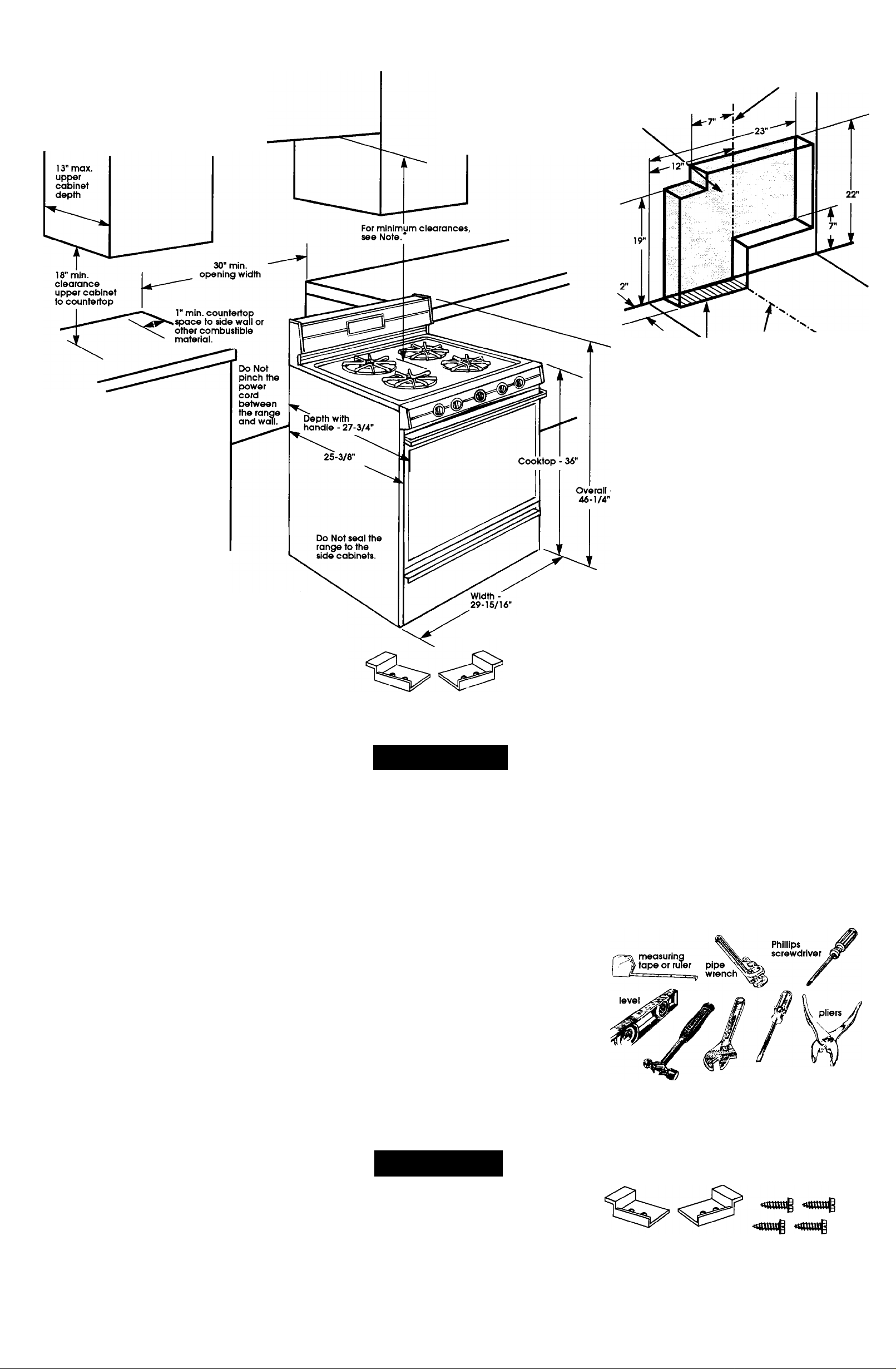
Note: 30" min. when bottom of
wood or metal cabinet is protected
by not less than 1/4" flame
retardant millboard covered with
not less than No.28 MSG sheet
steel, 0.015" stainless steel, 0.024"
aluminum or 0.020" copper.
36" min. clearance between the top
of the cooking platform and the
bottom of an unprotected wood or
metal cabinet.
Shaded area is
recommended area
for 120v outlet on
rear wall and area
for through-the-wall
connection of gas
pipe and shutoff
valve.
Electrical and gas dimensions
Center of range.
Grounded
electrical outlet
is required.
See Electrical
requirements.
ALL OPENINGS IN THE WALL
OR FLOOR WHERE THE
RANGE IS TO BE INSTALLED
MUST BE SEALED.
Important; Observe all
governing codes and
ordinances.
Check location where range will be
installed. The range should be located away
from strong draft areas, such as windows,
doors and strong heating vents or fans. The
range should be located for convenient use
in the kitchen. Recessed installations must
provide complete enclosure of the sides
and rear of range.
Proper gas
supply connection
must be available. See
Gas supply requirements.
that are shown
must be used. Given
dimensions provide 0" clearance.
Both anti-tip brackets MUST be installed.
Brackets attach to floor at back ot range to
hold both rear leveling legs. For detailed
instructions, see Panels B and C.
Cabinet
opening
dimensions
Recommended area
for through-the-floor
connection of pipe
and shutoff valve.
Center of
range.
Mobile Home Installation
The installation of this range must conform
to the Manufactured Home Construction
and Safety Standards, Title 24 CFR, Part
3280 (formerly the Federal Standard for
Mobile Home Construction and Safety,
Title 24, HUD Part 280) or when such
standard is not applicable, the Standard
for Manufactured Home Installation 1982
(Manufactured Home Sites, Communities
and Setups), ANSI Z225.1-NFPA 501 A, —
latest edition, or with local codes.
When this range is installed in a mobile
home, it must be secured to the floor.
Any method of securing the range is
adequate as long as it conforms to the
standards listed above.
Copies of the standards listed may be
obtained from:
* National Fire Protection Association
Batterymarch Park
Quincy, Massachusetts 02269
** American Gas Association
1515 Wilson Boulevard
Arlington, Virginia 22209
WARNING: If the information
in this manuai is not
foiiowed exactiy, a fire or
expiosion may resuit
causing property damage,
personai injury or death.
Do Not store or use
asoline or other
?
fl<
ammabie vapors and
iiquids in the vicinity of this
or any other appiiance.
■ WHAT TO DO iF YOU SMELL
GAS
• Do Not try to iight any
appiiance.
• Do Not touch any
eiectrical switch; Do
Not use any phone in
your buiiding.
• immediateiy coil your
gas suppiier from a
neighbor’s phone.
Foiiow the gas suppiier’s
instructions.
• if you cannot reach
your gas suppiier, caii
the fire department.
instaiiation and service
must be performed by a
quaiified instaiier, service
agency or the gas
supplier.
A WARNING
Fire Hazard
Do Not obstruct the flow of combustion
and ventilation air.
Personal Injury Hazard
To eliminate the risk of bums or fire,
avoid installing cabinet storage above
the cooking surface. If cabinets are
already installed, reduce the hazard of
reaching over a heated cooking
surface by installing a range hood.
The range hood should extend a
minimum of 5 inches out from the
bottom front of the cabinets.
Reaching over a heated cooking
surface could result in a serious burn.
Electrical Shock Hazard
It is the custonner’s responsibility:
• To contact a qualifié electrical
installer.
• To assure that the electrical
installation is adequate and in
conformance with Notional
Electrical Code, ANSI/NFPA
70 — latest edition*, and all local
codes and ordinances.
Failure to do so could result in
electrical shock or other personal
injury.
A CAUTION
Property Damage
• Contact a qualified floor covering
installer to check that the floor
covering can withstand heat at least
90”F above room temperature.
• Use an insulated pad or 1/4"
plywood under range if installing
range over carpeting.
Failure to do so may result in damage
to floor covering.
Tools and materials
needed for
installation:
• gas line shutoff valve
• L.P.-resistant pipe-
joint compound
• A.G.A. design-
certified flexible metal
connector (4-5 feet)
• flare union adapter
for connection to
pressure regulator
(1/2" NPTx 1^" or 3/4"
I.D.)
hammer
adjustable
wrench
• electric drill
wood floor:
3/16" drill bit
concrete/ceramic
floor:
3/16" carbidetipped masonry
drill bit
flat-blade
screwdriver or
5/16-inch nut driver
Parts supplied for installation:
2 anti-tip brackets
4 screws
Panel A
Page 3
Gas supply requirements
Observe all governing codes
and ordinances
Testing at 1/2 psI (gauge)
The range must be isolated from the gas
supply piping system by closing its individual
manual shutoff valve during any pressure
testing of the gas supply piping system at
test pressures equal to or less than 1 /2 psig
(3.5 kPa).
Adjust leveling .
legs so there is at least
1 /8 inch between
bottom of range and '
leveling legs.
i
1/8" min.
rr-n
T
A WARNING
Fire Hazard
• Range must be connected to a
regulated gas supply.
• L.P. gas supply must Not exceed a
pressure of 14" water column. This must
be checked by a qualified technician
before Installing the range.
• Do Not use an open flame to test for
leaks from gas connections.
• New, A.G.A. design-certified, flexible
gas line should be used when codes
permit.
Failure to follow these Instructions could
result In a fire, explosion or personal Injury.
This installation must conform with
local codes and ordinances. In the
absence of local codes, installations must
conform with American Nationai Standard,
Nationai Fuei Gas Code ANSI Z223.1 — latest
edition.**
B
seriai/rating piate are for elevations up to
2.000 feet. For eievations above 2,000 feet,
ratings are reduced at a rate of 4% for each
1.000 feet above sea levei.
A.G.A. for NATURAL and L.P. gases with
appropriate conversion. The seriai/rating
plate located under the cooktop has
information for the type of gas that can be
used. If this information does not agree with
the type of gas available, check with the
local gas supplier. See Panel C and back
cover for gas conversion instructions.
pipe to the range location. A smaller size
pipe on long runs may result in insufficient
gas supply. Pipe-joint compounds made for
use with L.P. gas must be used. With L.P.
gas, piping or tubing size can be 1 /2"
minimum. L.P. gas suppliers usually
determine the size and materials used on
the system.
codes permit, a
new A.G.A.design-certitied, 4 - 5 foot
long, 1 /2" or 3/4" I.D., flexible metal
appliance connector is recommended for
connecting this range to the gas supply line.
Do Not kink or damage the flexible tubing
when moving the range. A 1 /2-inch male
pipe thread is needed for connection to
pressure regulator female pipe threads.
MB to range
■ ■ The
supply line shall be
equipped with an approved shutoff valve.
This valve should be located in the same
room as the range and should be in a
location that allows ease of opening and
closing. Do Not block access to shutoff
valve.
line, a combination of pipe fittings must be
used to obtain an in-line connection to the
range. All strains must be removed from the
supply and fuel lines so range will be level
and in line.
Input ratings shown on the
This range is design-certified by
Provide a gas supply line of 3/4" rigid
If local
shutoff valve
“open” position
to gas supply
If rigid pipe is used as a gas supply
H The inlet pressure must be a
minimum of 1 inch above the set pressure of
the regulator, a maximum of 14 inches total
inlet pressure.
Set Pressure:
Natural Gas 4 Inches
L.P. Gas 10 Inches
I Line pressure testing:
Testing above 1/2 psi (gauge)
The range and its individual shutoff valve
must be disconnected from the gas supply
piping system during any pressure testing of
that system at test pressures greater than
1/2 psig (3.5 kPa).
Electrical
Requirements
A WARNING
Electrical Shock Hazard
• Electrical ground Is required on this
appliance.
• Do Not ground to a gas pipe.
• Do Not modify the power supply cord
plug. If It does not fit the outlet, have a
proper outlet Installed by a qualified
electrician.
• Do Not have a fuse In the neutral or
grounding circuit. A fuse In the neutral or
grounding circuit could result In an
electrical shock.
• Do Not use an extension cord with this
appliance.
• Check with a qualified electrician If you
are In doubt as to whether the appliance
Is properly grounded.
Failure to follow these Instructions could
result In a fire, electrical shock or other
personal Injury.
If codes permit and a separate
grounding wire is used, it is
recommended that a qualified
electrician determine that the
grounding path is adequate.
A 12CFvolt, 60-Hz, AC-only, 15-ampere, fused
elecfricai supply is required. A time-deiay
fuse or circuit breaker is recommended, it is
recommended that a separate circuit
serving oniy this appliance be provided.
Electronic ignition systems operate within
wide voltage limits, but proper grounding
and polarity are necessary. In addition to
checking that the outlet provides 120-volt
power and is correctly grounded, the outlet
must be checked by a qualified electrician
to see if it is wired with correct polarity.
The wiring diagram is found on a separate
sheet in the literature package. The wiring
diagram can also be found on the back of
the range.
Recommended grounding method
For personal safety, this appliance is
equipped with a power supply cord having
a 3-prong grounding plug. To minimize
possible shock hazard, the cord must be
plugged into a mating 3-prong, groundingtype wall receptacle, grounded in
accordance with the National Electrical
Code, ANSI/NFPA 70 — latest edition* and
all local codes and ordinances. (See Figure
1.) If a mating wall receptacle is not
available, it is the personal responsibility and
obligation of the customer to have a
properly grounded, 3-prong wall receptacle
installed by a qualified electrician.
3-prong
grounding
plug
■ 3-prong
grounding-type
power
supply
cord
grounding
prong
wall receptacle
Now start...
With range in kitchen.
I
protective film from range. Keep cardboard
shipping base under range. Remove oven
racks and shipping materials from inside
oven.
■ Remove shipping materials, tape and
A
WARNING
Personal Injury Hazard
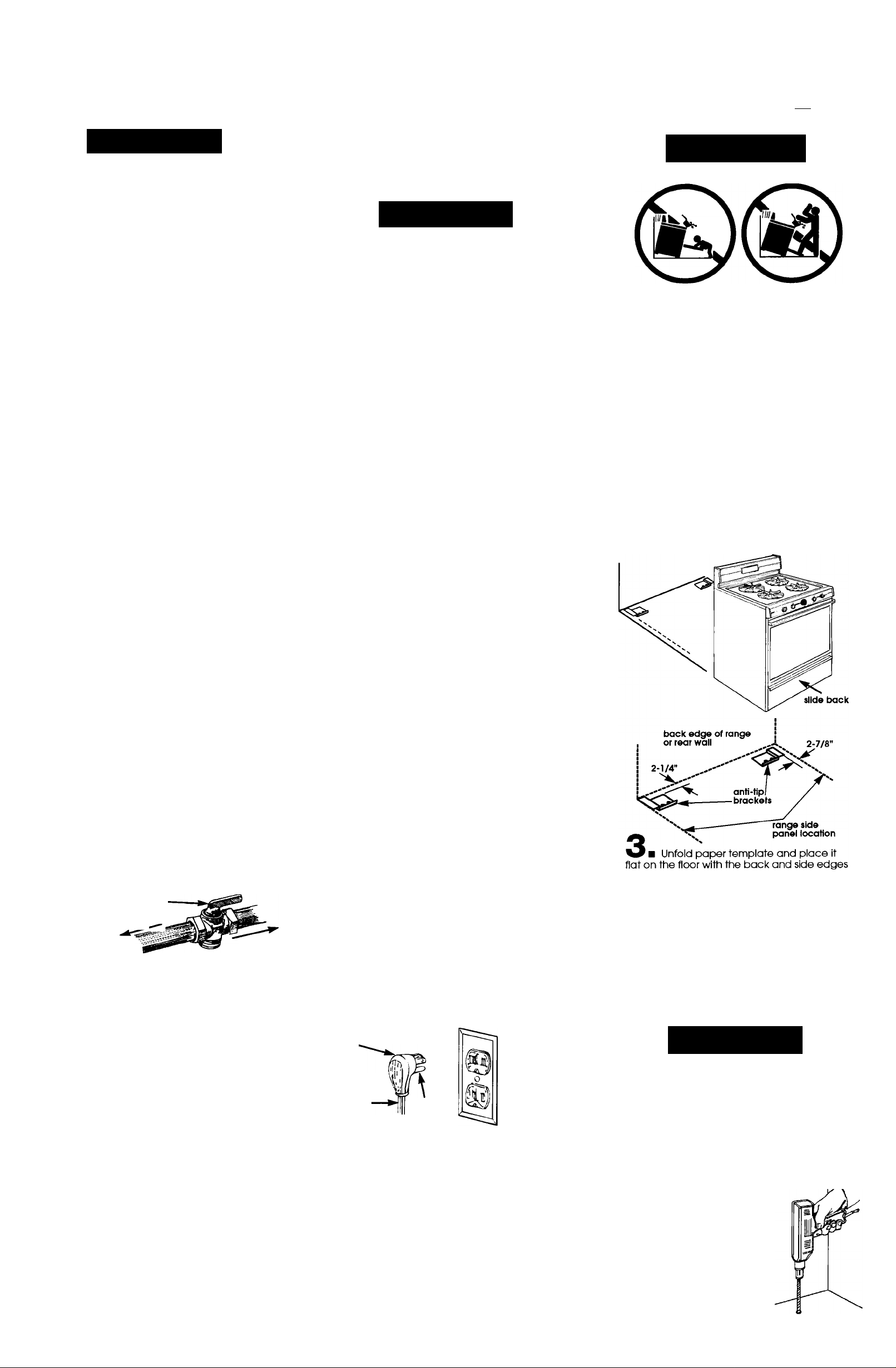
• To reduce the risk of tipping of the
appliance, the appliance must be
secured by properly Installed floormounted antl-tip brackets supplied with
the range.
• Save these Installation Instructions. If
range Is moved to a new location, the
antl-tip brackets must be removed and
reinstalled In the new location.
Electrical Shock Hazard
• Take special care when drilling holes
Into the floor. Electrical wires or
plumbing may be located beneath
floor.
• Locate the electrical circuits that could
be affected by the Installation of these
brackets and turn off power to these
circuits.
Failure to follow these Instructions may
result In electrical shock or other personal
Injury.
positioned exactly where the back and sides
of range wiii be iocated when instaiied.
if instaiiing range in a mobiie home, you MUST
secure range to floor. Any method of
securing range is adequate as iong as it
conforms to the standards iisted in the Mobiie
Flome instaiiation instructions, Panei A.
"T ■ Use a pencii to mark the mounting
screw hole iocations on the floor. Remove
template.
A
CAUTION
Property Damage
• Contact a qualified Installer for the best
procedure to drill mounting holes
through your type of floor covering.
• Before moving range across floor,
check that range Is on shipping base,
or slide range onto cardboard or
hardboard.
Failure to follow these Instructions may
result In damage to floor covering.
^3 ■ To mount antl-tip
bracket to wood floor, driii a
3/16" hoie, 1/2" deep, at each
mounting screw location.
To mount antl-tip bracket to
concrete or ceramic floor, use
a masonry drill bit to drill a
3/16" hole, 1 /2" deep, at each
mounting screw location.
Panel B
Page 4
16. 19.
Numbers
correspond
to steps.
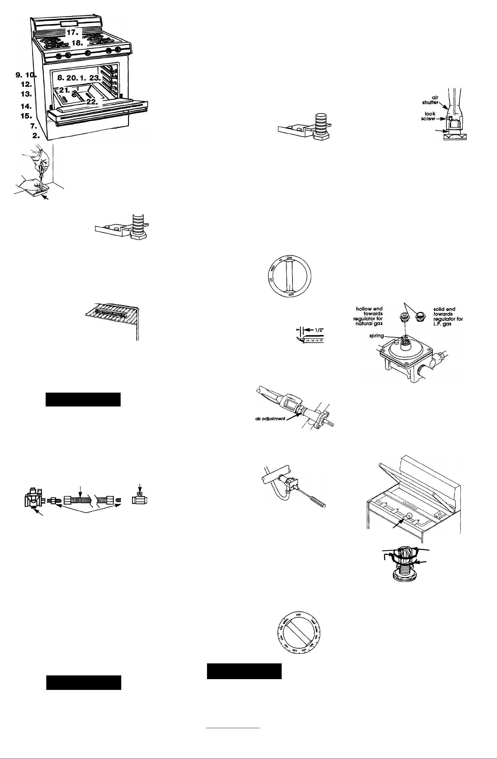
■ Place anti-tip
bracket on floor with turned-
up flange facing the front.
Line up holes in anti-tip
bracket with holes drilled in
floor. Use screws to attach
bracket to floor. Repeat
turned-up flange
■ ■ Remove shipping
base, cardboard or
hardboard from under
range. Remove storage
drawer. Carefully move range into position.
Grasp rear of range and carefully try to tip
range forward. If range tips forward, leveling
legs are NOT properly engaged in anti-tip
brackets. Remove and reposition braokets
so leveling legs will fit properly under end
flanges of brackets.
Place rack in
8
oven. Place level on
rack, first side to side;
then front to back to
check that range is
level. If range is not level, adjust legs up or
down. If needed, pull range forward until
rear leveling legs can be adjusted. Push
range back into position and check that
range is level.
Note: Oven must be level for satisfactory
baking conditions.
with right anti-tip bracket.
A WARNING
Fire Hazard
Do Not make connection too tight. The
regulator Is die cast.
Overtightening may crack the regulator,
resulting In a gas leak and possible fire or
explosion.
All connections must be wrenchtightened.
manual shutoff
flexible connector
pressure
regulator
■ Pull range forward to make gas
connections. Assemble the flexible
connector from the gas supply pipe to the
pressure regulator, located on the lower
right hand side on the back of the range, in
this order: shutoff valve, 1 /2" flare union
adapter, flexible connector, t /2" flare union
adapter. Seal all openings in floor or wall
wherever range is installed.
10
for use with Natural and L.P. gas to seal all
gas connections. If flexible connectors are
used, be certain connector is not kinked.
11b Open the shutoff valve in the
gas supply line. Wait a few minutes for gas to
move through the gas line.
1/2" flare union adapters
Use pipe-joint compound made
valve
A WARNING
Fire Hazard
Do Not use an open flame to test for leaks
from gas connections.
Checking for leaks with a flame may
result In a fire or explosion.
12
to test all gas connections for leaks. Bubbles
around connections wiii indicate a leak. If a
leak appears, shut off gas valve controls and
adjust connections. Then check
connections again. NEVER TEST FOR GAS
LEAKS WITH A MATCH OR OTHER FLAME.
Clean all detergent solution from range.
■ B Plug power supply cord into
grounded outlet.
Id
■ B Move range into final
position. Grasp rear of range and
carefully try to tip range forward
to check that both rear leveling
legs are engaged in anti-tip brackets.
15
Electronic Ignition System —
initial lighting and gas flame
adjustments.
When the cooktop control knob is turned to
"LITE" position, the system creates a spark to
light the burner. This sparking continues until
the control knob is turned to the desired
setting. When the oven control is turned to
the desired setting, a glow bar heats up
bright orange and Ignites the gas. No
sparking occurs and the glow bar remains
on while the burner operates.
16
operation of the cooktop
burners. Push in and turn
each control knob to "LITE"
position. The flame should light
within 4 seconds.
the “LITE” position after burner lights.
17
control knob to "HI" position. Check
each cooktop burner for proper flame.
The small inner cone should have a very
distinct blue flame approximately 1 /2"
long. The outer cone Is not as distinct as
the inner cone.
18.
need adjusting for proper
flame, remove burner
grates and carefully liff
up the maintop. Adjust
the air shutter to the
widest opening that will
produce a sharp blue flame that does not lift
or blow off of the burner. Repeat as
necessary with each burner.
19
the control knob to the
"LITE" position and then to
the "LO" position. The low
flame should be a
minimum, steady, blue
flame. To adjust the burner,
remove the control knob and turn the
adjustment screw in the center of the valve
stem. Check the adjustment by turning the
control knob from "HI" to "LO" several times.
The burner is properly adjusted when the low
flame remains steady and the burner does
not go out. Check each burner.
20.
oven screws at rear of oven bottom. Pull
oven bottom rear up and remove front of
oven bottom from oven front. Remove oven
bottom. Remove burner baffle.
Check the operation of the oven burner.
Push in and turn temperature control
knob counterclockwise to 300°F.
The oven burner should light In
50 - 60 seconds. This delay Is
normal. The oven safety valve
requires a certain time before it
will open and allow gas to flow.
• Do Not Insert any object Into the
• Do Not clean the area.
Failure to follow these Instructions could
result In product damage.
B Use a brush and liquid detergent
Turn power supply on to range.
Check the
Do Not leave the knob In
After burner lights, turn
If burners
Push in and turn
Remove oven rack. Remove
A
openings of the protective shield that
surrounds the Ignitor.
CAUTION
Product Damage
___________
21
for proper flame. This flame should
have a 1" long inner cone of bluish-
green, with an outer mantle of dark
blue, and should be clean and soft
in character. No yellow tips, blowing
or lifting of flame should occur.
22
needs to be adjusted,
locate the air shutter near
the center rear of the
oven burner. Loosen the
lock screw and adjust
the air shutter until the
proper flame appears.
Tighten screw.
Check the oven burner
If oven flame
orifice
hood
23. Replace the oven burner baffle,
oven bottom, oven racks and broiler drawer.
To get the most efficient use from
your new range, read your Use and
Care Guide. Keep instaiiotion
instructions and Guide close to the
range for easy reference.
Gas conversion
The serial rating plate, located under the
maintop, specifies the type of gas this range
was set to use. Conversion should be done
by a qualified installer.
Natural to L.P. gas
Aa Convert the pressure regulator. Do Not
remove the pressure regulator.
cap
1. Unscrew the cap from the pressure
regulator. Be sure spring stays in place.
2. Turn the cap over so the hollow end faces
outward.
3. Replace the cap of the regulator. The
letters L.P. should be visible on exposed
end of the cap.
Convert surface burner valves.
B.
cooktop
(shown in raised
position)
4 surface
burner
hoods
hood
NAT. GAS
increases gas
increases (lame size
(preset at factory for
rratural gas)
1. Lift and lock cooktop in up position.
2. Use 1 /2' wrench to turn hood clockwise
until snug (approximately 2-1/2 turns).
Do Not overtighten.
W ■ Convert oven burner.
1. Remove oven bottom hold-down screws
at rear of oven bottom. Pull up at rear,
and remove front of oven bottom from
oven front frame. Pull the oven bottom
straight out of the oven. Remove burner
baffle.
2. Use 1 /2" wrench to turn the hood
clockwise (approximately 2-1/2 turns), until
snug against the pin. Do Not overtighten.
3. Turn thermostat control knob to 300°F. The
oven burner flame should be steady and
approximately 1" long with no yellow or
orange tips.
L.P. GAS
decreases gas
decreases flame size
Panel C
Page 5
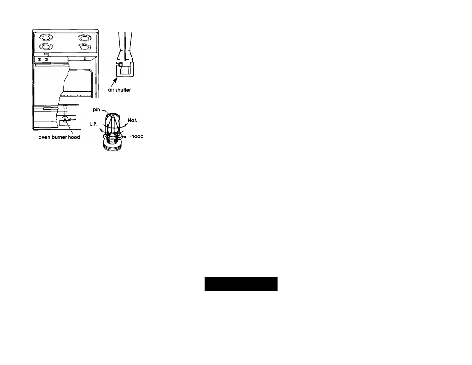
4. If air shutter needs adjusting, loosen air
shutter set screw and adjust to obtain
proper flame. This will normally be
completely open for L.P. gas. Tighten air
shutter set screw.
5. Replace oven baffle and oven bottom.
L.P. to Natural gas
Converting to natural gas should be done by
a qualified Installer.
Use a wrench to remove cap from pressure
regulator. Turn cap over so that the "Nat."
side is up and replace cap and gasket on
regulator.
Cooktop orifice hoods and oven orifice
hood need to be loosened 2 to 2-1/2 turns
counterclockwise to allow for proper gas
flow. The flame adjustment for cooktop
burners and oven burner would be the same
as described in the installation steps (see
Panel C). ■
Part No. 316002955/4372193 Rev, B
If range does not operate...
• Check that the circuit breaker is not
tripped or the house fuse blown,
• Check that the power supply cord is
plugged into wall receptacle.
• Check that the gas supply is turned on.
NOTE: Refer to Use and Care Guide for
operating instructions and cleaning
instructions.
For cleaning and maintenance...
If removing the range is necessary for
cleaning or maintenance, shut off gas
supply to the range. Disconnect the gas and
electric supply.
If the gas or electrical supply is inaccessible,
lift the range slightly at the front and pull the
range out away from the wall. Pull the range
out only as far as necessary to disconnect
the gas and electric supply lines.
Remove the range to complete cleaning or
maintenance.
Move range back into operating position.
Level the range. Connect gas line to range
and check for leaks. Plug electric power
supply cord into outlet. Make sure that rear
legs are engaged in anti-tip bracket.
A WARNING
Personal Injury Hazard/Product Damage
Do Not step, lean or sit on the range or the
door or drawers of the range.
Failure to follow this Instruction could result
In personal Injury and/or product damage.
Benton Harbor, Michigan 49022
If yoti need assistance...
Check your Use and Care Guide for a toll
free number to call or call the dealer from
whom you purchased this appliance. The
dealer is listed in the Yellow Pages of your
phone directory under “Appliances —
Household — Major — Service & Repair."
When you call, you will need the range
model number and serial number. Both
numbers can be found on the serial/rating
plate located under the maintop.
Printed on recycled paper.
10% post consumer waste/
0
50% recovered materials.
Printed in U.S.A.
 Loading...