


D
INSTALLATIONSANLEITUNGEN
Mindestabstand über der Kochfläche: 50 cm bei Elektroplatten, 65 cm bei Gasmulden oder gemischt
betriebenen Kochfeldern. Schreiben die Installationsanweisungen des Gaskochfelds einen g r ößeren
Abstand vor, ist dieser natürlich zu beachten. Folgen Sie bei der Installation der Nummerierung
(123.....). Schließen Sie das Gerät erst nach seiner kompletten Installation an das Stromnetz an.
Achtung! Kontrollieren Sie, ob das Abluftrohr und die Befestigungsschellen mitgeliefert wurden.
Andernfalls sind sie separat zu beziehen.
Aufgrund des schweren Gewichtes sind mindestens zwei oder noch mehr Personen zur Beförderung
und Installation der Abzugshaube erforderlich.
GB
SCHEDA INSTALLAZIONE
Minimum height above cooker: 50 cm for electric cookers, 65 cm for gas or mixed cookers. If the
installation instructions for a gas cooker specify a greater distance, then this distance must be
observed. To install, follow steps (123.....). Do not connect the hood to the electrical power
supply until installation is completed. Warning! Check whether the exhaust pipe and clamps are
provided. If not, they must be purchased separately.
Excessively heavy product; hood handling and installation must be carried out by two or more
persons.
F
FICHE D'INSTALLATION
Distance minimale par rapport à la cuisinière : 50 cm minimum dans le cas d'une cuisinière électrique,
65 cm dans le cas d'une cuisinière à gaz ou mixte. Si les instructions d'installation du dispositif de
cuisson à gaz indiquent une distance supérieure, il est nécessaire de la respecter. Pour le montage,
suivez la numérotation (123.....). Ne branchez pas l'appareil tant que l'installation n'est pas
terminée. Attention ! Vérifiez si le conduit d'évacuation et les colliers de fixation sont fournis avec
l'appareil. Dans le cas contraire, les acheter.
Appareil excessivement lourd ; la manutention et l'installation de la hotte doivent être effectuées par
deux personnes ou plus.
NL
INSTALLATIEKAART
Minimumafstand tot het kooktoestel: 50 cm bij elektrische kooktoestellen, 65 cm bij kooktoestellen
op gas of gemengd. Als de installatie-instructies van het kooktoestel op gas een grotere afstand
aangeven, moet hiermee rekening gehouden worden. Volg voor de montage de nummering
(123.....). Geef het apparaat geen stroom totdat de installatie geheel voltooid is. Let op!
Controleer of de afvoerpijp en de klembanden bijgeleverd zijn. Zo nie t, dan moeten ze apart worden
aangeschaft.
Aangezien dit apparaat zwaar is, dient het door minstens twee of meer personen verplaatst en
geïnstalleerd te worden.
5019 418 33087

E
FICHA DE INSTALACIÓN
Distancia mínima desde los quemadores: 50 cm en caso de cocinas eléctricas y 65 cm en caso de
cocinas a gas o mixtas. Si en las instrucciones de instalación de la placa de cocina a gas se especifica
una distancia mayor respecto a la indicada, es necesario tenerlo en cuenta. Para el montaje, siga la
numeración (123...). No conecte el aparato a la corriente eléctrica hasta que la instalación esté
completamente finalizada. ¡Atención! Compruebe si el tubo de descarga y las abrazaderas de fijación
se suministran de serie. En caso contrario, tiene que comprarlos por separado.
Producto con peso excesivo; la campana extractora ha de ser transportada e instalada por dos o más
personas.
P
FICHA DE INSTALAÇÃO
Distância mínima dos fogões: 50 cm no caso de fogões eléctricos, 65 cm no caso de fogões a gás ou
mistos. Respeite as instruções de instalação do dispositivo de cozedura a gás se estas especificarem
uma distância superior à indicada. Para a montagem siga a numeração (123.....). Não ligue o
aparelho à corrente eléctrica enquanto a instalação não estiver concluída. Atenção! Verifique se o
tubo de descarga e as braçadeiras de fixação foram fornecidos com o aparelho. Caso contrário, deverá
adquiri-los à parte.
Produto com peso excessivo. A movimentação e a instalação do exaustor devem ser feitas por pelo
menos duas ou mais pessoas.
I
SCHEDA INSTALLAZIONE
Distanza minima dai fuochi: 50 cm in caso di cucine elettriche, 65 cm in caso di cucine a gas o miste.
Se le istruzioni di installazione del dispositivo di cottura a gas specificano una distanza maggiore
rispetto a quella specificata, bisogna tenerne conto. Per il montaggio seguire la numerazione
(123.....). Non dare corrente all’apparecchio finché l’installazione non è totalmente completata.
Attenzione! Verificare se il tubo di scarico e le fascette di fissaggio sono forniti a corredo. In caso
contrario, vanno acquistati a parte.
Prodotto dal peso eccessivo, la movimentazione e installazione della cappa deve essere fatta da
almeno due o più persone.
GR
ΚΑΡΤΕΛΑ ΕΓΚΑΤΑΣΤΑΣΗΣ
Ελάχιστη απόσταση από τις εστίες: 50 cm σε περίπτωση ηλεκτρικών εστιών και 65 cm σε
περίπτωση εστιών αερίου ή µικτού τύπου. Εάν οι οδηγίες εγκατάστασης της εστίας αερίου
συνιστούν µεγαλύτερη απόσταση, σε σχέση µε εκείνη που έχει οριστεί, εφαρµόστε τις σχετικές
οδηγίες. Για την τοποθέτηση ακολουθήστε την αρίθµηση (123.....). Μην τροφοδοτείτε µε
ηλεκτρικό
ότι ο σωλήνας απαγωγής και τα κολάρα στερέωσης διατίθενται µε τον εξοπλισµό. Σε αντίθετη
περίπτωση πρέπει να τα προµηθευτείτε χωριστά.
Προϊόν µε µεγάλο βάρος. Η µετακίνηση και η εγκατάσταση του απορροφητήρα πρέπει να γίνει
τουλάχιστον από δύο ή περισσότερους ανθρώπους.
ρεύµα τη συσκευή πριν την ολοκλήρωση της εγκατάστασης. Προσοχή! Βεβαιωθείτε
5019 418 33087
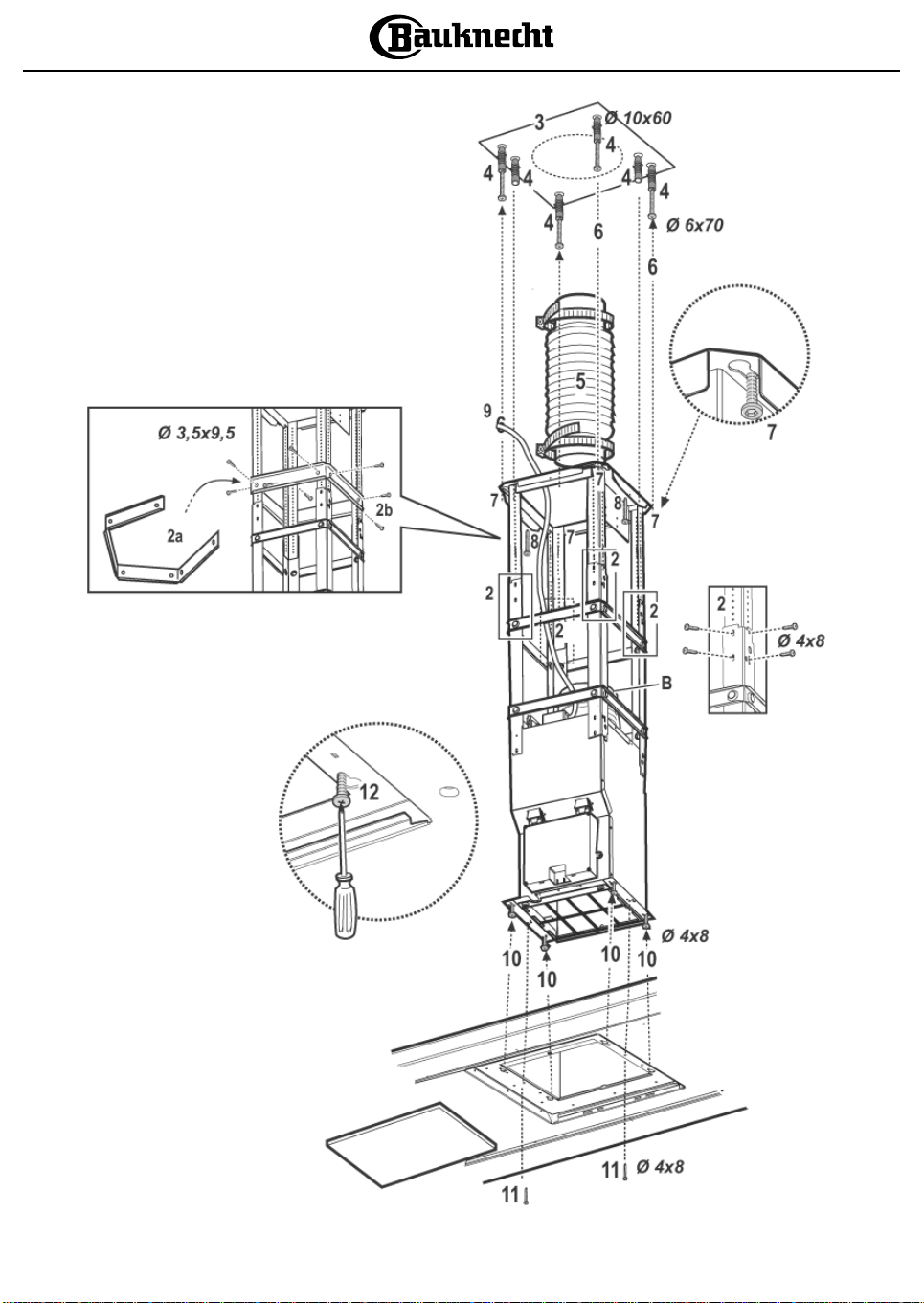
Abb. 1
Fig. 1
Afb. 1
Fig. 1
Εικ. 1
5019 418 33087
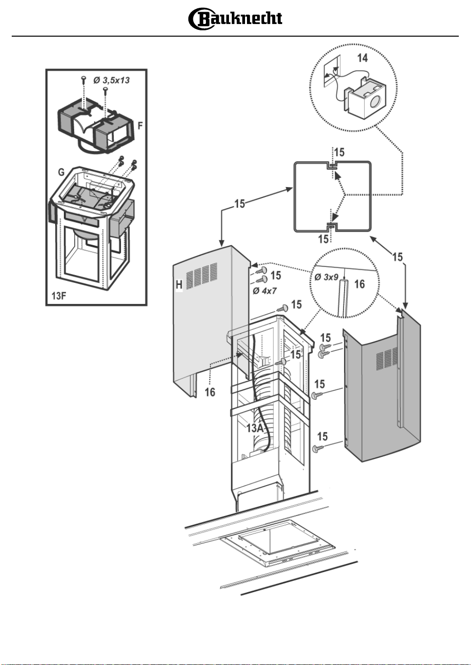
Abb. 2
Fig. 2
Afb. 2
Fig. 2
Εικ. 2
5019 418 33087
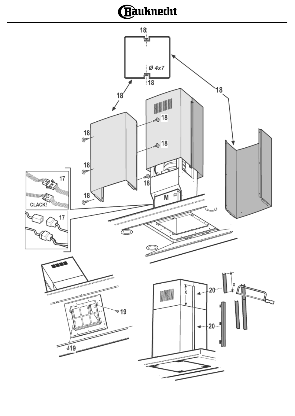
Abb. 3
Fig. 3
Afb. 3
Fig. 3
Εικ. 3
5019 418 33087

INSTALLATION - ASSEMBLY INSTRUCTIONS
Expansion plugs are provided to secure the hood to most types of walls/ceilings However, a qualified technician is needed to
make sure that the plugs are suitable for your wall/ceiling. The wall/ceiling must be strong enough to take the weight of the
hood.
Disconnect the power supply at the home main switch during electrical connections.
Remove the perimeter extraction panel and the grease filter/s (see the maintenance instructions for how to do this).
FIG. 1
1. Adjust the extension of the hood support structure to regulate the final height of the hood. Bear in mind that with installation completed
the minimum distance between the hood and the cook-top must comply with the indications given on the first page of this booklet.
2. Fix the two sections of the structure using a total of 16 screws (4 at each corner).
Reinforce the top section, if it is of more than minimum extension, by fittin g 1 or 2 brackets (according to the number supplied).
To do this, proceed as follows:
a. Extend the fixing brackets slightly so that they will fit around the outside of the structure.
b. Position the reinforcement bracket immediately over the point at which the two sections of the structure are joined, and fix with a total
of 8 screws (2 at each corner).
Fix the second reinforcement bracket, if there is one, at a position equidistant to the first reinforcement bracket and the top side of the
truss, fix it using 8 screws (2 at each corner).
Note: when positioning and fixing the reinforcement bracket/s, check that they will not get in the way when fixing the exhaust pipe
(extractor version) or the deflector (filter version).
3. Place the ceiling hole diagram directly above the cooktop (the centre of the diagram must match the centre of the cooktop and the edges
must be parallel to the sides of the cooktop. The side of the diagram with the wording FRONT corresponds to the control panel side).
Prepare the electrical connection.
4. Drill as shown (6 holes for 6 wall plugs - 4 plugs for hooking), screw the 4 outer screws leaving a space of about 1 cm between the screw
head and the ceiling.
5. Fit an exhaust pipe inside the truss and connect it to the collar of the motor compartment (exhaust pipe and clamps are not provided).
6. Hook the truss to the 4 screws (see step 4).
CAUTION! The side of the truss with connection box corresponds to the side of the control panel with hood assembled.
7. Tighten the 4 screws.
8. Insert and tighten another 2 screws in the remaining free ho les for secure fixing.
9. Carry out the electrical connection to the mains power supply; only turn on the power supply with assembly completed.
10. Hook the hood to the truss, checking for perfect hooking - to hook the hood to the truss partially screw 4 screws (also see step 12).
Warning! In certain models hooking may be temporarily prevented by the presence of screws; if this is the case, remove the screws,
hook up the hood and then REPLACE THE SCREWS!
11. Fixing the hood to the truss with two screws, will also facilitate centering of the two parts.
12. Firmly tighten the 4 screws fixing the truss to the hood.
FIG. 2
13. In the extractor version (13A), connect the other end of the exhaust pipe to the domestic exhaust ducting system.
In the filter version (13F), fit the deflector F on the truss and fix it to the bracket using 4 screws, then connect the exhaust pipe to the collar
on the deflector.
14. Fit the nuts with fixing hooks supplied inside the top and bottom sections of the flues at the rectangular slots; a total of 14 nuts must be fitted.
15. Join the two top sections of the flue to cover the truss so that one of the slots on the secti on s is situated on the same side of the control
panel and the other on the opposite side.
Screw the two sections with 8 screws (4 each side - see the plan diagram for joining the two sections).
16. Fix the top flue assembly to the truss, near the ceiling, with two screws (one each side).
FIG. 3
17. Carry out electrical connection of control panel and bulbs.
18. Join the two bottom sections of the flue covering the truss using 6 screws (3 each side - also see the plan diagram for joining the two
sections).
19. Insert the bottom section of the flue in the special seat to completel y cover the motor compartment and electrical connection box, andfix
the hood with two screws from the inside (certain models only).
20. Hook the 2 tabs (supplied, which can be identified by their hooks).
The wider and deeper tabs are to be used for the top flue, and must be cut to measure.
Refit the grease filter and the perimeter extraction panel, connect the hood to the power supply, and wait for the control
electronics to carry out the calibration necessary for proper operation of the control panel (all pushbuttons will flash during
calibration).
5019 418 33087
GB
D F NL E
P I GR

1. Control panel.
2. Grease filter.
3. Halogen bulbs.
4. Steam deflector.
5. Telescopic flue.
6. Extraction panel.
PRODUCT DESCRIPTION SHEET
5
3
1
6
2
3
4
Fig. 4
3
Control panel
To select the hood functions you only have to touch the controls lightly.
They are screen printed at the centre of the glass on the front of the hood.
ABCDEF
A
B
Motor ON/OFF switch (stand by) - Electronics OFF
MOTOR OFF
Press briefly to turn the motor off.
ELECTRONICS ON/OFF
Press for more than 3 seconds to disable the hood control electronics.
Note: it is still possible to turn the lights on and off.
This function may be useful when cleaning the product.
To turn the electronics back on again, simply repeat the operation.
Low speed selection button (suction power) and Timer ON/OFF button.
After selecting the speed, press again for more than 2 seconds to set the timer (the button starts to flash).
The hood will turn off after 20 minutes.
3
C
D
E
F
Medium speed selection button (suction power) and Timer ON/OFF button.
After selecting the speed, press again for more than 2 seconds to set the timer (the button starts to flash).
The hood will turn off after 15 minutes.
High speed selection button (suction power) and Timer ON/OFF button.
After selecting the speed, press again for more than 2 seconds to set the timer (the button starts to flash).
The hood will turn off after 10 minutes.
Intensive speed selection button (suction power) - duration 5 minutes - and Timer ON/OFF button.
After selecting the speed, press again for more than 2 seconds to set the timer (the button starts to flash).
The hood will turn off after 5 minutes.
Light ON/OFF button
In the event of any malfunction, before contacting the service department, try disconnecting the appliance from the
power supply for at least 5 sec. by removing the plug, then re-connecting the plug and waiting approximately 15 seconds
(the time required to perform recalibration of the controls) before trying again.
If the fault persists, contact an authorised service centre.
5019 418 33087
GB
D F NL E
P I GR
Maintenance
ALWAYS disconnect the hood from the mains before performing
maintenance.
Clean the perimeter extraction panel as often as the grease filter.
Use a cloth and a mild liquid detergent.
Never use abrasive substances.
Wash the grease filter and the carbon filter in a dishwasher once a
month, at the highest possible temperature, using normal
dishwasher detergent.
It is recommended to wash the filters on the their own.
After washing, reactivate the carbon filter by drying it in the oven
at 100° C for 10 minutes. Fit a new carbon filter every 3 years.
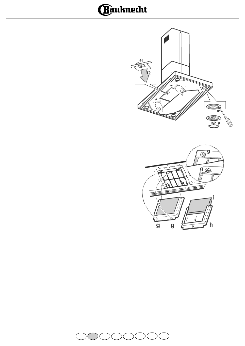
Remove the perimeter extraction panel - Fig.5:
Warning! Hold the panel with both hands when you remove
it or replace it, to prevent it from falling and causing damage
or injury.
Pull the panel (FRONT SIDE) firmly downwards and disconnect it
from the rear hinges.
Fitting: The panel must be hooked up at the rear and snap-fitted
at the front into the hinges provided for this purpose on the
surface of the hood.
Warning! Always check to ensure that the panel is firmly
fixed in place.
Remove the grease filters - Fig. 5: to do so, (after removing the
perimeter extraction panel) push the spring release handle
backwards (f5) then remove the filter downwards (f6).
Fitting: reverse the above procedure.
Replacing bulbs - Fig. 5:
1. Use a small screwdriver or any other suitable tool to prise off
(m) the lamp cover (p).
2. Remove the burnt-out bulb. Replace using 12V - 20W max -
G4 max halogen bulbs only taking care not to touch them with
your hands.
3. Close the lighting unit (snap-on).
Fig. 5
Fitting (Removing) the carbon filter - Fig. 6:
1. Remove the perimeter extraction panel.
2. Remove the grease filter.
3. Turn the side knobs 90° and then remove the filter holder (g).
4. Insert (or remove, if washing or replacing) the carbon filter (i)
inside the filter holder frame (h).
5. Refit the carbon filter frame, the grease filter and the perimeter
extraction panel in their proper places.
5019 418 33087
GB
D F NL E
Fig. 6
P I GR

PROTECTING THE ENVIRONMENT
1. Packaging
Packaging materials are 100% recyclable and are marked with the
recycling symbol . Dispose of the appliance in conformity with
local environmental regulations. Packaging materials (plastic bags,
polystyrene, etc.) can be dangerous for children and should be kept
well out of their reach.
2. Product
This appliance is marked in compliance with European Directive
2002/96/EC on Waste Electrical and Electronic Equipment (WEEE).
By ensuring that this appliance is scrapped suitably, you can help
prevent potentially damaging consequences for the environment and
health.
The symbol on the appliance or accompanying documentation
indicates that this product should not be disposed of as unsorted
municipal waste but must be taken to a collection point for the
treatment of WEEE.
Disposal must be carried out in accordance with local environmental
regulations for waste disposal.
For further information on the treatme nt, recovery and recycling of this
appliance, contact your competent local authority, the collection service
for household waste or the shop where you purchased the appliance.
PRECAUTIONS AND GENERAL
RECOMMENDA TIONS
WARNING!
• The appliance is not intended for use by young children or
persons with restricted physical, sensory or mental
abilities or without experience and knowledge of the
appliance, unless they are under the supervision or
instruction of a person responsible for their safety.
• Young children should be supervised to ensure that they do
not play with the appliance.
1. Do not connect the appliance to the mains power supply until
installation has been fully completed. Always disconnect the hood
before cleaning or carrying out maintenance by unplugging it or
switching off the power supply .
2. Do not flambé food under the hood. Naked flames could cause
afire.
3. Do not leave pans unattended when frying. Cooking o il can
catch fire.
4. Regular cleaning and maintenance is essential to correct functioning
and good performance. Regularly remove dirt deposits. Regularly
clean or replace filters. Never use flammable materials as hoses for
extracted air .
5. If the hood is used together with other appliances powered by gas
or other fuels, ambient negative pressure must not exceed 4Pa
(4 x10⁻⁵ bar). For this reason, make sure the room is adequately
ventilated.
6. Exhaust air must not be conveyed through the same flue used by
the heating system or other appliances powered by gas or other
fuels.
7. The room must be adequately ventilated when the hood is used
together with appliances powered by gas or other fuels.
8. When replacing the bulbs, first ensure that they are cold.
9. The discharge air must not be ducted to a flue used for removing
fumes produced by appliances using gas or other fuels, but must
have a separate outlet. All national regulations on air discharge
must be observed.
10. The hood is not a shelf. It must not be overloaded or used to
carry objects
Note: always wear work gloves for all installation and maintenance
operations.
Electrical connections
The mains power supply must correspond to the voltage indicated
on the appliance rating plate located inside the hood. If it is fitted
with a plug, connect the hood to a power socket that complys with
applicable standards and is in an easily accessible location. If it is not
fitted with a plug (direct connection to the power supply) or if the
socket is not in an easily accessible location, fit a two-pole switch in
compliance with regulations, to ensure complete disconnection from
the mains voltage in conditions of category III overvoltage, according
to the rules for proper installation.
WARNING: Before reconnecting the hood circuit to the
mains power supply and checking correct operation, make
sure the power cable is correctly fitted and that it was NOT
crushed in the housing during installation.
Cleaning the hood
Warning! Failure to remove oil and grease (at least once a month) could
lead to fire.
Use a soft cloth with a neutral detergent. Never use abrasive
substances or alcohol.
Before using the hood
Please read these instructions carefully and keep them for future
reference, in order to ensure best use of your hood.
Packaging materials (plastic bags, polystyrene, etc.) can be dangerous
for children and should be kept well out of their reach.
Make sure the hood has not been damaged during transport.
Declaration of conformity
This product has been designed, manufactured and sold in
compliance with the following standards:
- safety objectives of "Low Vo ltage" Directive 73/23/EEC
- protection requirements of “EMC” Directive 89/336/EEC
amended by Directive 93/68/EEC.
Troubleshooting guide
The hood does not work:
• Is the plug properly inserted in the power socket?
• Is there a power failure?
The hood is not extracting efficiently:
• Is the right speed selected?
• Do the filters need cleaning or replacing?
• Are the air outlets blocked?
The light does not work:
• Does the bulb need replacing?
• Is the bulb correctly fitted?
AFTER-SALES SERVICE
Before calling the After-sales Service
1. Check if you can fix the problem yourself (see ”Troubleshooting
guide”).
2. Switch the hood off and then on again to check if the problem
has gone.
3. If the problem persists, contact the After-sales Service.
Specify:
•the nature of the problem,
• the model of hood, stated on the data plate inside the hood,
accessible by removing the grease filters.
• your full address,
• your telephone number and area code.
• the service code (the number appearing below the word
SERVICE on the data plate inside the hood behind the
grease filter).
If any repairs are needed, contact an authorized Service Centre
(to ensure that only original spare parts are used and that repairs are
made correctly).
Failure to comply with these instructions may compromise the safety
and quality of the product.
5019 418 33087
 Loading...