

Whirlpool AKM 624/NB INSTRUCTION FOR USE
AKM 624 PRODUCT DESCRIPTION SHEET
GB
DE AT BE FR NL ES IT
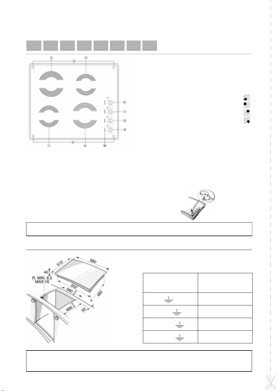
Radiating cooking zone Ø 145
1.
Radiating cooking zone Ø 210
2.
Haloring cooking zone Ø 145
3.
Haloring cooking zone Ø 180
4.
Residual heat indicator
5.
Front left cooking zone control knob
6.
Rear left cooking zone control knob
7.
Rear right cooking zone control knob
8.
Front right cooking zone control knob
9.
Power indicators
10.
•
To use the hob, turn the knob(s) clockwise and set
it/them to the required power.
• To turn the hob off, turn the knob(s) back to
position “0”.
• This model is provided with luminous indicators
situated near the knobs (6 lamps for each control
knob). These lamps indicate the progression of the
power selected.
• The hob is fitted with residual heat indicators.
These light up when the cooking zones reach
temperatures that could cause burns. These
indicators remains alight after the cooking zones
are switched off, and turn off only when the zones
are no longer hot enough to be dangerous.
• A special device allows the knobs to be raised by about
1 cm, for cleaning the cooking zones below. After
cleaning, return the knob to the original position.
Important:
To avoid permanently damaging the glass-ceramic top,
do not use:
- Pots with bottoms that are not perfectly flat.
- Metal pots with enamelled bottom.
Clean the cooktop frame with warm water and neutral solution only.
Do not use corrosive and/or abrasive substances which could damage the enamelled surface.
DIMENSIONS OF THE COOKTOP AND WORKTOP
ELECTRICAL CONNECTION
Supply voltage
230 V ~
230 V 3 ~ +
Conductors
(number and size)
3 X 2.5 mm
4 X 1.5 mm
2
2
5019 319 60561
400 V 3N ~ +
400 V 2N ~ +
5 X 1.5 mm
4 X 1.5 mm
2
2
 Loading...