

Whirlpool AKF 616 IX, AKF 619 IX, AKF 615 IX, AKF 618 IX INSTRUCTION FOR USE
AKF 618 / AKF 619 PRODUCT DESCRIPTION SHEET
IT
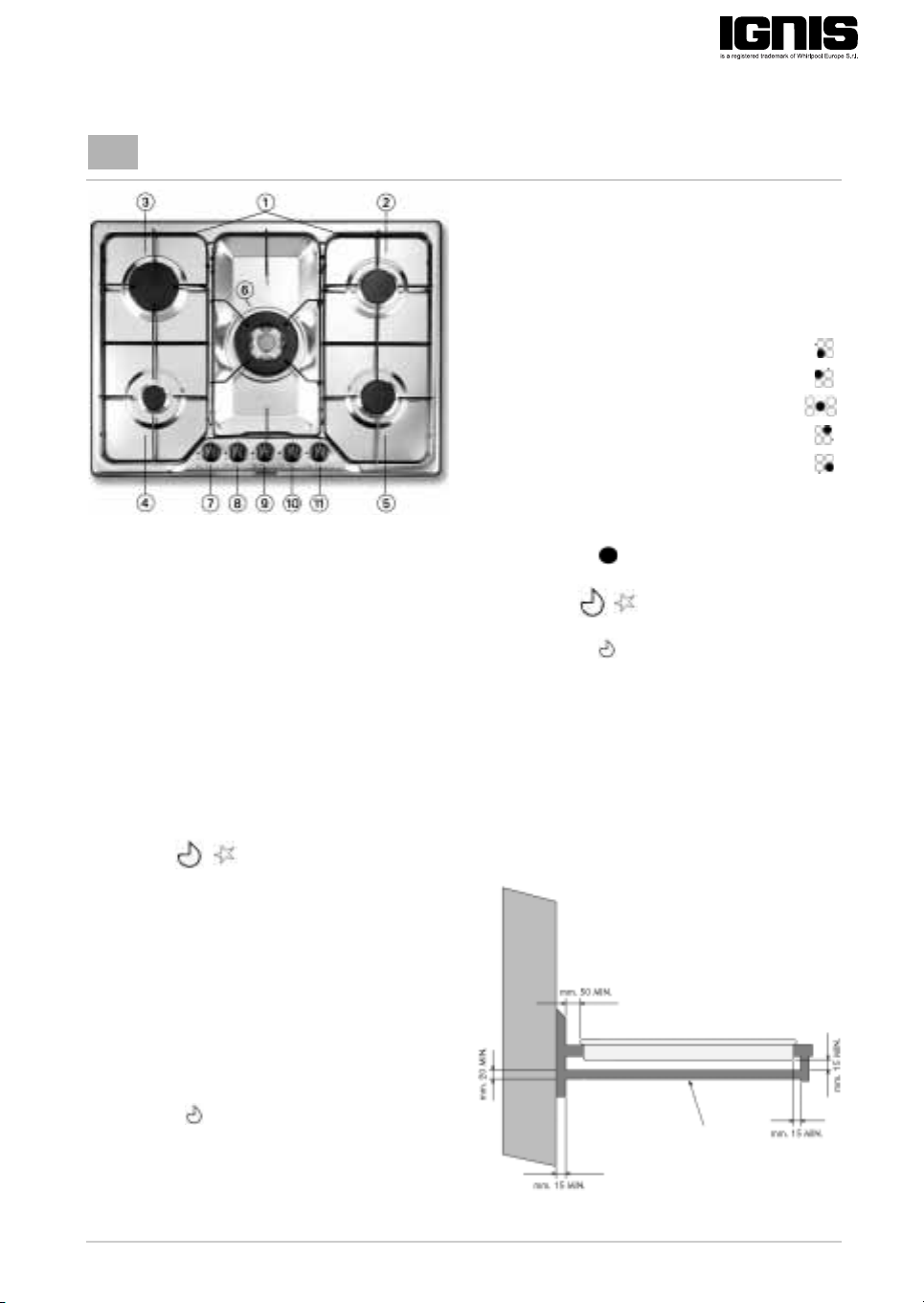
1.
Removable grids
2-5.
Medium burners
3.
Large burner
4.
Auxiliary burner
6.
Tr ip le cr o w n b ur ne r
7.
Front left burner control knob
8.
Rear left burner control knob
9.
Central burner control knob
10.
Rear right burner control knob
11.
Front right burner control knob
Symbols
Operation of burners with safety
device and electric ignition
To light one o the burners:
• Press the relative knob and turn it anticlockwise to the large flame and star
setting .
• At the same time, hold the knob down until
the burner ignites.
• After the burner has ignited, keep the knob
pressed for about 10 seconds.
• Release the knob.
If the burner does not ignite, repeat the operation.
Note:
Should particular local conditions of the
delivered gas make ignition of the burner
difficult, it is advisable to repeat the operation
with the knob turned to the small flame
setting .
Shaded
circle
Large flame
and star
Small flame
The burner safety device shuts off the gas
supply to the burner if the flame goes out
accidentally (because of a sudden draught, an
interruption in the gas delivery, boiling over of
liquids, etc.).
The separator panel, positioned beneath the
cooktop at a minimum distance of 20 mm,
must be sealed.
Tap cl osed
Maximum opening/delivery
and electric ignition
Minimum opening or
reduced delivery
Insert a wooden panel at
least 20 mm thick under the
hob, at a distance of at least
15 mm from the cooking
hob bottom.
5019 519 66008
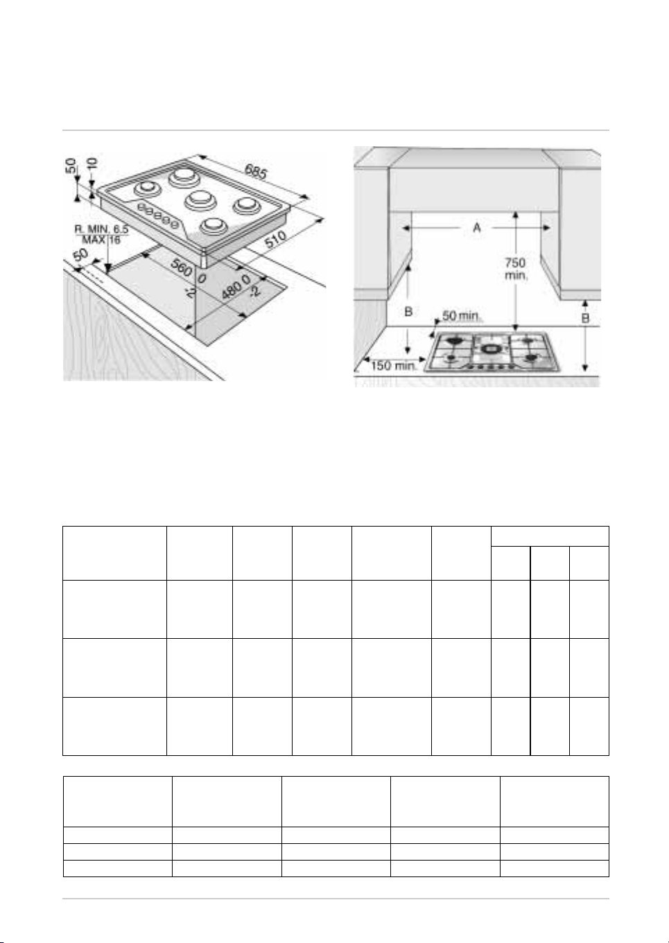
DIMENSIONS OF COOKING HOB AND WORKTOP (mm)
NOTES: If the distance “A” between the wall cabinets is between 600 mm and 680 mm,
the height “B” must be at least 520 mm.
If the distance “A” between the wall cabinets is greater than the width of the
hob, the height “B” must be a minimum of 400 mm.
Before installing a hood above the hob please refer to the hood instructions,
which specify the correct distance.
INJECTORS TABLE CATEGORY II2H3+
Typ e o f g as us ed Typ e o f
NATURAL GAS
(Methane) G20
LIQUID
PETROLEUM GAS
(Cylinder) G30
LIQUID
PETROLEUM GAS
(Cylinder) G31
Typ e o f gas
used
G20 20 mbar 5 gas 11 1048 22
G30 28-30 mbar 5 gas 11 799 22
G31 37 mbar 5 gas 11 799 22
burner
triple crown
rapid
semi-rapid
auxiliary
triple crown
rapid
semi-rapid
auxiliary
triple crown
rapid
semi-rapid
auxiliary
Appliance model Total rated heat
Injector
marking
100/mm
141
129
101
77
94
87
66
50
94
87
66
50
Rated heat
capacity
kW
3.50
3.00
1.75
1.00
3.50
3.00
1.75
1.00
3.50
3.00
1.75
1.00
capacity
kW
Rated
consumption
333 l/h
286 l/h
167 l/h
95 l/h
254 g/h
218 g/h
127 g/h
73 g/h
254 g/h
218 g/h
127 g/h
73 g/h
Total rated
consumption
Reduced
heat
capacity
kW
1.50
0.80
0.50
0.50
1.50
0.80
0.50
0.50
1.50
0.80
0.50
0.50
ELECTRIC SUPPLY: 230 V ~ 50 Hz
Gas pressure mbar
min. rat. max.
17 20 25
20 28-30 35
25 37 45
Air necessary (m3)
for the combustion
3
of 1 m
of gas
 Loading...