

Page 1
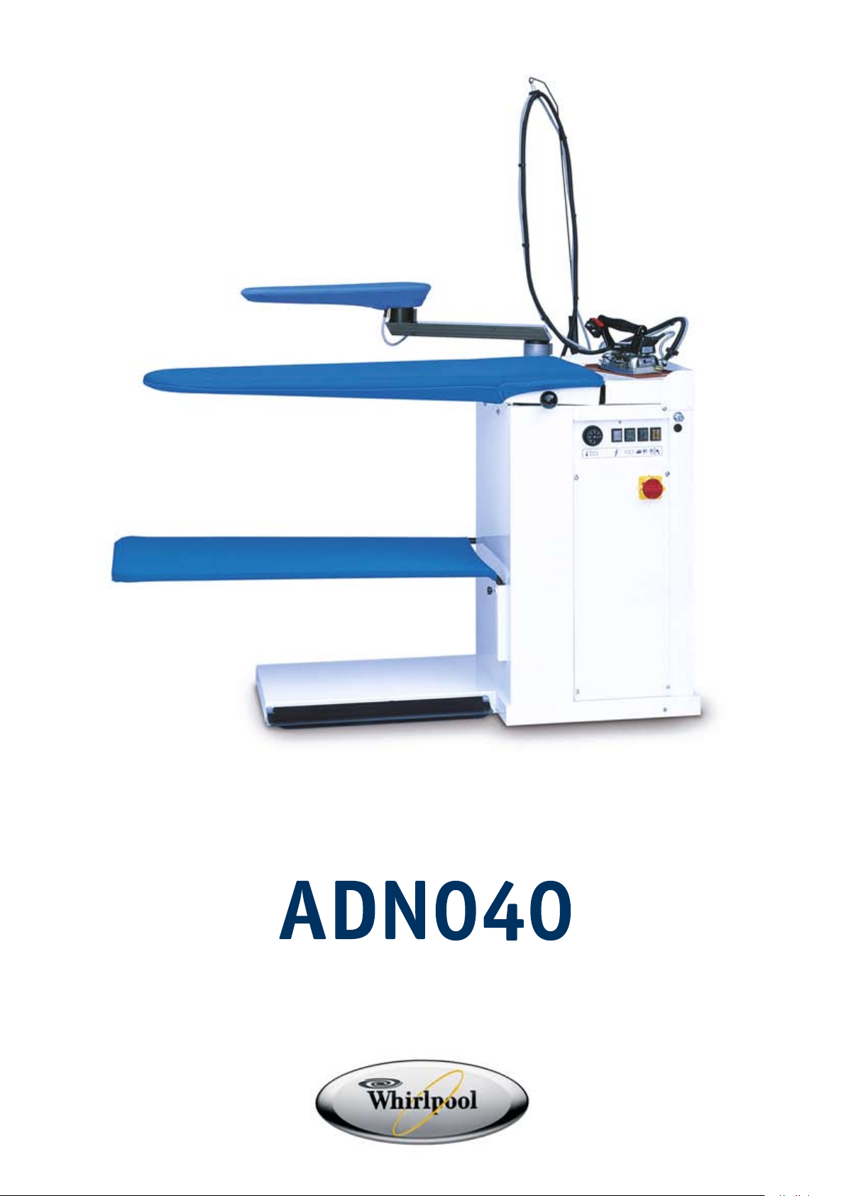
ADN040
Page 2
CONTENTS
1 INTRODUCTION
2 GENERAL DESCRIPTION
3 MACHINE IDENTIFICATION
4 TECHNICAL FEATURES
5 MACHINE COMPONENTS
6 MACHINE UNPACKING AND INSTALLATION
7 INSTRUCTIONS FOR USE
8 TROUBLESHOOTING AND SOLVING
9 PRECAUTION
10 HAZARDOUS USE
11 6 OVERALL DIMENSIONS AND DRAWINGS
12 MAINTENANCE PROCEDURES
13 DISPOSAL
14 HOW TO ORDER SPARE PARTS
15 HANDLING AND TRANSPORT
16 WARRANTY
1 INTRODUCTION
The present user’s and maintenance manual refers to the ironing table “AMBRIA”.
It is possible to receive the latest release from our Technical Commercial Department.
The present user’s and maintenance manual contains important information for the operator’s health safeguard and
safety.
This manual has to be read and kept carefully, in order to be always at the operator’s disposal in case of need.
The manufacturer cannot be held liable for any damage to things or injury to persons caused by improper use of
the machine in contrast with these instructions.
Any possible modifications effected on the components of the machine or its different use without prior written
authorization by the manufacturer, relieve the latter of injury to persons and / or damages to things, voiding any
warranty bindings, as well.
2 GENERAL DESCRIPTION
The ironing table AMBRIA is completely self-contained and doesn’t require any supporting equipment for its
operation.
This machine uses an external power supply for its operation.
The machine features a broad universal ironing board and (on request) a sleeve shape with vacuum (both of which
are padded and electrically heated), as well as a garment tray, a control panel to adjust the board temperature and
to operate the different work stations, a professional steam iron, a built-in boiler with automatic water feeding and
an automatic pressure control. Furthermore, it is possible to install on request a steam-air gun, a heated egg shape
and a stainless steel spotting shape.
The operation is very user-friendly and efficient, thanks to its control by pedal.
3 MACHINE IDENTIFICATION
A tag placed on one side of the machine indicates the type, serial number, year of construction and the voltage.
4 TECHNICAL FEATURES
Power supply 230V – 1ph / 50 Hz
230-400V – 3ph / 50 Hz
Power consumption
Boiler
Steam
3,3-3,9-4,8 Kw 0,83 Kw 0,14 Kw 1 Kw
Vacuum motor 0,6 Hp
Pump motor 0,5 Hp
Steam pressure 2,6 bar
Steam consumption
2 ÷ 10 Kg/h
Sound intensity level < 70 dB(A)
Working temperature
+ 5 ÷ + 80 °C
Working humidity 90 % max.
Storing temperature
- 20 ÷ + 50 °C
Net dimension 1550 x 550 x 950 mm.
Net weight 87 Kg
Overall dimensions (packaging included) 1520 x 580 x 1000 mm
Gross weight (packaging included) 110 Kg
WARNING:
The machine must not be supplied with different voltages than those indicated on the table.
iron
Sleeve
shape
Table
2
Page 3
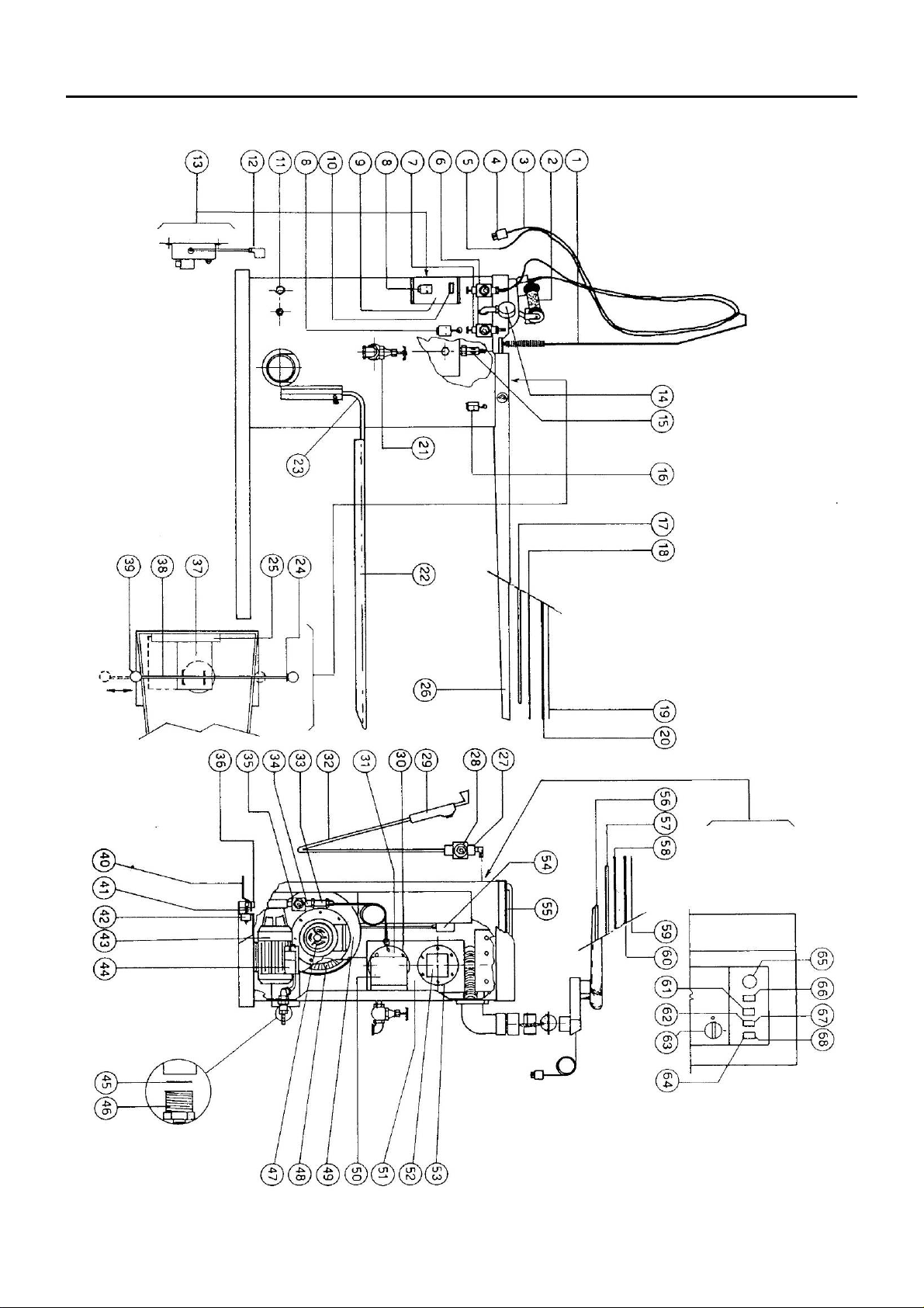
5 MACHINE COMPONENTS
The following are the main machine components:
3
Page 4
Pos. ARTICLE DESCRIPTION Pos. ARTICLE DESCRIPTION
1 534269 Antenna for cable 34 39B015 Water solenoid valve
2 Z01L10 Steam iron type U 35 39H020 Coil for water solenoid valve
3 Z23C00 Electric cable 36 184005 Pedal support
4 43H009 Iron plug by Ilme 37 173329 Plate out of stainless steel
5 07A001 Steam tube 38 184466 Rod for stainless steel plate
6 39H011 Coil for steam iron solenoid valve 39 52C003 Knob
7 39B005 Steam solenoid valve for iron 40 173320 Vacuum pedal
8 43G007 Iron socket by Ilme 41 534276 Pedal spring
9 173441 Small control case for 2nd iron fitting 42 43D002 Vacuum micro-switch
10 43A020 2nd iron switch 43 42B011 Water pump 230V / 50Hz
11 Power supply inlet 44 42G021 Pump condenser MF 10
12 301016 Connector 45 174356 Water filter
13 Z18M00 Complete fitting for second iron 46 36E006 Hose holder Ø12mm
14 35A004 Pressure gauge 47 42A002 Vacuum motor 230V / 50-60Hz
15 38S001 Safety valve 48 42H002 Vacuum fan Ø180x72
16 43G006 Socket for heated shape by Ilme 49 340017 Vacuum fan wheel box
17 213123 Table heater 1000 Watt 50 172102 Safety cover
18 161020 Perforated plate for universal table 51 202127 Boiler
19 274102
Cloth for univ. table with GB zip fastener
52 E 02 Automatic level control
20 274122 Padding and net for universal table 53 244235 Flange gasket Ø135mm
21 37B002 Gate valve for boiler exhaust 54 45G001 Pressure switch 2 ÷ 5,5 bar
22 274203 Cloth for garment tray 55 25A001 Iron rest out of silicone
23 175005 Garment tray 56 340019 Sleeve shape
24 161037 Stainless steel rail 57 213134 Sleeve shape heater 140 W
25 24A011 Or-ring 58 173323 Sleeve shape plate
26 162114 Universal table 59 E 12 Sleeve shape cloth
27 39B002 Solenoid valve for steam gun 60 E 12 Padding and net for sleeve shape
28 39H011 Coil for steam gun solenoid valve 61 43A020 Sleeve shape switch
29 Z07A00 Steam gun 62 43A014 Iron switch
30 244235 Flange gasket Ø135mm 63 43A043 Main switch
212061 Boiler heater 3,9 kW 64 43A016 Boiler warning light
31
212060 Boiler heater 3,3 kW 65 45C001 Table thermostat
212063 Boiler heater 4,8 kW 66 43A046 Voltage warning light
32 07A002 Steam tube out of silicone 67 43A014 Boiler switch
33 38W001 Check valve 68 43A016 Water warning light
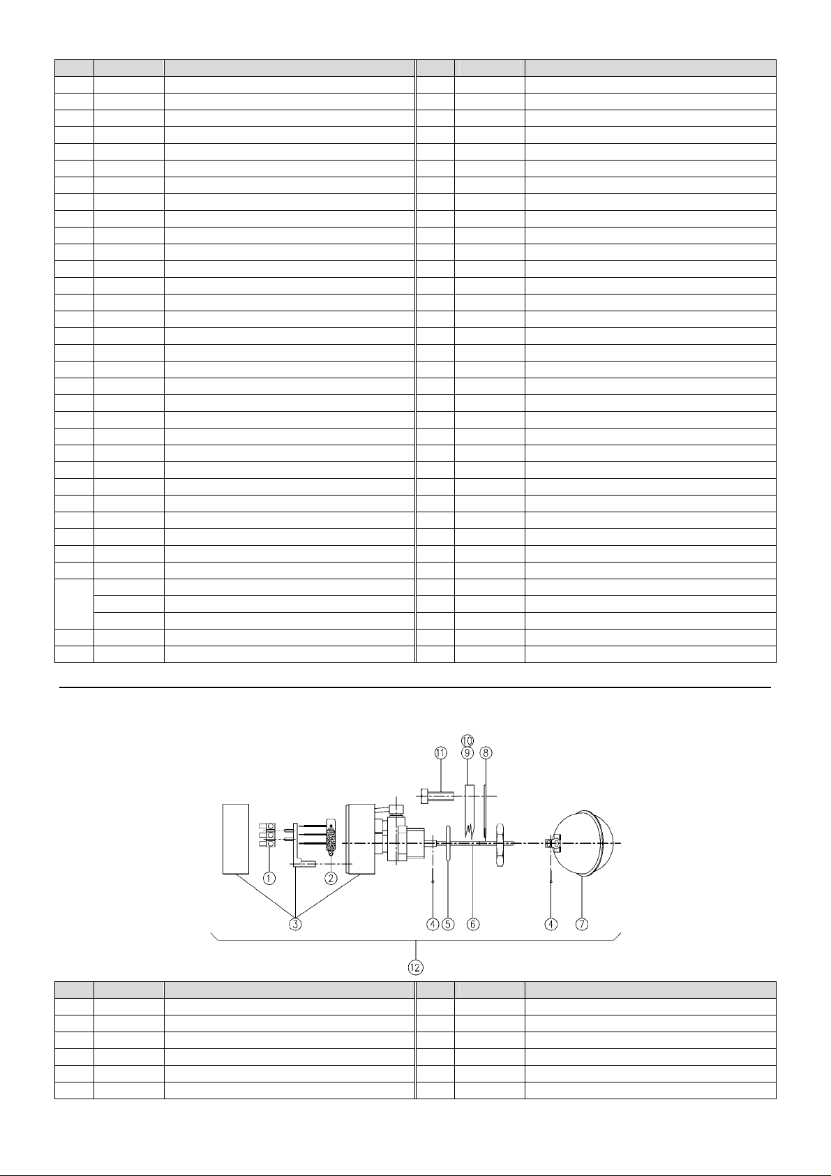
AUTOMATIC LEVEL CONTROL
Pos. ARTICLE DESCRIPTION Pos. ARTICLE DESCRIPTION
1 43J001 Clamp 7 49G001 Ball
2 49G002 Bulb 8 244236 Flange gasket
3 49G005 Complete box 9 183270 Flange Ø135
4 51P007 Split pin Ø2 x 20 10 183273 Flange Ø135 with ISPESL certification
5 24E003 Level gasket 11 50A016 Screw M10 x 30 ASTM-A193-B7
6 184318 Supporting floating rod 12 49A001 Complete automatic level
4
Page 5
IRON AND LIGHTING RAIL
Pos. ARTICLE DESCRIPTION Pos. ARTICLE DESCRIPTION
1 Z08M00 Iron support fitting 14 22K019 Push rod
2 534264 Spring 15 174520 Accessory holder
3 43A001 Balancing device 16 174521 Bracket for accessory holder
4 51X010 Ring 17 39H011 Coil for steam iron solenoid valve
5 174022 Bracket 18 39B005 Steam iron solenoid valve
6 56B002 Complete wheel 19 175108 Supporting bracket for condensation separator
7 43C009 Lamp 36W - 230V 20 46R005 Cable holder
8 43C007 Complete upper light fixture 21 244244 Gasket 30x7x3
9 174084 Front lamp support 22 43K005 Switch box
10 22A002 Bumper foot 23 43A003 Switch
173304 Track L150 24 43H001 Plug
11
173025 Track L178 25 174017 Spacer L35
12 173028 Upper column 26 174016 Spacer L43
13 202052 Condensation separator 27 173011 Bottom column
5
Page 6

LEG DIVIDER (SHORT TYPE)
Pos. ARTICLE DESCRIPTION Pos. ARTICLE DESCRIPTION
1 22K021 Cap 6 50A029 Screw M6x60
2 07A007 Isolating rubber tube 7 50J009 Washer 6x18
3 173035 Leg divider 8 50J008 Washer 8x24
4 173027 Leg divider support 9 51A003 Nut M6
5 22K025 Cap 20 x 20 10 52A004 Handwheel
HEATER FLANGE Ø130
Pos. ARTICLE DESCRIPTION Pos. ARTICLE DESCRIPTION
1 50A016 Screw M10x25 212061 Boiler heater 3,9 kW
2 244235 Gasket 212060 Boiler heater 3,3 kW
3
212063 Boiler heater 4,8 kW
6
Page 7

STEAM IRON TYPE “U”
TECHNICAL FEATURES
Power supply 220V 50 Hz
Iron heater 0,830 Kw
Working temperature
Working humidity 90 % max.
Storing temperature
Net weight 1,8 Kg
+ 5 ÷ + 80 °C
- 20 ÷ + 50 °C
Pos. ARTICLE DESCRIPTION Pos ARTICLE DESCRIPTION
4365 45A005 Thermostat with thermofuse 224 222056 Handle
720 184453 Fixing screw for body 223 184457 Fixing screw for handle
704 253297 Hand protection plate 222 514057 Fixing nut for body
520 224217 Hand wheel 221 514056 Nut for handle rod
519 173236 Micro-switch support 220 534288 Hand wheel spring
518 22K038 Cap for body screw 218 184455 Fixing screw for body
517 224217 Sheathing 216 172057 Handle support
516 304284 Micro-switch wires 209 514055 Nut for terminal board
515 43D009 Micro-switch complete of wires and sheathing 208 304282 Electrical wiring for thermostat heater
514 43K007 Micro-switch case 207 304281 E l e c t r i c a l wir i n g f o r t h e r m o s t a t t e r m i n a l board
513 184451 Micro-sw itch screw 206 304280 Ele c t r i c a l wir i n g f o r heater terminal board
510 264350 Plate 33 224255 Cable holder for plug
406 253255 Body 31 224260 Wire clamp
405/1 174020 Thermostat column 30 224215 Little spring
402 174019 Body column 29 Z23E01 Stiffened teflon shoe
401 253254 Plate with heater 18 25A002 Water spray gun
248 184449 Isolating washers 12 224210 Cable holder
247 174018 Earth spacer 11 51X005 Clip
246 22K037 Micro-switch cap 10 Z23C00 Electrical wire
245 22K036 Nut cap 9 07A002 Silicone tube
244 514058 Nut for rear cover 8 07A001 Rubber tube
242 224245 Rubber cap for wire holder 7 43H009 Plug by Ilme
230 184448 Indented washer 6 43H002 Plug by Wieland
229 222133 Rear cover 5 174009 Jointed iron hanger
228 184450 U-bolt screw 3 364297 Cable hose
227 174353 Fixing U-bolt 1 Z 23E00 Teflon shoe
225 183255 Handle rod
7
Page 8

6 MACHINE UNPACKING AND INSTALLATION
ATTENTION:
6.1 UNPACKING
Find the most suitable place where to put the machine, then remove the packaging. Make sure that the machine
has not been damaged during the transport and the storage.
The packaging material does not require any special precautions for its disposal, for it is not dangerous or polluting
at all. Please refer to the local regulations for its disposal.
6.2 MACHINE INSTALLATION
The machine has not to be anchored to the floor.
For a correct use and operation, as well as for an easy maintenance, leave enough free space around the
machine.
Do not place the machine in dangerous and/or explosive/inflammable places.
6.3 ELECTRICAL WIRING
The electrical wiring must be carried out as indicated in the drawing. Check that the supply voltage and the
frequency correspond to those indicated on the rating plate. The dimensions of the supply cable must suit the
machine absorption and comply to the current regulations. It is advisable to install a switch with fuses or a
magnetothermal one. Put the cable in the cable passage hole, then tighten. Connect the cable to the terminals of
the feeder line on the control panel, as shown on the drawing of the present manual. Check the rotation direction of
the motors; if not correct, invert two of the three input phases with each other.
ATTENTION: After having carried out all the electrical connections, make sure that the cables are protected
against any possible hits and are suitably fixed and isolated.
The unit must be installed, opened and repaired by fully qualified technicians only.
6.4 WATER CONNECTION AND BOILER EXHAUST
Connect the water pipes to the cable passage Ø12 of the machine. Install an on-off valve and a filter on the water
inlet, which has to be closed each evening, in order to avoid any water sucks into the boiler. Connect the gate valve
of the boiler exhaust (with a G 3/8” threading) to the drainage system.
7 INSTRUCTIONS FOR USE
7.1 PUTTING INTO OPERATION
• The whole unit can be used, opened and repaired by qualified technicians only.
• It is forbidden to use the machine if flooded by liquids or in particularly aggressive or explosive/inflammable
places.
• Do not ignore the dangers for the operator’s health and follow the hygienic and safety regulations.
• Check that the electrical wiring is carried out correctly according to the current regulations, and that the
fuse blocks are closed and complete of fuses.
• Make sure that the machine is intact.
7.2 USE
• Open the on-off valve of the water supply.
• Turn on the main switch of the machine.
• Press the boiler button.
• The warning light of the water supply switches on automatically (the water starts running into the boiler).
• Once the water has reached the required level the relevant warning light switches off automatically,
whereas the one of the boiler heater turns on.
• After a few minutes the boiler reaches the working pressure of 2.6 bar (check the pressure on the pressure
gauge), the relevant warning light switches off automatically.
• The generator is now ready to supply steam.
• Adjust the board temperature by means of the thermostat wheel.
• Wait until the boards reach the required temperature.
• Push the pedal to put the air suction on boards into operation.
• At the end of the work, turn off the table by means of the relevant buttons.
7.3 USE OF THE SLEEVE SHAPE
• By drawing the sleeve shape towards the ironing surface, the valve on the inside will open automatically.
Push the pedal for the vacuum operation.
7.4 USE OF THE STEAM IRON TYPE ”U”
• Turn on the iron switch.
8
Page 9

• Switch on the iron a few minutes before you start working, until the soleplate has reached the adjusted
t
t
temperature.
• In case the temperature of the soleplate has to be kept very high, we recommend to apply a Teflon
in order to prevent burns of the garment.
7.5 USE OF THE STEAM-AIR GUN
• Place the garment to be treated onto the spotting shape, making sure that it lies exactly on the vacuum
part.
• Push the vacuum pedal; by turning the condensation-jet of the gun first towards a tank until only steam
comes out.
• Draw the gun closer to the part to be treated, by pushing at the same time both the vacuum and the steam
pedal.
• Once the stain is dissolved, dry the treated part by pushing simultaneously the vacuum pedal and airbutton on the gun.
Board heater thermosta
Iron switch
Heated sleeve shape switch
Voltage warning ligh
Boiler switch
Boiler heater warning light
Water supply warning light
®
shoe
Main switch
8 TROUBLESHOOTING AND SOLVING
The following diagnostic table indicates the main irregularities, which can occur, the probable causes and their
possible solutions
In case of doubts and/or of problems, which can’t be solved, do not attempt to disassemble parts of the machine for
the troubleshooting, but contact Technical Office or seller.
DIAGNOSTIC TABLE
PROBLEMS POSSIBLE CAUSES SOLUTIONS
No suction on the boards Micro-switch of the pedal defect
The boards do not heat up Thermostat defect
The machine doesn’t turn on
Main switch not on
Switch turned off
No steam is coming out Iron or boiler switch not turned on.
The water warning light is turned
on and the water pump keeps
No water is streaming into the
boiler
on running without stopping
The heater warning light is
Leak on the boiler exhaust
always switched on and the
boiler doesn’t reach the working
Burnt heater or covered with scale
pressure
ATTENTION: if the safety valves is released, switch the boiler immediately off and contact a qualified technician.
Do not block the exhaust and do not underestimate the problem, as there could be risk of explosion.
Replace the micro-switch
Replace the thermostat
Check if the main switch is on and the
fuses.
Turn on the switch
Turn the switches on
Check if the water cock is open.
Check the presence of pressure inside the
water mains.
Check if the water filter is obstructed.
Check if the gate valve of the boiler exhaust
is well closed.
Check the heater condition.
9
Page 10

9 PRECAUTION
Read carefully the instructions and the risks related to the use of an ironing table. The operator has to know its
working functions and must clearly understand its dangers with the help of the manual.
If the machine features a steam iron, do not leave it switched on too long and place it always on the relevant iron
rest. The ironing boards and the soleplate of the iron remain hot for some minutes after their switching-off, please
pay therefore attention to the risks of burns and do not put objects on the table until its complete cooling-down.
Main electrical supply
Prior to carrying out any inspection or service on the machine, it is necessary to disconnect it from the main
electrical supply. Make sure, that nobody can reconnect it during the technical service.
Every installed electrical or electronic equipment must be earthed.
Inflammability
Adopt all the necessary precautions to avoid any direct contact of the machine with hot materials or flames. Put fire
extinguishers near the machine for an immediate intervention in event of fire.
Pressure / Steam
Before each intervention, switch off the boiler first and check that there are no residual pressures inside the boiler
or in any branch of the hydraulic circuit, as they could cause steam or product spurts, in case of disassembly of
fittings or other components.
Noise
The machine’s noise level is not very high, as it remains under 70dB (A).
10 HAZARDOUS USE
The conformity verification, according to the essential safety rules and to the provisions of the machine directive,
has already been carried out by filling out the specially provided checking lists that are included in the technical file.
The checking lists are of two kinds:
• List of dangers (drawn from EN 1050 referring to EN 292)
• Application of the main safety features (Machine Directive– appendix. 1, part 1)
The dangers described in the following have not been completely removed, but they have been deemed to
be acceptable:
• During the maintenance operation there could be some steam jets at low pressure, (maintenance operation
must therefore be carried out by using suitable protection devices)
• The user must provide for a protection against direct and indirect contacts.
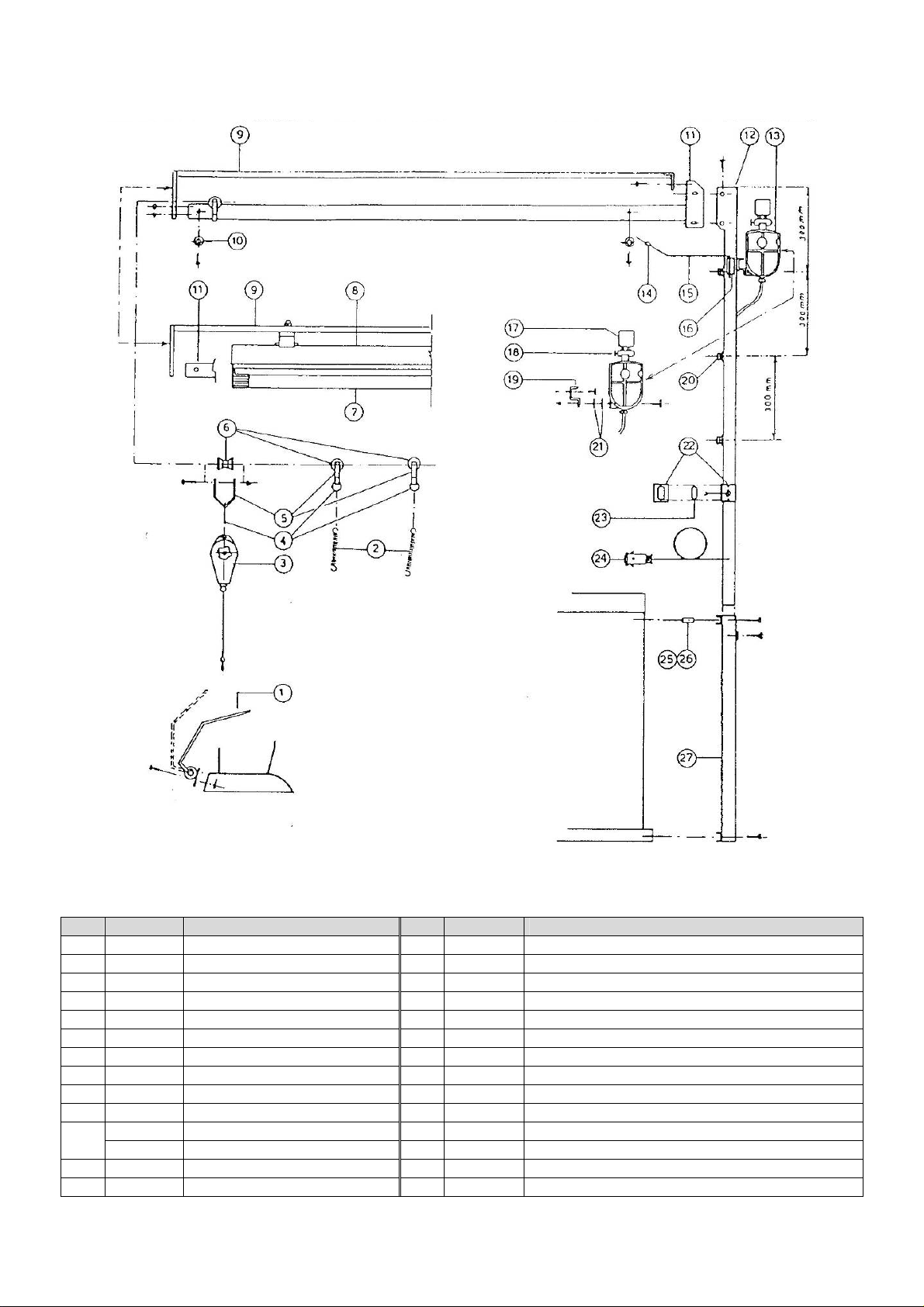
11 6 OVERALL DIMENSIONS AND DRAWINGS
1 – Steam inlet 3 – Boiler exhaust 5 – Water inlet
2 – Condensation return 4 – Power supply 6 – Vacuum exhaust
10
Page 11

11 12 13 14
Page 12

Page 13

Page 14

Page 15

15
Page 16

12 MAINTENANCE PROCEDURES
In case of irregularities or malfunctioning, please contact the service technician for the relevant checks.
Periodically, it is necessary to carry out the following operations:
OPERATION Working hours
Boiler discharge (*) 40
Cleaning of the water filter 1500
Cleaning both of boiler and heating elements 2500
Cleaning of the condensation return filter 500
(*): Discharge the boiler once it has reached 1 bar of pressure, in order to remove any limescale or dirt deposits.
When the machine is switched off, open slowly the gate valve of the boiler exhaust. We recommend to carry out
this operation before you start working and not in the evening at the end of work, as the fresh water streaming into
the boiler is rich in oxygen, increasing during the night the corrosion process inside the drum.
This machine does not require special equipment for check and/or maintenance operations. It is however advisable
to use suitable tools and personal protections in compliance with the Italian law by decree 626/94, which have to be
in good conditions (Presidential Decree 547/55), in order to avoid any damages to persons or machine
components.
Make sure that the power supply is disconnected prior to any maintenance service and that the whole
equipment is cooled down.
13 DISPOSAL
During the maintenance on the machine, or in case of its scrapping, please dispose carefully and correctly of any
polluting components, according to the local regulations. In case of scrapping, the identification rating plate and any
other document have to be destroyed.
14 HOW TO ORDER SPARE PARTS
Upon the spare parts request, please quote always:
Machine type, serial number, quantity of the requested spare parts, article number (these data can be read on the
rating plate or supplied by the technical information of the machine and by the user’s and maintenance manual).
For electrical components with a different voltage and frequency than V 230-380 50Hz (data available on the rating
plate of the faulty component), specify the right voltage and frequency after having mentioned the article number.
The technical data, the descriptions and pictures included in this manual are not binding.
The manufacturer reserves the right to make any necessary modification without notice or having to up-date the
present manual.
15 HANDLING AND TRANSPORT
Before its shipment, the machine is carefully packed in a carton box. During the shipment and storing of the
machine, pay particular attention to the upside indication on the packaging. Upon receipt, please check that the
packing is intact and store the machine in a dry place.
16 WARRANTY
All our products are supplied with a guarantee for materials and manufacturing failures for a period of maximum 12
months from the date of the delivery.
The guarantee is extended as it follows:
In case of malfunction of the machinery contact the manufacturer and quote the trouble, the model, serial number
and the operating conditions of the machine. At the receipt of the machine and after an accurate analysis, the
manufacturer reserves the right to repair or to replace the product. If the machine is still under guarantee, the
manufacturer will repair or replace it free, but if the returned product is not defective, the manufacturer reserves the
right to charge the freight to the customer (transport, etc.).
This warranty must be considered annulled in case of damages caused by an incorrect use, negligence, wear and
tear, chemical corrosion, installation in contrast with the operating instructions. Any eventual modification or
different use of the machine must be previously authorized by the manufacturer through a written document,
otherwise the manufacturer can be considered free even from the guarantee bond.
The parts of the machine which are subjected to wear and tear are not included in the guarantee. All the items not
explicitly cited or damages and expenses caused by the defects of the product itself. Implicitly the customer
accepts the conditions of the present warranty purchasing the machine. Eventual modifications to the guarantee
must be authorized by the manufacturer through a written document.
16
 Loading...