

Page 1

Installation & User’s Guide
A Note To You
Important Safety
Instructions
Electrical requirements
Receptacle wiring
Parts and Features
Installation Instructions..
Before you
Tools/supplies needed
Parts supplied for
installation
Installation tips
Window installation
Through-the-wall
installation..
Operating Instructions..
Starting your air
conditioner
Changing air direction
Cleaning Instructions
Cleaning the air filter..
Cleaning the front panel..
Maintenance Instructions..
Annual
Repairing paint damage..
Saving
Troubleshooting
Requesting Assistance
or Service
Warranty
........................
.............................
...............
.................
begin..
...........................
........................
maintenance
energy
..............................
...............................
...............
....................
.............
.......................
..........
.........
...................
...................
2
3
....... 4
5
6
....... 7
7
........ 8
8
9
9
13
....... 17
17
....... 17
18
....... 18
.. 19
. .20
20
. .22
22
23
24
28
MODELS: ACM 152XE0, ACM184XE0, ACM244XEO
PART NO. 1167492 Rev. A
AIR CONDITIONERS
Page 2
A Note to You
Thank you for buying a WHIRLPOOL@ appliance.
Because your life is getting busier and more complicated, WHIRLPOOL Air Conditioners are
easy to use, save time, and help you manage your home better. To ensure you enjoy years
of trouble-free operation, we developed this Use and Care Guide. It contains valuable
information about how to operate and maintain your appliance properly and safely. Please
read it carefully. Also, please complete and mail the Ownership Registration Card
provided with your appliance. This card helps us notify you about any new information
on your appliance.
Please record your model’s information.
Whenever you call to request service on
your appliance, you need to know your
complete model number and serial number.
You can find this information on the model
and serial number label.
Please also record the purchase date of
your appliance and your dealer’s name,
address, and telephone number.
Keep this book and the sales slip together in a safe place for future reference.
Our Consumer Assistance
Center number is toll-free
24-hours a day.
Model Number
Serial Number
Purchase Date
Dealer Name
Dealer Address
Dealer Phone
l-800-253-1301
2
Page 3

Important Safbty Instructions
Your safety is important to us.
This guide contains safety symbols and
statements. Please pay special attention to
the symbols and follow any instructions
given. Here is a brief explanation of the use
of the symbol.
This symbol alerts you to such
dangers as fire, electrical shock,
burns, cuts, and personal injury.
To reduce the risk of fire, electrical
personal injury when using your air conditioner,
follow these basic
l Read all instructions before using
your air conditioner.
*Complete the Installation Instructions
as described in this manual.
l Never allow children to operate or
play with the air conditioner.
l DO NOT operate the air conditioner
with the front panel removed.
l Disconnect power supply cord from
receptacle before servicing. Refer to
model and serial number label for
BTU capacity, amperage, voltage,
and refrigerant charge specifications.
- SAVE THESE INSTRUCTIONS -
It is your responsibility to be
sure your air conditioner:
l is installed in a window or wall that will
support the weight of the unit.
l is installed and secured according to
the Installation Instructions described
in this manual.
l is connected only to the proper kind of
outlet, with the correct electrical supply
and grounding. (See “Electrical
requirements” on page 4.)
l is the proper size for the area you want
to cool.
shock,
or
precautions:
. Never clean air conditioner parts with
flammable fluids. The fumes can create
a fire hazard or explosion.
. FOR YOUR SAFETY.
DO NOT STORE OR USE GASOLINE
OR OTHER FLAMMABLE VAPORS AND
LIQUIDS IN THE VICINITY OF THIS OR
ANY OTHER APPLIANCE. THE FUMES
CAN CREATE A FIRE HAZARD OR
EXPLOSION.
l is used only for the job it is designed to do.
l is not used by children or anyone unable
to operate it properly.
l is properly maintained.
Also, remove the Energy Label and Buy
Guide. Use a damp cloth to take off any
glue residue. Do not use sharp instruments,
flammable fluids, or abrasive cleaner. These
can damage the material.
3
Page 4
Electrical requirements
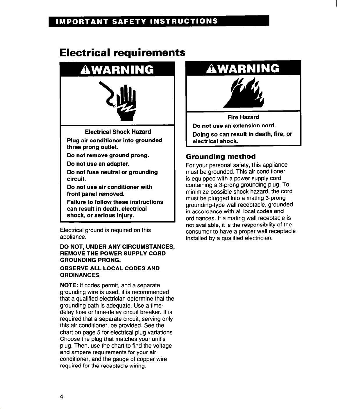
Electrical Shock Hazard
Plug air conditioner into grounded
three prong outlet.
Do not remove ground prong.
Do not use an adapter.
Do not fuse neutral or grounding
circuit.
Do not use air conditioner with
front panel removed.
Failure to follow these instructions
can result in death, electrical
shock, or serious injury.
Electrical ground is required on this
appliance.
DO NOT, UNDER ANY CIRCUMSTANCES,
REMOVE THE POWER SUPPLY CORD
GROUNDING PRONG.
OBSERVE ALL LOCAL CODES AND
ORDINANCES.
Fire Hazard
Do not use an extension cord.
Doing so can result in death, fire, or
electrical shock.
Grounding method
For your personal safety, this appliance
must be grounded. This air conditioner
is equipped with a power supply cord
containing a 3-prong grounding plug. To
minimize possible shock hazard, the cord
must be plugged into a mating 3-prong
grounding-type wall receptacle, grounded
in accordance with all local codes and
ordinances. If a mating wall receptacle is
not available, it is the responsibility of the
consumer to have a proper wall receptacle
installed by a qualified electrician.
NOTE: If codes permit, and a separate
grounding wire is used, it is recommended
that a qualified electrician determine that the
grounding path is adequate. Use a timedelay fuse or time-delay circuit breaker. It is
required that a separate circuit, serving only
this air conditioner, be provided. See the
chart on page 5 for electrical plug variations.
Choose the plug that matches your unit’s
plug. Then, use the chart to find the voltage
and ampere requirements for your air
conditioner, and the gauge of copper wire
required for the receptacle wiring.
Page 5
Receptacle wiring
See the chart below for minimum gauge for
receptacle wiring. Use copper wire only. It is
the responsibility of the consumer to provide
proper and adequate receptacle wiring,
installed by a qualified electrician. Observe
the National Electrical Code and all local
governing codes and ordinances.
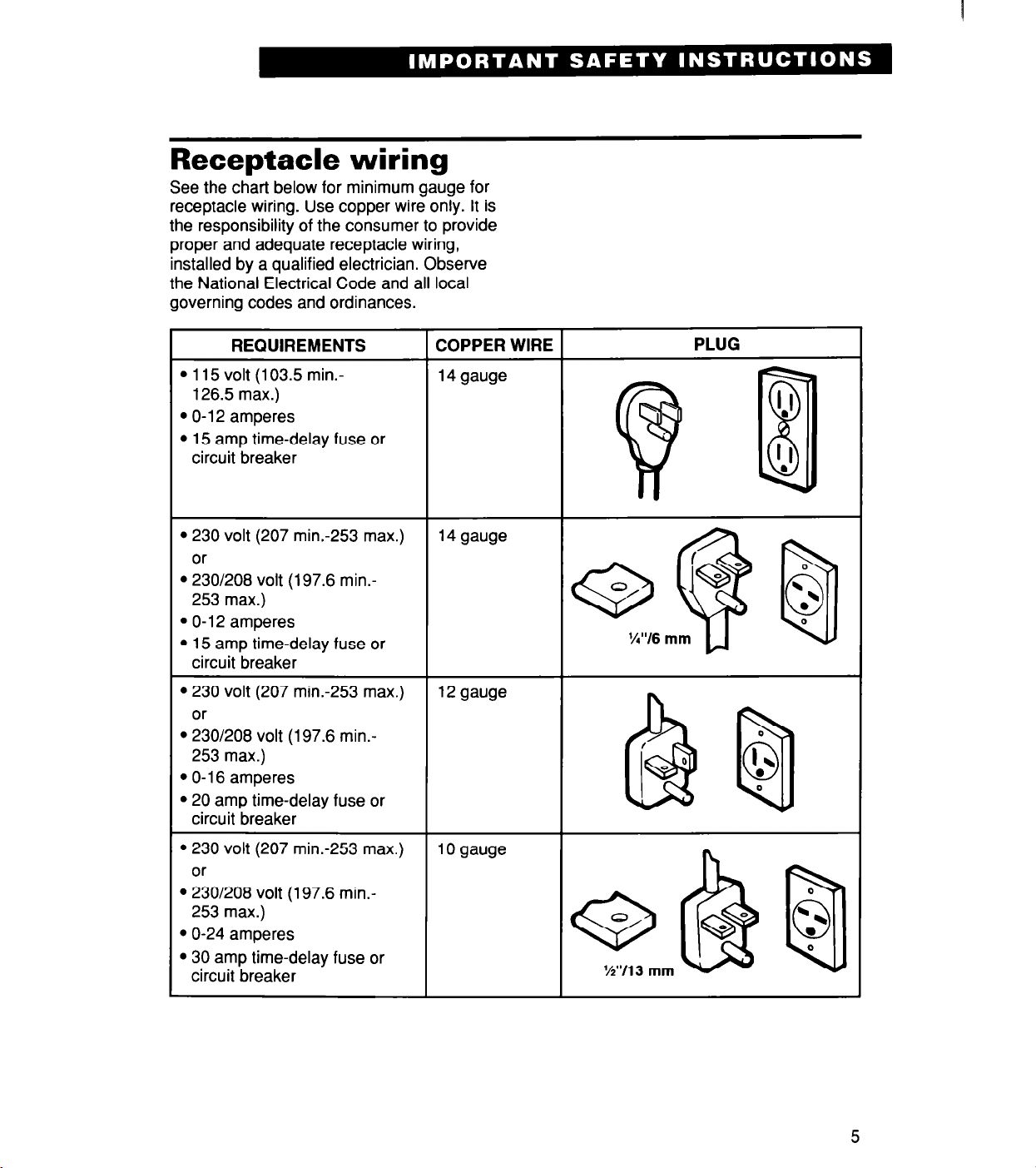
REQUIREMENTS
l 115 volt (103.5 min.-
126.5 max.)
l O-l 2 amperes
l 15 amp time-delay fuse or
circuit breaker
l 230 volt (207 min.-253 max.)
or
l 230/208 volt (197.6 min.-
253 max.)
l O-l 2 amperes
l 15 amp time-delay fuse or
circuit breaker
l 230 volt (207 min.-253 max.)
or
l 230/208 volt (197.6 min.-
253 max.)
l O-l 6 amperes
l 20 amp time-delay fuse or
circuit breaker
COPPER WIRE
14 gauge
14 gauge
12 gauge
PLUG
‘.I
!’
Bl
l 230 volt (207 min.-253 max.)
or
l 230/208 volt (197.6 min.-
253 max.)
l O-24 amperes
l 30 amp time-delay fuse or
circuit breaker
10 gauge
5
Page 6

Parts and Features
This section contains captioned illustrations of your appliance. Use them to become familiar
with where all parts and features are located and what they look like
information on
SPeCifk
parts or features quickly, page references are included.
TO
help you find
Airflow
direction
tab
(P. 17)\
Airflow louvers
(P. 17)
I
Slide-out
air filter
b 18)
I
Control panel
(P. 17)
6
/
Removable
front panel
(P. 19)
Page 7

Installation Instructions
Proper installation of your air conditioner is important for proper operation and best cooling
results. To avoid any installation problems and to ensure trouble-free performance of your
new air conditioner, please read these Installation Instructions, as well as the operating
instructions and electrical requirements before installing your unit.
IMPORTANT: Observe all governing codes and ordinances.
Excessive Weight Hazard
Use two or more people to move and
install air conditioner.
Failure
other injury.
Before you begin
Check the window/wall location where
the air conditioner will be installed for
the following:
l The opening/window is large enough.
Remember to add twice the thickness of
the wood to be used to build the frame.
l The wall/window is sturdy enough to
support the weight of the air conditioner -
145 to 200 pounds (65 to 90 kg).
l An electrical supply is within reach of the
power supply cord.
l Air will move freely into rooms to
be cooled.
to do so can result in back or
I
Window opening measurements
Wall opening measurements
7
Page 8

Tools/supplies needed
1. Flat-blade screwdriver
2. Tape measure
3. Utility knife
4. Socket wrench with
(6 mm) sockets
OR
%I” (6 mm) nut driver
5. Electric drill
6. YY (2 mm) or smaller drill bit
7. Carpenter’s level
For through-the-wall installation:
8. Wood preservative
8. #l 0 x 1” (25 mm) screws [lo]
%6”
(11 mm) and %I”
Parts supplied for installation
A. %” (10 mm) seal strips [5]
B. Side mounting brackets [2]
C. #8 x 3/B” (10 mm) hex-head sheet-metal
screws [4]
D. Filler board [l]
E. #8 x 1/2” (12.5 mm) hex-head metal
screws [4]
F. Foam seal [l]
G. Foam blocks [4]
H. #lO x %” (19 mm) round-head wood
screws [3]
I. 2%” (63.5 mm) seal strip [l]
J. Vertical supports [2]
K. Angled supports [2]
L. 3/4” (19 mm) round-head bolts [6]
M. Flat washers [6]
N. Lock washers [6]
0. Nuts [6]
P. Wall rail [l]
Q. Foam window rail seal [l]
R. Window lock bracket [l]
S. Plastic drain cup [l]
T. Gum-type sealer [l]
Installation parts are supplied for double-
hung windows up to 40” (1 ,016 mm) wide.
Installation up to 54” (1,372 mm) can be
made with a special “Wide-window kit” from
your dealer or authorized service center.
Page 9

Installation tips
l Handle the air conditioner with care. Watch
out for the sharp metal fins on the front
and rear coils.
l Be sure your air conditioner does not fall
out of the opening during installation.
Window installation
1. Remove the ground wire and screw from
the front of the unit base. Save grounding
screw for reattachment in Step 23.
2. Attach 3/g” (10 mm) seal strip (A) to
bottom of both side mounting brackets
(sides with screw holes). Cut strips to
length and save extra for use later.
3. Attach side mounting brackets (B) to
cabinet. Place side mounting brackets on
cabinet so bent edge is toward front of
cabinet. Attach each with 2 hex-head
metal screws (C).
4. Slide unit out of cabinet. Grasp handle
and slide unit straight out of cabinet. Place
unit on cardboard to protect your floor.
5. Place empty cabinet in window. Lower
window sash to hold cabinet in place.
Make sure the cabinet is centered in the
window opening.
6. Measure width of window channel and
subtract thickness of filler board. Cut
foam blocks 1/4” (6 mm) wider than this
measurement. The blocks will be used
later in Step 15.
l Do not install the air conditioner in an area
where the front panel will be exposed to
heat sources that will raise the panel
surface temperature above 120°F (50°C).
7. Determine proper size for filler board
(D). Measure the distance from the right
edge of the cabinet to the inside of the
right window channel. Then add KY”
(3 mm) to that measurement. Repeat for
left side.
I
I
H
continued on next page
9
Page 10

8. Cut filler board (D) to size with utility
knife. Cut in from the outside edges.
The outside edges should have screw
holes in them.
9. Apply %” (10 mm) seal strip (left over
from Step 2) to the filler boards. Apply
seal strips to the bottom front and
outside front edges of the filler boards.
10. Attach left filler board to cabinet.
Pull cabinet part way out of the window.
Then attach the left filler board to the
front of the left side mounting bracket.
Use W’ (12.5 mm) hex-head metal
screws (E).
11. Position left filler board in window
channel. Place cabinet back into
window. Make sure left filler board sits
tightly against the window channel.
12. Attach right filler board to cabinet.
Insert right filler board into right window
channel. Push filler board against right
side mounting bracket and attach it with
W’ (12.5 mm) hex-head metal screws (E).
13. Apply foam seal (F). Measure from
right inside edge of window frame to left
inside edge. Then cut the foam seal,
with square ends, to fit. Hold the cabinet
to prevent it from falling. Raise window
sash and place adhesive side of foam
seal along underside of window.
14. Make sure filler boards are as far forward (toward inside room) in window
channels as possible.
15. insert foam blocks (G) into window
channels - behind filler boards about 34 inches from the top and bottom edges.
The blocks keep the filler board tight to
the window channel.
10
Page 11

16. Fasten cabinet to window sill. Lower
window sash firmly onto cabinet. Place a
carpenter’s level inside the cabinet and
make sure cabinet is level side-to-side.
Then drill starter holes into the cabinet
base and the window sill. Use roundhead wood screws (H) to fasten cabinet
to window sill, but do not tighten the
screws.
17. Make sure cabinet has proper out-
ward slope. Place carpenter’s level in
the right side of the cabinet. There
should be a l/2 bubble tilt (W [6 mm]per
foot [30.5 cm]) toward the outside.
Repeat for left side of cabinet. The tilt
to the outside is needed for proper
drainage.
18. Attach 2%” (63.5 mm) seal strip (I) to
inside of cabinet. Make sure the seal
strip is flush with the front edge of the
cabinet. This seal strip provides a seal
between the air conditioner base and
the cabinet.
19. Assemble the outside support. Attach
the vertical supports (J) to the angled
supports (K). Use the round-head bolts
(L), flat washers (M), lock washers (N)
and the nuts (0) for attachments. Then
attach these supports to the bottom of
the cabinet, but DO NOT tighten the
bolts at this time.
Attach the wall rail (P) to the bottom
of the supports and slide the support
assembly toward the house until the wall
rail presses firmly against the wall.
Check that you have the % bubble tilt
to the outside. This is needed for proper
drainage.
Now tighten all bolts. Tighten angled
support bolts last so wall rail fits tightly
against the house.
NOTE: If your house is constructed of
materials that could be damaged by the
wall rail, fasten a board or other protective material to the wall rail so that it is
between the wall rail and the house.
continued on next page
11
Page 12

20. install foam window rail seal (Q), the
window lock bracket (R), and the
plastic drain cup (S).
l Insert foam rail seal between the top of
the lower window sash and the glass of
the upper window.
l Place window lock bracket on top of
lower window sash and against upper
window sash. Drill a starter hole
through the lock bracket into the
window sash. Attach window lock
bracket.
l Insert plastic drain cup into hole in right
side of cabinet base.
NOTE: Install window lock bracket to
prevent air conditioner from falling out of
the window.
21. Seal any small openings around
window with gum-type sealer (T).
22. insert air conditioner into cabinet.
Electrical Shock Hazard
Connect green ground wire to
cabinet.
Failure to do so can result in death
or electrical shock.
23. Reattach ground wire with grounding
screw. Put excess grounded wire
between the coils and the cabinet.
12
Page 13

24. Attach the front panel. Remove the 2
front panel screws from unit base.
Replace front panel by pushing it straight
on and then lowering it slightly to lock it
in place. Attach bottom front of panel by
reinserting the 2 front panel screws.
Through-the-wall installation
It is the consumer’s responsibility and
obligation to have this product installed
by a qualified technician who is familiar
with through-the-wall room air conditioner
installations.
1. Cut an opening through the wail. Remove any insulation and keep for Step 8.
2. Measure depth of wail opening and
construct finish frame. Use 1” (25 mm)
or heavier lumber for wood frame construction. When using a wood, metal, or
plastic molding, the finish frame should
line up with the inside wall. If a plastered
wall is to be flush with the cabinet, and no
molding is used, the finish frame must be
set %” (13 mm) back from the finished
plaster surface. See illustrations at right
for frame construction and brick veneer
construction information.
Finish frame measurements include:
A - Wall opening width
B - Wall opening height
C - Depends on wall thickness and
type of molding
NOTE: Apply wood preservative to the
surface exposed to the outside.
continued on next page
13
Page 14

3. insert finish frame into wail opening.
Square and level the frame. Nail frame
securely to the wall studs.
4. Remove the ground wire and screw
from the front of the unit base. Save
grounding screw for reattachment in
Step 13.
5. Slide unit out of cabinet. Grasp handle
and slide unit straight out of cabinet.
Place unit on cardboard to protect your
floor covering.
6. insert cabinet into the wail opening.
The top of the cabinet should extend W
(13 mm) into the room. If there is trim, the
cabinet should extend W’ (13 mm) past
the trim.
7. Check the outward slope of the cabinet. Place a carpenter’s level inside the
cabinet on the right side. There should be
l/2 bubble (%” [6 mm] per foot [30.5 cm])
slope toward the outside. Also check the
left side.
NOTE: Make sure the air conditioner
cabinet has the proper outward slope so
condensate water runs to the outside or
damage could result to the floor or wall.
8. Seal opening between cabinet and
finish frame. Use the insulation removed
in Step 1.
9. Attach cabinet to finish frame. Use #lO
x 1” (25 mm) wood screws (not supplied)
to attach cabinet to the frame.
IMPORTANT: Do not over-tighten screws
or the cabinet will distort and provide a
poor air seal between the cabinet and the
air conditioner.
14
Page 15

10. Place the 2%” (63.5 mm) seal strip (I)
inside the cabinet. Make sure the seal
is flush with the cabinet front edge.
NOTE: This seal strip fits between the
air conditioner base and the cabinet.
11. insert drain cup (S). Place drain cup
through hole in cabinet rail.
12. insert air conditioner into cabinet.
Electrical Shock Hazard
Connect green ground wire to
cabinet.
Failure to do so can result in death
or electrical shock.
lii!iJ
. . : .*-, *. . . .
:‘:,. .::*.. c .
. . . . . . > . ..-.
hII*
. . - . . * ;. . :::.. .
. *.>‘. -.
‘.
i
.,; i ::. * .
.
. .
13. Reattach ground wire with grounding
screw. Put excess grounded wire
between the coils and the cabinet.
continued on next page
15
Page 16

14. Attach the front panel. Remove the
2 front panel screws from unit base.
Replace front panel by pushing it
straight on and then lowering it slightly
to lock it in place. Attach bottom front of
panel by reinserting the 2 front
panel screws.
15. Caulk ail outside wail openings
around the installation and cabinet.
16. install decorative molding. If desired,
install molding around room side of
cabinet.
16
Page 17

Operating Instructions
Starting your air conditioner
1.
Plug air conditioner into a grounded
3-prong outlet.
2.
Set Fan Control to desired setting.
(All settings below not on all models.)
HIGH COOL . . . . . . . . . . . . for maximum cooling
MEDIUM COOL
LOW COOL
FAN ONLY . . . . . . . . . . . . . . . . . . . .
3. Set Thermostat to a mid-setting. You can
adjust the air conditioner’s performance
by resetting the Thermostat to a higher
or lower setting. You will need to experi-
ment to find the setting(s) which work
best for you.
NOTE: If you turn your air conditioner off or
if the compressor turns off when you lower
the Thermostat, wait at least 3 minutes
before turning unit back on. Failure to do so
could blow a household fuse or trip a circuit
breaker.
. . . . . . . . . . . for normal
. . . . . . . . . . . . . . for sleeping
for
circulating air
without cooling
cooling
comfort
Changing air direction
The louvers in the top section of the air
conditioner front panel control the direction
of the cooled air. Move the tab in the direction you want the air to go - up, down, or
straight ahead.
17
Page 18

Cleaning Instructions
Proper use and care of your air conditioner will help ensure longer life of the unit and lower
operating costs. Follow these cleaning instructions.
Cleaning the air filter
The air filter is cleanable. A clean filter helps
remove dust, lint, and other particles from
the air. Check every 2 weeks to see if the
filter needs to be cleaned.
Remove air filter from front panel.
1.
l Grasp filter handle.
l Slide filter straight up and out of the
front panel.
Clean filter using a vacuum cleaner.
2.
OR
If very dirty, wash filter with warm water
and a mild detergent. Air dry thoroughly
before replacing.
3.
Replace air filter.
l Guide bottom of filter into filter slot in
front panel.
l Slide filter straight down into front panel.
NOTE: The front panel does not have to be
removed to clean the filter.
18
Page 19

Cleaning the front panel
Explosion Hazard
Unplug power cord from outlet
before cleaning air conditioner.
Use only nonflammable cleaners.
Failure to follow these instructions
can result in death, explosion, fire,
or electrical shock.
1. Unplug the power cord.
2. Remove the front panel from the unit.
l Remove the 2 screws from the bottom
edge of the front panel.
l Lift front panel slightly and then pull it
toward you.
3. Remove the slide-out air filter from the
front panel. Clean it separately. See
“Cleaning the air filter.”
4. Clean front panel with warm water and a
mild soap or detergent. Use a soft cloth.
Rinse and dry.
5. Wipe the control panel clean with a soft,
dry cloth.
6. Replace the front panel.
l Push it straight onto the cabinet. Then
lower it slightly to lock it in place.
l Replace the 2 screws in the base of the
front panel.
7. Plug in the power cord.
19
Page 20

Maintenance Instructions
Annual maintenance
Your air conditioner needs annual mainte-
nance to ensure steady, top performance
throughout the year.
Call the service company recommended
by your dealer to:
l Inspect and clean the coils and conden-
sate water passages.
l Check fan and fan motor.
The compressor and fan motor are sealed
and need no oiling. Expense of the annual
inspection is the consumer’s responsibility.
NOTE: If you are familiar with electrical
appliances, you can do the cleaning and
maintenance yourself. If you choose to do
so, follow these steps:
Electrical Shock Hazard
Unplug power cord from outlet
before servicing.
Be sure no liquid gets into the
motor, electrical control box, or
compressor terminals.
Failure to follow these instructions
can result in death, electrical
shock, or serious injury.
Excessive Weight Hazard
Use two or more people to move and
install air conditioner.
Failure to do so can result in back or
other injury.
20
Page 21

NOTE: Do not lift, push, or pull on any white
beaded foam (expanded polystyrene) parts.
1.
Unplug power cord.
2.
Remove the front panel from the unit.
. Remove the 2 screws at the base of
the front panel.
. Lift front panel slightly and then pull it
toward you.
3.
Slide unit out of cabinet using the wire
handle. Watch out for the sharp metal fins
on the front and rear coils.
NOTE: Water may have collected inside
the air conditioner cabinet, and it could
spill on the floor. Handle unit carefully.
4.
Wrap the motor, connector plug, electrical
control box, and compressor terminal box
in plastic film. Make sure no liquid gets
inside any of these parts. It could damage
the insulation and cause serious
mechanical problems.
NOTE: Water from rainfall or normal
operation does not harm these
components.
5.
Carefully clean and hose out the base,
condenser coils, and condensate pans.
Clean at least once a year, or more often
if the condenser coil and pan collect dirt,
sand, leaves, insects, or algae. Also
clean if you detect an odor coming from
the air conditioner.
6.
Remove the plastic film from the motor
and electrical parts.
7.
Replace air conditioner in the cabinet.
8.
Replace the front panel.
l Push front panel straight onto cabinet.
Then lower it slightly to lock it in place.
l Replace the 2 screws in the base of the
front panel.
9.
Plug in power cord.
NOTE: It is a good idea to wait 24 hours
before starting the unit again. This allows
time for all areas to dry thoroughly.
21
Page 22

Repairing paint damage
Check once or twice a year. This is very
important, especially in areas near oceans
or where rust is a problem. If needed, touch
up with a good grade enamel paint.
Saving energy
You can help save energy by doing the
following.
l Improve your home’s insulation. Seal
doors and windows. Close fireplace flues.
l Close blinds or drapes on the sunny side
of the house. Add awnings.
l Check air filter often to make sure it
is clean.
l Do not block airflow with drapes or
furniture.
l Ventilate your attic. High temperatures in
the attic add to the cooling load of your air
conditioner.
l Try not to use heat-producing appliances
during the hottest part of the day.
l Turn lights and appliances off when they
are not needed.
l Keep heat registers and cool-air
returns closed.
l Use exhaust/venting fans while cooling,
bathing, and doing laundry.
l Turn your Fan Control to Off if you will be
away for a long time. The air conditioner
will not come on again until the Fan
Control is set to a Cool setting.
22
Page 23

Troubleshooting
Before calling for service:
Performance problems often result from little things you can fix yourself without tools
of any kind.
PROBLEM
Unit won’t run
SOLUTION
l Make sure the power cord is plugged into a live circuit
with the proper voltage.
l Replace household fuse or reset the circuit breaker.
l Make sure the Fan Control is not set to Off.
l In case of local power failure, wait for power to be
restored.
Unit blows household fuses
or trips circuit breaker
l Replace household fuse with a time-delay fuse of the
correct capacity.
l Do not use an extension cord with this or any other
appliance.
l Wait at least 3 minutes after turning unit off to turn it
on again.
Unit turns off and on OR unit
does not cool room
l Clean the filter.
l Clean the coils.
l Use exhaust/venting fans to reduce room heat.
l Set Fan Control to a higher fan speed.
l Set Thermostat to a higher setting.
Normal operating sounds
When your air conditioner is operating
normally, you will hear such sounds as:
l Droplets of water hitting the condenser,
causing a “pinging” or “clicking” sound.
Water droplets help cool the condenser.
l Air movement from the fan - especially on
High fan speed settings.
l Clicks from the cooling cycle.
Sounds also may be caused by house
construction - such as vibration of the unit
due to wall construction or unsteady window
mounting area.
23
Page 24

Requesting Assistance or Service
For service in the U.S.:
1. If you need assistance* . . .
Call our toll-free Consumer Assistance
Center telephone number from anywhere in
the U.S.A.:
l-800-253-1 301
and talk to one of our trained consultants.
The consultant can instruct you in how to
obtain satisfactory operation from your
appliance or, if service is necessary, recom-
mend a qualified service company in
your area.
2. If you need service* . . .
We have a nationwide network of authorized
service companies. Our service technicians
are trained to fulfill the product warranty and
provide after-warranty service, anywhere in
the United States. To locate an authorized
Whirlpool service company in your area, call
our Consumer Assistance Center telephone
number (see Step 1) or look in your telephone directory Yellow Pages under:
APPLIANCES - HOUSEHOLD -
MAJOR -SERVICE & REPAIR
4. If you are not satisfied with
how the problem was
solved* . . .
l Contact the Major Appliance Consumer
Action Program (MACAP). MACAP is a
group of independent consumer experts
that voices consumer views at the highest
levels of the major appliance industry.
l Contact MACAP only when the dealer and
authorized service company have failed to
resolve your problem.
Major Appliance Consumer Action
Program
20 North Wacker Drive
Chicago, IL 60606
l MACAP will, in turn, inform us of
your action.
l When requesting assistance or service,
please provide: model number, serial
number, date of purchase, and a complete
description of the problem. This information will help us respond to your request
properly.
3. If you need FSP@ replacement parts’ . . .
To locate replacement parts in your area,
refer to Step 2 above or call our Consumer
Assistance Center telephone number
in Step 1.
24
Page 25

25
Page 26

26
Page 27

27
Page 28

WHIRLPOOL@ Warranty
LENGTH OF WARRANTY
FULL ONE-YEAR WARRANTY
FROM DATE OF PURCHASE FULL FIVE-YEAR WARRANTY
FROM DATE OF PURCHASE
WE WILL PAY FOR
FSP@ replacement parts and repair labor to
correct defects in materials or workmanship.
FSP replacement parts and repair labor to correct
defects in materials or workmanship in the sealed
refrigeration system. These parts are:
1. Compressor
2. Evaporator
3. Condenser
4. Drier-Strainer
5. Connecting Tubing
WE WILL NOT PAY FOR
A. Service calls to:
1. Correct the installation of your air conditioner.
2. Instruct you how to use your air conditioner.
3. Replace house fuses or correct house wiring.
4. Clean or replace the air filter.
B. Pickup and delivery. Your air conditioner is designed to be repaired in the home.
C. Damage to your air conditioner caused by accident, misuse, fire, flood, acts of God, or
use of products not approved by Whirlpool.
D. The removal and reinstallation of your air conditioner if it is installed in an overhead or
other inaccessible location or is not installed in accordance with published installation
instructions.
E. Repairs to parts or systems caused by unauthorized modifications made to the
appliance.
f
El94
Service under the full warranties must be provided by an authorized service company.
WHIRLPOOL CORPORATION SHALL NOT BE LIABLE FOR INCIDENTAL OR
CONSEQUENTIAL DAMAGES. Some states do not allow the exclusion or limitation of
incidental or consequential damages so this exclusion or limitation may not apply to you. This
warranty gives you specific legal rights, and you may also have other rights which vary from
state to state.
Outside the United States, a different warranty may apply. For details, please contact
your authorized Whirlpool dealer.
If you need service, first see the “Troubleshooting” section of this book. After checking
“Troubleshooting,” additional help can be found by checking the “Requesting Assistance or
Service” section or by calling our Consumer Assistance Center telephone number,
l-800-253-1301, from anywhere in the U.S.A.
PART NO. 1187492 Rev. A
0 1996 Whirlpool Corparal~on
o Regislered Trademark of Whirlpool, U S.A.
Prmied in the U.S.A.
2l96
 Loading...