

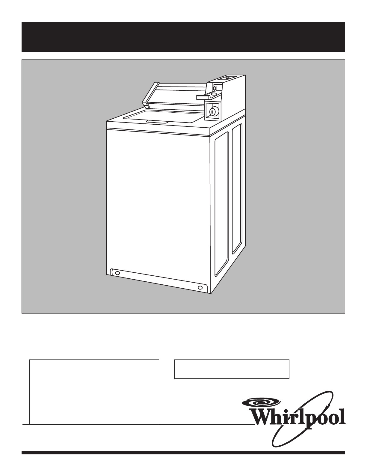
Whirlpool 8315965 User Manual
Installation Instructions
IMPORTANT:
Read and save
these instructions
IMPORTANT:
Installer: Leave Installation Instructions
with the owner.
Owner: Keep Installation Instructions for
future reference.
Save Installation Instructions for local
electrical inspector’s use.
COMMERCIAL
ELECTRONIC WASHER
120-volt, 60-Hz Models
Part No. 8315965
COMMERCIAL
LAUNDRY
PRODUCTS
®
www.whirlpool.com
Check location where washer will be
installed. Proper installation is your
responsibility. Make sure you have
everything necessary for correct
installation.
Do Not store or operate washer below
32°F (0°C) (some water may remain in
washer).
Hot and cold water faucets: Must be
within 4 feet (1.2 meters) of the back
of the washer and provide water
pressure 10 - 100 PSI (69-690 kPa). A
pressure reduction valve should be
used in the supply line where inlet
pressure entering the building
exceeds 100 PSI (690 kPa) to prevent
damage to the washer mixing valve.
Grounded
electrical outlet
is required. See
Electrical
requirements.
Single washer
installations require
12-inch (30 cm)
minimum risers to
provide an air
cushion and
prevent noise and
damage to valves.
Untape and
open washer
lid. Remove
packages and
hoses from
washer.
Water heater: Set to
deliver 140°F to 160°F
(60°C-70°C) water to
the washer.
Standpipe drain system: Needs a twoinch (5 cm) minimum carry-away
capacity of 17 gallons (64.4 liters) per
minute. Top of standpipe must be at
least 39 inches (99 cm) high and no
higher than 72 inches (183 cm) from
bottom of washer.
Level floor: Maximum slope
under washer — 1 inch (2.5 cm).
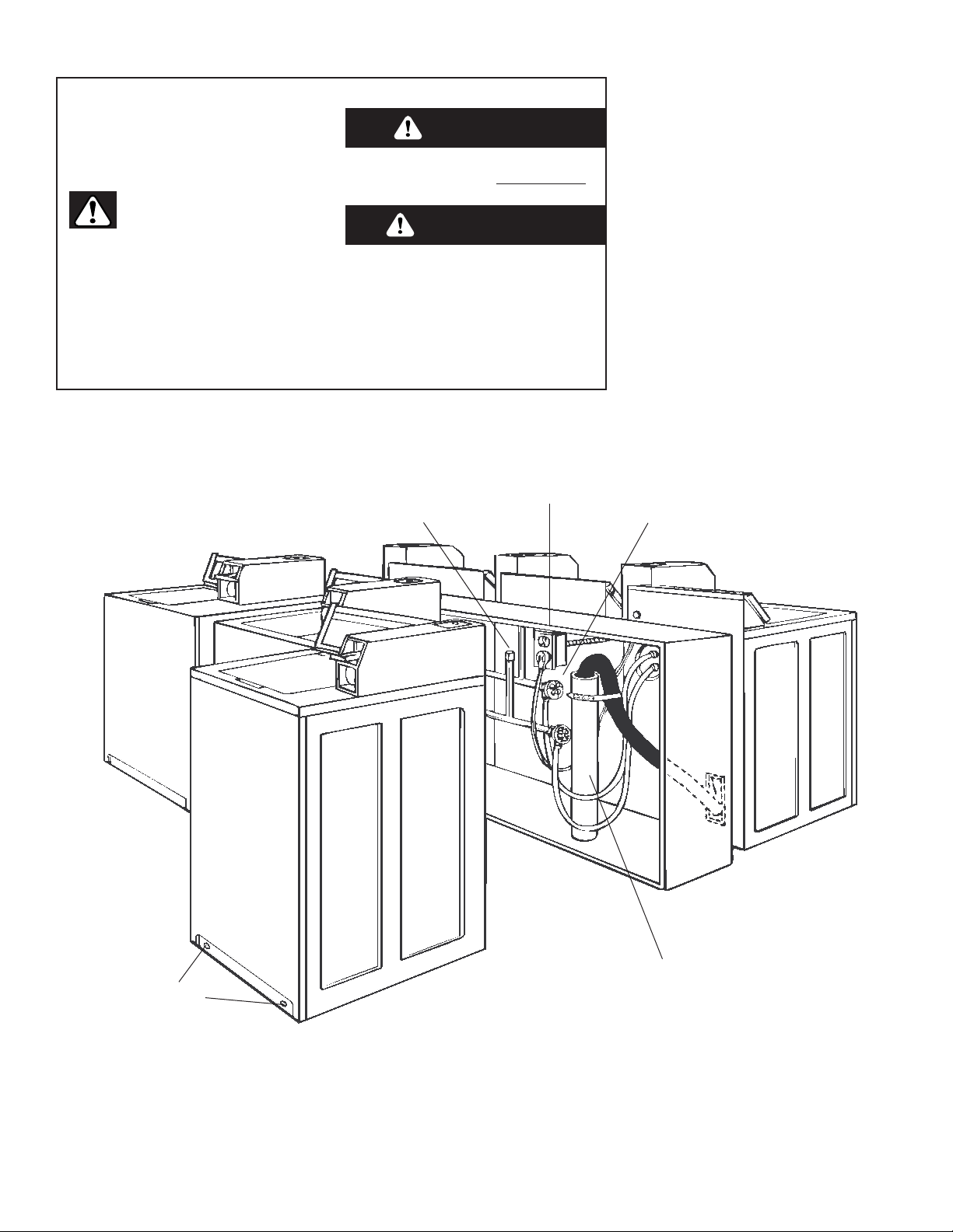
Front access to the pump area is
available by removing 2 No. T20
Torx screws and then removing the
front panel.
Support: Floor must be sturdy
enough to support loaded washer
weight of 315 pounds (143 Kg).
A floor drain should be
provided under the bulkhead.
Prefabricated bulkheads with
electrical outlets, water supply
lines and drain facilities should
be used only where local
codes permit.
Important: Observe all governing
codes and ordinances.
PAGE 2
Before you start...
We have provided many important
safety message in this manual and
on your appliance. Always read
and obey all safety messages.
WARNING
This is the safety alert symbol.
This symbol alerts you to
potential hazards that can kill or
hurt you and others.
All safety messages will be preceded
by the safety alert symbol and the
word “DANGER” or “WARNING”.
These words mean:
All safety messages will tell you
what the potential hazard is, tell you
how to reduce the chance of injury,
and tell you what can happen if the
instructions are not followed.
You can be killed or seriously
injured if you don’t immediately
follow instructions.
You can be killed or seriously
injured if you don’t follow
instructions.
D ANGER
Your safety and the safety of others are very important.
No. T20 TORX
®
screws
® Registered trademark of TEXTRON
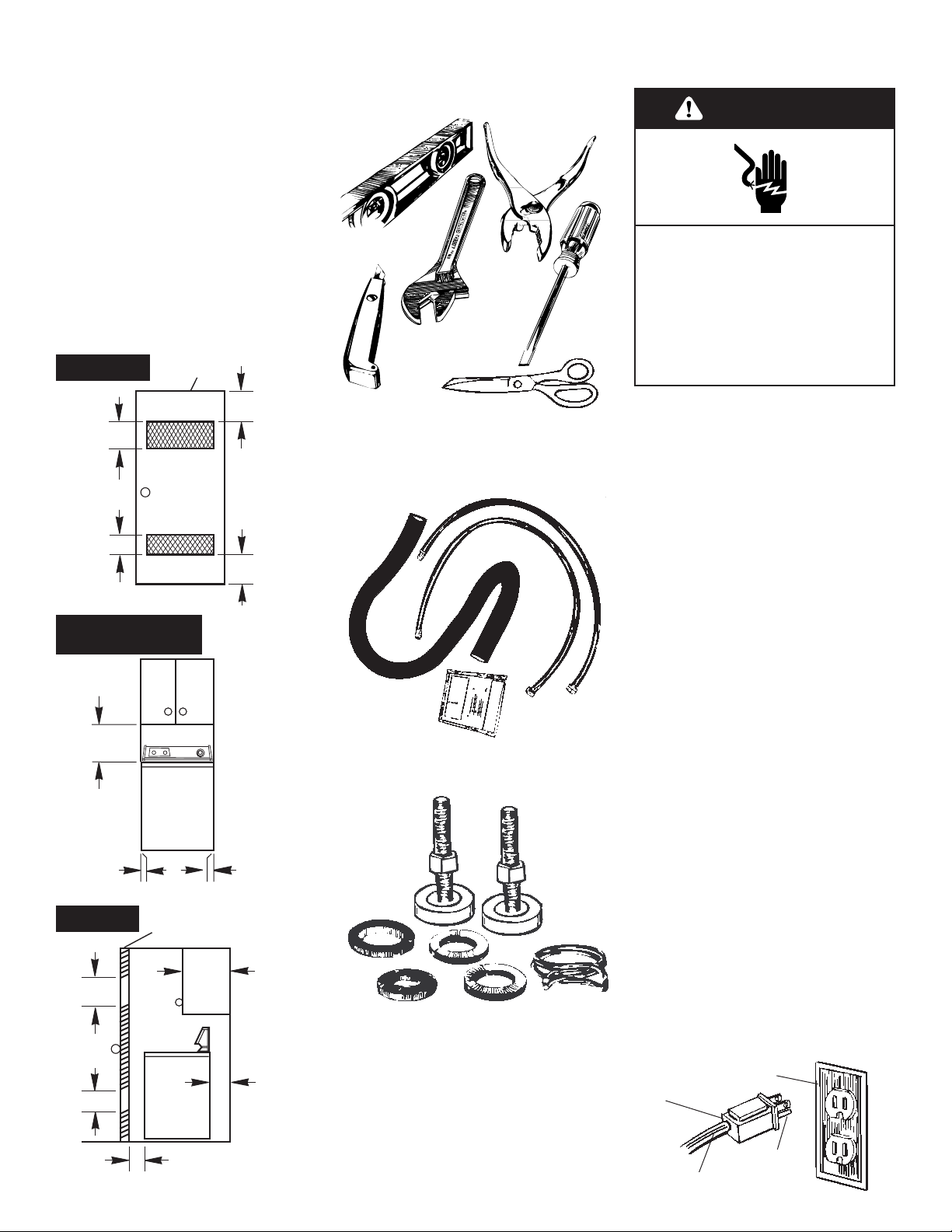
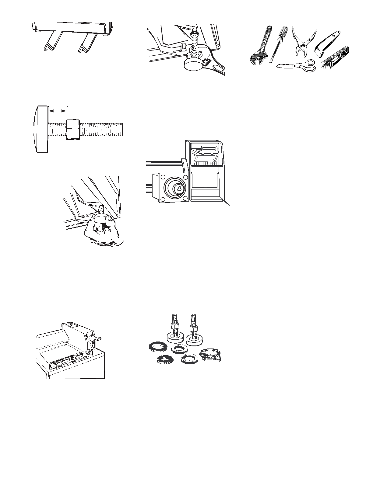
Tools needed for
installation:
level
pliers
utility
knife
wrench
scissors
flat-blade
screwdriver
Electrical requirements
ground
prong
Figure 1
PAGE 3
3-prong groundtype outlet
3-prong
ground
plug
power
supply cord
Plug into a grounded 3-prong outlet.
Do not remove ground prong.
Do not use an adapter.
Do not use an extension cord.
Failure to follow these instructions
can result in death, fire, or electrical
shock.
Electrical Shock Hazard
Parts supplied for
installation:
s
Remove parts from packages. Check
that all parts were included.
1 hose clamp
2 inlet hoses
4 flat water hose washers
2 front-leveling legs with nuts
1 drain hose
Recommended
ground method
For your personal safety, this appliance
must be grounded. This appliance is
equipped with a power supply cord
having 3-prong ground plug. To minimize
possible shock hazard, the cord must be
plugged into a mating 3-prong groundtype outlet, grounded in accordance with
local codes and ordinances. See Figure 1.
If a mating outlet is not available, it is the
personal responsibility and obligation of
the customer to have a properly grounded
3-prong outlet installed by a qualified
electrician.
WARNING – Improper connection of the
equipment-grounding conductor can
result in a risk of electric shock. Check with
a qualified electrician or serviceman if you
are in doubt as to whether the appliance is
properly grounded. Do not modify the plug
provided with the appliance – if it will not fit
the outlet, have a proper outlet installed by
a qualified electrician.
WARNING
*0"
*0"
Front view
(door not shown)
Side view
Minimum installation spacing
Recessed area instructions
This washer may be installed in a
recessed area or closet.
The installation dimensions shown are
the minimum spaces allowable.
Additional spacing should be
considered for ease of installation
and servicing. If closet door is
installed, the minimum air openings in
top and bottom of door are required.
Louvered doors with air openings in
top and bottom are acceptable.
Companion appliance spacing
should be considered.
closet door
Front view
closet door
17"
(43 cm)
14"
(35 cm)
max.
4"
(10 cm)
min.
1" (2.5 cm)
min.
3"
(7.6 cm)
3"
(7.6 cm)
24 sq. in.
(155 sq. cm)
48 sq. in.
(310 sq. cm)
24 sq. in.
(155 sq. cm)
48 sq. in.
(310 sq. cm)
If codes permit and a separate ground wire
is used, it is recommended that a qualified
electrician determine that the ground path
is adequate.
Do Not ground to a gas pipe.
Check with a qualified electrician if you are
not sure the washer is properly grounded.
Do Not have a fuse in the neutral or ground
circuit.
A 120-volt, 60-Hz, AC-only, 15- or
20-ampere fused electrical supply is
required. (Time-delay fuse or circuit breaker
is recommended.) It is recommended that
a separate circuit serving only this
appliance be provided.
Use new hoses and washers that came
with your Whirlpool washer.
Replace inlet hoses after 5 years of use
to reduce the risk of hose failure.
Inspect and replace inlet hoses if
bulges, kinks, cuts, wear, or leaks are
found. When replacing your inlet hoses,
mark the date of replacement on the
label with a permanent marker.
2.Insert a flat washer into each end
of the inlet hoses. Check that washers
are firmly seated in couplings.
coupling
3.Attach hose to bottom inlet
valve opening first. Then second hose
to top inlet. Tighten couplings by
hand; then use pliers to make an
additional two-thirds turn.
7. Before
attaching water
inlet hoses, run
water through
both faucets into
a bucket. This will
get rid of particles
in water lines that
might clog hoses.
Mark which is the hot water faucet.
8.Attach bottom hose (inlet
marked “H”) to hot water faucet.
Attach top hose (inlet marked “C”) to
cold water faucet. Tighten coupling
to faucet by hand; then use pliers to
make final two-thirds turn.
PAGE 4
Inlets are plastic.
Do Not strip or
crossthread.
hot water
inlet valve
cold
water
inlet
valve
washer
4.Move washer close to final
position. Put “hook” end of drain hose
into standpipe. Estimate length of
drain hose needed when washer is in
final position. Hose must be cut
exactly to length so “hook” end is
held tightly over edge of standpipe. If
drain hose is too long, cut straight end
of hose. (Do Not cut “hook” shaped
end of drain hose.)
DO NOT FORCE EXCESS LENGTH OF
DRAIN HOSE DOWN THE STANDPIPE.
THIS COULD CAUSE SIPHONING. See
Step 6.
5.Place hose clamp over washer
drain connector. Push drain hose onto
washer connector. Use pliers to open
clamp and slide clamp over drain
hose. Check for good fit.
6.Measure and mark a point
approximately 16 inches (40.6 cm)
from the plug end of the shipping
strap. Cut this shipping strap at this
point.
Check that hose is not
twisted or kinked and is
securely in place.
Put “hook” end of drain
hose into standpipe.
Tightly wrap the shipping
strap around the
standpipe. Push plug into
the nearest hole in the
shipping strap.
Now start...
Pull firmly to remove the end of
shipping strap from the back of the
washer. The shipping strap plug must
be completely removed from the
washer for the self-leveling legs to
be released.
Save the shipping strap for use in
Step 6.
Excessive Weight Hazard
Use two or more people to move
and install washer.
Failure to do so can result in back
or other injury.
WARNING
shipping
tape
Pull the strap completely
out of the washer.
1.
Remove tape that covers
shipping strap. Pull to
completely remove the shipping
strap with 2 cotterpins from the inside
of the washer.
16"
(40.6 cm)
1/2"
(1.3 cm)
base
nut
10.Use legs and nuts from parts
package. Screw nut down to within
1/2 inch (1.3 cm) of
base.
11.
Insert legs into correct
holes at each front corner
of washer until nuts touch washer.
Do Not tighten nuts until Step 14.
13.Tilt washer forward raising
back legs 1 inch (2.5 cm) off of floor.
To adjust rear self-leveling legs, gently
lower washer to floor. Check levelness
of the washer by placing a
carpenter’s level on top of the
washer, first side to side; then front to
back.
14.If washer is not level, adjust
the front legs up or down. Make final
check with level.
When washer is level, use wrench
to turn nuts on front legs up tightly
against washer base. If nuts are not
tight against washer base, the washer
may vibrate.
19.Check that you have all of
your tools. Check that the shipping
strap was removed from the back of
the washer and used to secure the
drain hose.
If entire strap is not removed, washer
may vibrate and be noisy.
20.Plug power supply cord into
grounded outlet.
PAGE 5
17.
Check that all parts are now installed.
See parts list, Page 3. If there is an
extra part, go back through steps to
see which step was skipped.
18.Turn on water faucets and
check for leaks. Tighten couplings if
there is leaking. Do Not overtighten;
this could cause damage to faucets.
12.Tilt washer backward and
remove corner posts. Gently lower
washer to floor.
Move washer to its permanent
location. Remove cardboard or
hardboard from under washer.
16 . CHECK ELECTRICAL
REQUIREMENTS. BE SURE YOU HAVE
CORRECT ELECTRICAL SUPPLY AND
RECOMMENDED GROUNDING
METHOD.
9.Stack two corner posts on top of
each other. Tilt washer backwards and
insert corner posts 3 inches (7.6 cm) in
from one side of washer as shown.
Repeat with other corner posts on other
side of washer.
15.Remove the service door of
the meter case. Lift the service door
up at the back and remove. Install
money accepting device (refer to
manufacturers instructions for proper
installation). For machines using coin
slides, use adapter kit (provided with
unit). Replace meter case service
door.
 Loading...