

Whirlpool 7EWED5550YW0 Parts Diagram
TECH SHEET - DO NOT DISCARD PAGE 1
WARNING
Electrical Shock Hazard
Disconnect power before servicing.
Replace all parts and panels before operating.
Failure to do so can result in death or
electrical shock.
DIAGNOSTIC GUIDE
Before servicing, check the following:
Make sure there is power at the wall outlet.
■
Has a household fuse blown or circuit breaker tripped? Time
■
delay fuse?
Is dryer vent properly installed and clear of lint or obstructions?
■
All tests/checks should be made with a VOM
■
(volt-ohm-milliammeter) or DVM (digital-voltmeter) having a
sensitivity of 20,000 ohms per volt DC or greater.
Check all connections before replacing components. Look for
■
broken or loose wires, failed terminals, or wires not pressed
into connectors far enough.
A potential cause of a control not functioning is corrosion on
■
connections. Observe connections and check for continuity
with an ohmmeter.
Connectors: Look at top of connector. Check for broken or
■
loose wires. Check for wires not pressed into connector far
enough to engage metal barbs.
■ Resistance checks must be made with dryer unplugged or
power disconnected.
SERVICE DIAGNOSTIC MODE ENTRY
These tests allow factory or service personnel to test and verify
all inputs to the machine control electronics. You may want to do
a quick and overall checkup of the dryer with these tests before
going to specific troubleshooting tests.
ACTIVATING THE SERVICE DIAGNOSTIC MODE
1. Be sure the dryer is in standby mode (plugged in with all
indicators off, or with only the DONE indicator on).
2. Select any three buttons and follow the steps below, using
the same buttons (remember the buttons and the order that
the buttons were pressed):
Within 8 seconds,
Press and Release the 1st selected button,
Press and Release the 2nd selected button,
Press and Release the 3rd selected button;
Repeat this 3 button sequence 2 more times.
3. If this test mode has been entered successfully, all indicators
on the console are illuminated for 5 seconds. If there are
no saved fault codes, all indicators on the console will
momentarily turn off, then only the WET indicator will come
on and stay on constantly.
SERVICE DIAGNOSTIC MENU TABLE
Button Press Function Behavior
1st Button Momentary press Activates User Interface/
Press and hold for 5 secs. Exits Service Diagnostics
2nd Button Momentary press Triple Beep
Press and hold for 5 secs. Triple Beep
3rd Button Momentary press
Press and hold for 5 secs.
Control System Test
Displays Next Error Code
Clears the Error Codes
IMPORTANT
Electrostatic Discharge (ESD)
Sensitive Electronics
ESD problems are present everywhere. ESD may damage
or weaken the machine control electronics. The new control
assembly may appear to work well after repair is finished,
but failure may occur at a later date due to ESD stress.
Use an anti-static wrist strap. Connect wrist strap to
■
green ground connection point or unpainted metal in
the appliance
-ORTouch your finger repeatedly to a green ground
connection point or unpainted metal in the appliance.
Before removing the part from its package, touch the
■
anti-static bag to a green ground connection point or
unpainted metal in the appliance.
Avoid touching electronic parts or terminal contacts;
■
handle machine control electronics by edges only.
When repackaging failed machine control electronics
■
in anti-static bag, observe above instructions.
Unsuccessful Activation
If entry into diagnostic mode is unsuccessful, refer to the
following indications and actions:
Indication 1:
Action:
➔
If indicators come on, try to change the function for the
None of the indicators or display turns on.
Select any cycle.
three buttons used to activate the diagnostic test mode.
If any button fails to change the function, something is
faulty with the button, and it will not be possible to enter
the diagnostic mode using that button. Replace the user
interface and housing assembly. See Accessing &
Removing the Electronic Assemblies, page 11.
If no indicators come on after selecting the cycle, go to
➔
TEST #1, page 5.
Indication 2:
Action:
Console indicators begin flashing immediately.
If console indicators begin flashing on and off
immediately, replace the user interface. See Accessing
& Removing the Electronic Assemblies, page 11.
Activation With Saved Fault Codes
If there is a saved fault code, only the WET indicator
will be flashing. Review the Fault/Error Codes table, page 2,
for the recommended procedure.
Fault/Error Code Display Method
Fault codes are displayed by a series of flashes of the WET
indicator. All fault codes have an F# and an E#. The first set
of 0.5 second flashes should be counted and used as the F#.
The F# indicates the suspect System/Category. The second
set of 0.5 second flashes should again be counted and used
as the E#. The E# indicates the suspect Component system.
The transition from the F# to the E# is indicated by a 2 second
pause. After the E# is displayed, there will be a 5 second
pause before the F# is flashed again.
Below shows how F3E6 would be displayed:
3 flashes
➔
2 second pause➔6 flashes➔5 second pause
W10096965B .ON TRAPYLNO ESU S’NAICINHCET ECIVRES ROF
TECH SHEET - DO NOT DISCARD PAGE 2
Each press toggles the Start/Pause indicator. On Off
or Off On. Press 1 turns on the motor and heater.
➔
Press 2 leaves on the motor and turns off the heater.
First press turns off the Status
indicators. Second press exits
Service Diagnostic mode and
dryer returns to standby mode.
Rotating the encoder will turn
indicators on and off individually.
On Off or Off On.
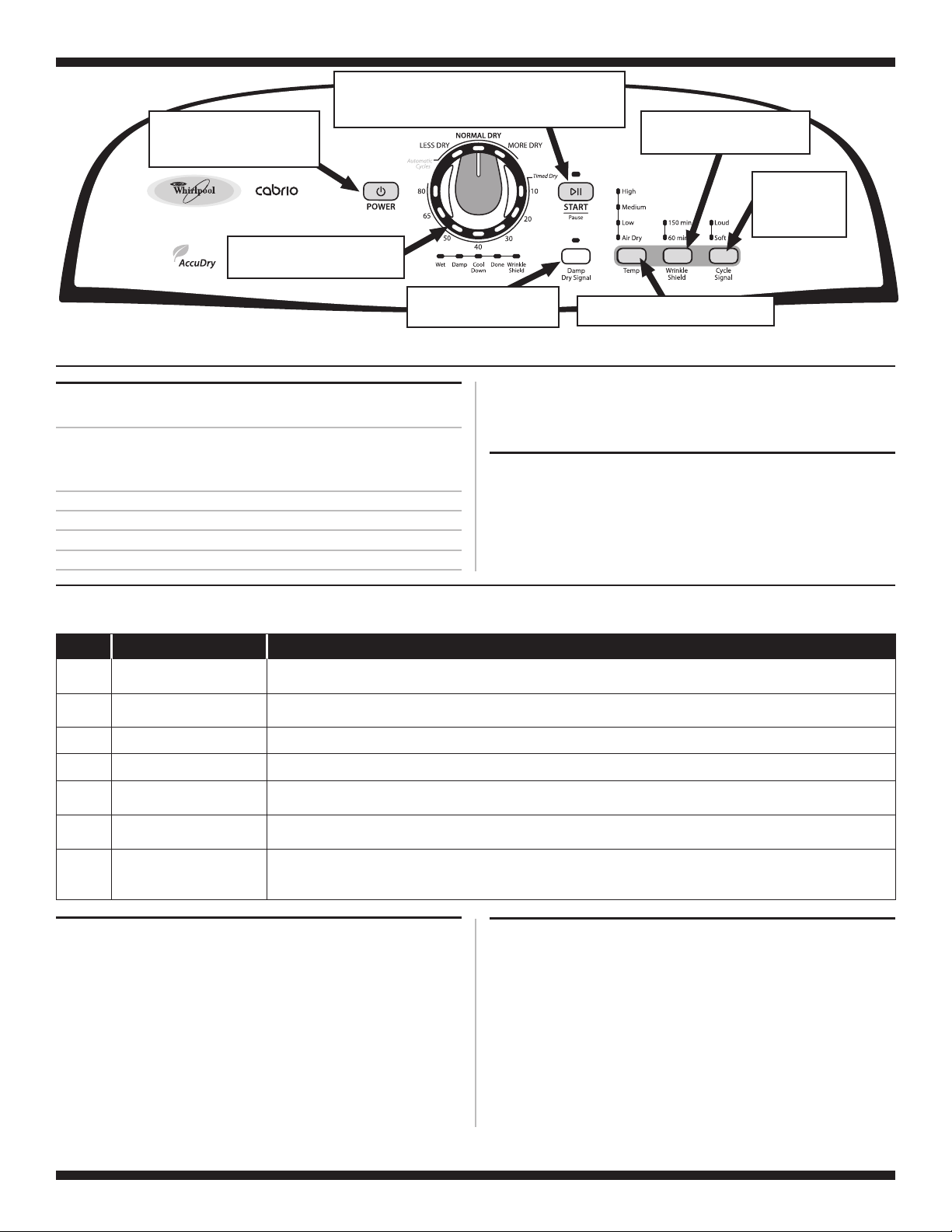
Figure 1. Console Diagnostics.
Not all features and options are available on all models. Appearance may vary.
Press 3 turns off the motor and heater.
➔➔
Toggles state of Damp Dry
indicator with each press.
On Off or Off On.
➔➔
Advancing Through Saved Fault/Error Codes
Procedure for advancing through saved fault codes:
Press and release
the 3rd button
used to activate
Service Diagnostics
Repeat
Repeat
Repeat
Repeat
beep tone➔Most recent fault code is displayed.
➔
➔
beep tone➔Second most recent fault code is displayed.
➔
beep tone➔Third most recent fault code is displayed.
➔
beep tone➔Fourth most recent fault code is displayed.
➔
Triple beep, then back to the most recent fault code.
Clearing Fault Codes
To clear fault codes, enter Service Diagnostic mode. Then press
and hold the 3rd button used to enter Service Diagnostic mode
for 5 seconds. Once the fault codes are successfully erased,
the WET indicator will be lit constantly.
➔
Toggles state of Wrinkle Shield
indicators with each press.
On Off or Off On.
Toggles state of Temp indicators with
each press. On Off or Off On.
Up to four Fault/Error codes may be stored. When the oldest fault code is
displayed, additional presses of the 3rd button will result in a triple beep, then a
cycling back to the most recent fault code. If each press of the 3rd button results
in a triple beep and the WET indicator is constantly lit, no saved fault codes are present.
➔➔
Toggles state of
Signal indicators
with each press.
On Off or
Off On.
➔➔
➔
➔
FAULT/ERROR CODES The fault codes below would be indicated when attempting to start a drying cycle, or after activating
the service diagnostic mode.
CODE DESCRIPTION EXPLANATION AND RECOMMENDED PROCEDURE
1 1
F E
2
F E
3
F E
3
F E
3
F E
3
F E
f4 e4
Primary Control Failure
Keypad/User Interface
1
1
2
Exhaust Thermistor Shorted
6
7
Moisture Sensor Shorted
Failure
Exhaust Thermistor Open
Moisture Sensor Open
Line Voltage Error
USER INTERFACE/CONTROL SYSTEM TEST
Entry Procedure:
Press and release the first button used to activate Service
Diagnostic mode. The following tests will be available.
NOTE: The Service Diagnostic mode must be activated before
activating the User Interface/Control System test; see procedure
on page 1.
Active Fault Code Display in User Interface/Control System Test:
If the wet indicator begins flashing while in User Interface/Control
System test, it is displaying an active fault code. Active fault codes
are codes that are currently failing. Only one active fault code can
be displayed at a time.
F1E1 indicates a primary control failure. Replace the machine control electronics. See Accessing & Removing the
Electronic Assemblies, page 11.
F2E1 indicates a stuck button or user interface mismatch. This fault code will ONLY appear when in the service diagnostic
mode. See TEST #5, page 10.
F3E1 indicates that the thermistor is open. See TEST #3a, page 8.
F3E2 indicates that the thermistor has shorted. See TEST #3a, page 8.
F3E6 indicates that the moisture sensor strip is open. This fault code will ONLY appear when in the service diagnostic mode.
See TEST #4, page 9.
F3E7 indicates that the moisture sensor strip has shorted. This fault code will ONLY appear when in the service diagnostic
mode. See TEST #4, page 9.
F4E4 indicates low line voltage detected. Check to see if a household fuse has blown or a circuit breaker has tripped.
Confirm the power cord is properly installed and plugged into the power outlet. Check the relay connections on the machine
control electronics. Gas Models Only: Check the P14 connection on the machine control electronics.
Diagnostic Test: Console Buttons and Indicators
Pressing buttons and rotating the cycle selector will turn off the
corresponding indicator and sound a beep as shown in figure 1,
Console Diagnostics. If indicators fail to come on and beep after
pressing buttons and rotating the cycle selector, go to TEST #5,
page 10.
NOTE: A second press of the Power button while in
Console Buttons and Indicators mode exits the Service
Diagnostic mode and returns the dryer to standby mode.
W10096965B .ON TRAPYLNO ESU S’NAICINHCET ECIVRES ROF
TECH SHEET - DO NOT DISCARD PAGE 3
Diagnostic Test: Door Switch
When the door is opened, for electric dryers,
the dryer will beep once and the WET status
indicator will turn on. For gas dryers, the
dryer will beep twice and the DONE status
indicator will turn on. With the door open,
the TEMP indicators will be used to display
the Control Software ID. The TEMP indicators
will be “On” or “Off” according to the table
below.
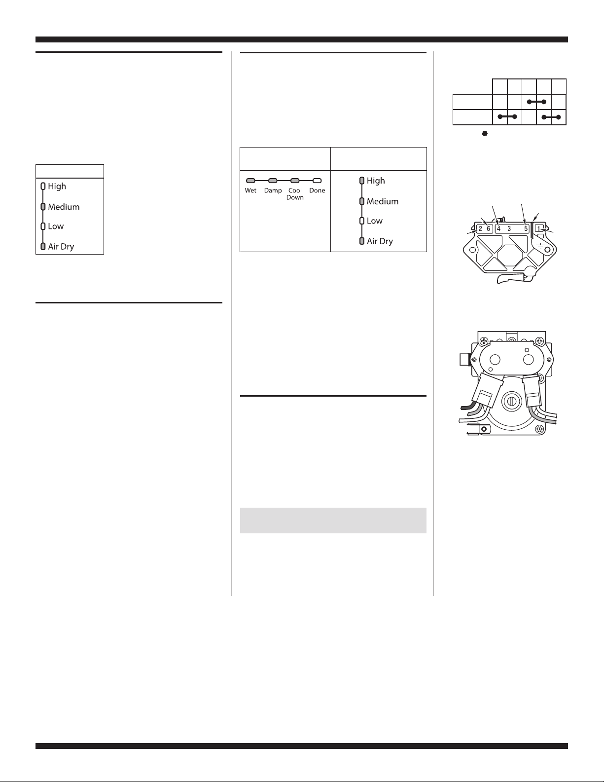
Temp Indicators
If opening the door fails to cause a beep(s),
Control Software ID, or fuel type to be indicated,
go to TEST #6, page 10.
Diagnostic Test: Moisture Sensor
Open the door and locate two metal strips
on the face of the lint screen housing. Bridge
these strips with a wet cloth or a finger. If a
beep is heard and STATUS and/or TEMP
indicators change, the sensor is OK. If not,
or if a beep tone is heard before bridging
the moisture strips, go to TEST #4, page 9.
Diagnostic Test: Console ID, Motor,
and Heater
Close the door. Press the START button. The
dryer will beep and the motor and heater will
turn on. The STATUS and TEMP indicators
will display the console ID, and the indicators
should be lit up as indicated in the table below.
Console ID Indicator Status Table
Status
Indicators
Temp
Indicators
While motor is running, pressing the START
button a second time will leave on the motor
and turn off the heater. A third press of the
START button will turn off both the motor
and the heater.
If the Console ID above is not displayed,
➔
replace the user interface assembly.
See Accessing & Removing the Electronic
Assemblies, page 11.
➔ If the motor does not turn on, go to
TEST #2, page 6.
➔ If no heat is detected, go to TEST #3, page 7.
DEACTIVATING TEST MODES
Deactivating the User Interface/
Control System Test
This mode can be exited by either of the two
methods listed below:
1. Pressing the POWER button twice.
2. Pressing and holding the 1st button used
to activate the Service Diagnostic mode
for 5 seconds.
Contacts
Function
Start
Run
Centrifugal Switch
Black-White
Red
Pluggable Drive Motor
Black
Blue
W HI T E
White
Gas Valve, Gas Dryer
1M 2M 3M 5M 6M
= Contacts closed
(Motor)
Blue-White (Elec)
White (Gas)
Lt. Blue
Switch
Green-Yellow
Red
White
Blue
DEACTIVATING THE SERVICE
DIAGNOSTIC MODE
Press and hold the 1st button used to enter
the Service Diagnostic mode for 5 seconds
to exit diagnostics.
W10096965B .ON TRAPYLNO ESU S’NAICINHCET ECIVRES ROF
TECH SHEET - DO NOT DISCARD PAGE 4
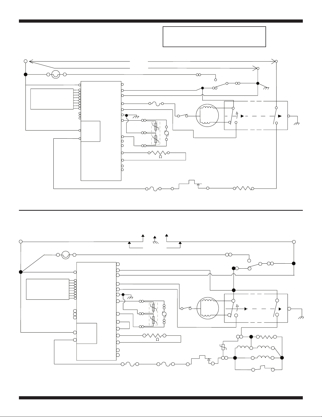
ELECTRIC DRYER WIRING DIAGRAM
L1 LINE - BK
BK
BK
BK
CONSOLE
ELECTRONICS
BK
DL1
DRUM LAMP
R
DL2
P9-2
VDD P1-8
DATA IN P1-7
VSS P1-6
STROBE P1-5
DATA OUT P1-4
CLOCK P1-3
BUZZER P1-2
+/- 12 VDC P1-1
N.O. 1
COM 1
BR
L1
P5-1 VDD
P5-2 DATA IN
P5-3 VSS
P5-4 STROBE
P5-5 DATA OUT
P5-6 CLOCK
P5-7 BUZZER
P5-8 +/- 12 VDC
P2-1 VDD
P2-2 DATA
P2-3 VSS
HEATER RELAY 1
HEATER +V
HEATER RTN
MACHINE
CONTROL
LAMP (N.C.)
DOOR
NEUTRAL
MOTOR
MTR CS
GND
MOIST.
MOIST RTN
MODEL
MODEL RTN
EXHAUST TEMP.
EXHAUST
TEMP RTN
N.C.
N.C.
P8-1
P8-4
P8-3 NEUTRAL
P9-1
P8-5 BK-W
P8-2
P13-2
P14-4
P14-5
P14-3
P14-6
P14-1
P14-2
240 VOLTS
120 VOLTS
LBU
G-Y
BK
P13-1
SENSOR MOVS
G-Y
R
R-W
R-W
R
IMPORTANT: Electrostatic (static electricity)
discharge may cause damage to machine
control electronics. See page 1 for details.
T
W
TF1
TF2
LBU
THERMAL FUSE
Y-R
SENSOR
10K
FH3
BK
TSG
HS1
BK
EXHAUST THERMISTOR
TS
FH1
THERMAL
CUT-OFF
W - NEUTRAL N
4M
BELT
SWITCH
NEUTRAL
HI LIMIT
THERMOSTAT
LBU
NC
P2
P3
LBU
NO
BU-W
MAIN
START
DRIVE MOTOR
1/3 H.P.
HS3
NC
DOOR
SWITCH
R-W
3M
P1
W
5M
CENTRIFUGAL SWITCH
6M
H2
HEATER
F1
H1
R - LINE L2
NEUTRAL
TERMINAL
LINKED TO
CABINET
W
R
R
2M
G-Y
1M
GAS DRYER WIRING DIAGRAM
L1 LINE - BK
BK
CONSOLE
ELECTRONICS
DL1
BK BR
STROBE P1-5
DATA OUT P1-4
CLOCK P1-3
BUZZER P1-2
+/- 12 VDC P1-1
BK
R
DRUM LAMP
P9-2
VDD P1-8
DATA IN P1-7
VSS P1-6
N.O. 1
COM 1
R
DL2
L1
P5-1 VDD
P5-2 DATA IN
P5-3 VSS
P5-4 STROBE
P5-5 DATA OUT
P5-6 CLOCK
P5-7 BUZZER
P5-8 +/- 12 VDC
P2-1 VDD
P2-2 DATA
P2-3 VSS
HEATER RELAY 1
HEATER +V
HEATER RTN
MACHINE
CONTROL
LAMP (N.C.)
DOOR
NEUTRAL
MOTOR
MTR CS
MOIST.
MOIST RTN
MODEL
MODEL RTN
EXHAUST TEMP.
EXHAUST
TEMP. RTN
GND
N.C.
N.C.
P8-1
T
P8-4
P8-3 NEUTRAL
P9-1
LBU
P8-5
BK-W
P8-2
G-Y
BK
P13-1
SENSOR MOVS
P13-2
R
P14-4
BK
P14-5
P14-3
P14-6
R-W
R-W
P14-1
P14-2
TF2
TF1
THERMAL FUSE
120 VOLTS
W
Y-R
DRAIN
BK
EXHAUST THERMISTOR
TS
R
10K
TSG
FH1
THERMAL
CUT-OFF
SENSOR
FH3
4M
SWITCH
BK
BELT
HS1
MAIN
LBU
START
DRIVE MOTOR
1/3 H.P.
HI LIMIT
THERMOSTAT
NC
VALVE
MOV
HS2
W - NEUTRAL N
5M
3M
BU
LBU
3V
P2
P3
NO
LBU
W
CENTRIFUGAL SWITCH
6M
BK
1V
2
HOLD
LBU
LBU
NC
DOOR
SWITCH
IG
BK
1
BK
ASSIST
4
FS1
FLAME SENSOR
P1
R
IGNITOR
MAIN
W
2M
G-Y
1M
R
IGR
W
3
VALVE NO.1
5
VALVE NO.2
W
FS2
W10096965B .ON TRAPYLNO ESU S’NAICINHCET ECIVRES ROF
 Loading...