

Whirlpool 6ALBR5233JQ0 User Manual

WHIRLPOOL CONSUMER SERVICES
October 2000
Model 6ALBR5233JQ0
WHIRLPOOL AUSTRALASIA
CONSUMER SERVICES
SERVICE MANUAL
TOP LOAD WASHING MACHINE
Model 6ALBR5233JQ0
Copyright © 2000 Whirlpool (Australia) Pty. Limited
All rights strictly reserved. Reproduction or issue to third parties in any form whatsoever is
not permitted without written authority of Whirlpool (Australia) Pty. Limited
Whirlpool is a registered trademark of Whirlpool U.S.A.
This documentation is intended only for qualified technicians who possess the required qualifications and
are aware of the regulatory requirements applicable to servicing electrical appliances.
Whirlpool (Australia) Pty Limited Part No. SM2057
A. B. N. 28 003 578 023

WHIRLPOOL CONSUMER SERVICES Model 6ALBR5233JQ0
Page 2 of 23
CONTENTS
Page
AUTOMATIC (ELECTRONIC) TEMPERATURE CONTROL 3 - 4
SERVICING THE ATC COMPONENTS 5
TESTING AND CHECKING ATC SYSTEM 5
TEST PROCEDURE 6
THERMISTOR RESISTANCE CHART 7
WATER LEVEL SWITCH 7
TOP AND CABINET PARTS 8 - 9
CONTROLS AND REAR PANEL PARTS 10 - 11
AGITATOR, BASKET AND TUB PARTS 12 - 13
BRAKE, CLUTCH, GEARCASE, MOTOR AND PUMP
PARTS
MACHINE BASE PARTS 16 - 17
WIRING HARNESS PARTS 18 - 19
BRAKE AND DRIVE TUBE PARTS 20
GEARCASE PARTS 21
14
WATER SYSTEM PARTS 22
MISCELLANEOUS PARTS 22
OPTIONAL PARTS (NOT INCLUDED) 23
WHIRLPOOL CONSUMER SERVICES Model 6ALBR5233JQ0
AUTOMATIC (ELECTRONIC) TEMPERATURE CONTROL - ATC (ETC)
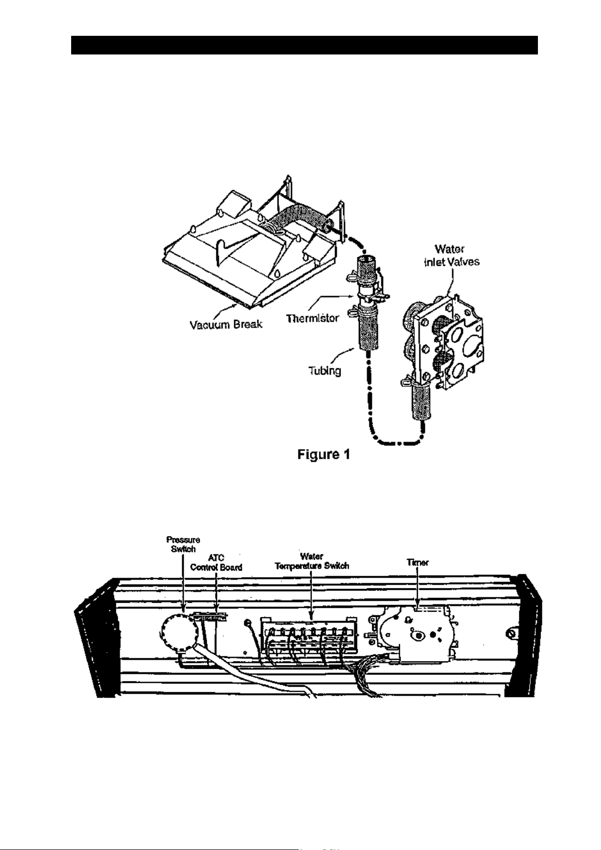
The ATC system controls the incoming water supply to provide an accurate setting for the
water temperature in the washing machine tub. The ATC system uses a thermistor located in
the water supply tubing between the water inlet valves and the and the vacuum break (See
Figure 1). The thermistor senses the incoming water temperature and provides input to the
ATC control board.
Page 3 of 23
The ATC control board uses the input from the thermistor to cycle the hot and cold water
solenoids on the water inlet valves to achieve the desired water temperature. A triac located on
the control board, cycles the hot and cold water solenoids through the water temperature switch
(See Figure 2).
Figure 2
The ATC system will provide 24°C ± 3°C For the COLD setting and 38°C ± 5°C For the WARM
setting.
WHIRLPOOL CONSUMER SERVICES Model 6ALBR5233JQ0
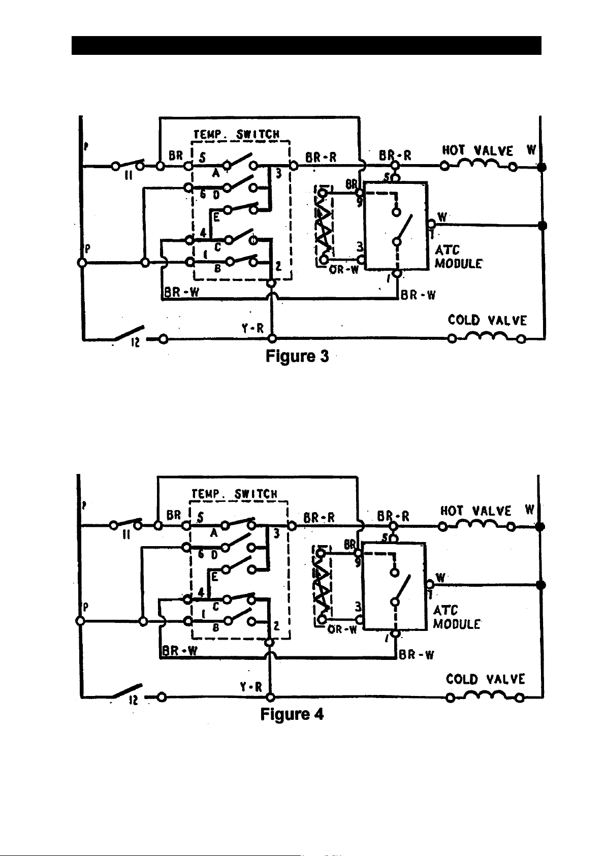
With the temperature selector switch set to COLD, the cold water solenoid energised for 100%
of the time and the hot water solenoid is cycled on and off (See Figure 3).
Page 4 of 23
With the temperature selector switch set to WARM, the hot water solenoid energised for 100%
of the time and the cold water solenoid is cycled on and off (See Figure 4).
Note : During the warm water fill, both solenoids are energised for 55 seconds. After
55 seconds, the hot water inlet valve stays on and the cold water inlet valve
cycles.
The ATC is only active during the wash fill, it has no effect on the rinse water temperature.
WHIRLPOOL CONSUMER SERVICES Model 6ALBR5233JQ0
SERVICING THE ATC COMPONENTS
1. To remove the ATC Control Board (See Figure 2 on Page 4), grip the sides of the board and
pull it straight out of its connector.
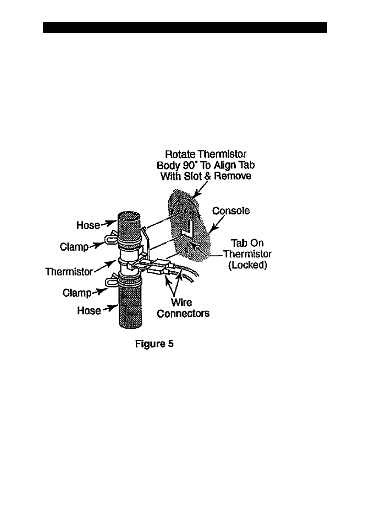
2. To remove the thermistor (See Figure 5) :
I. Disconnect the two wire connectors from the thermistor terminals.
II. Remove the two clamps from the hoses and pull the hoses off the connectors.
III. Pry the pins at the top at the top and bottom of the thermistor out of their console
holes and twist the body 90° in either direction. Pull the tab out of the console slot
and remove the thermistor.
Page 5 of 23
TESTING AND CHECKING ATC SYSTEM
The following steps test the ATC portion of the system.
Notes :
1. A properly operating ATC system will provide the following water temperatures in
the washer after the machine has filled with water ready for the wash operation :
Cold Wash : 24°°°°C ±±±± 3°°°°C
Warm Wash : 38°°°°C ±±±± 5°°°°C
2. The hot wash and all rinse water fills are not controlled by the ATC.
3. On cold wash setting Using gravity feed hot water systems may not allow the wash
water to achieve 24°°°°C ±±±± 3°°°°C.

WHIRLPOOL CONSUMER SERVICES Model 6ALBR5233JQ0
TEST PROCEDURE
1. Set the water temperature selector switch to Warm wash / Cold rinse.
2. Set the timer to the start of a wash cycle, start the machine and the tub will begin filling with
water.
3. Both the hot and cold inlet valves will operate continuously for approximately 55 seconds.
After the 55 seconds the hot water inlet valve should remain energised while the cold water
inlet valve will cycle on and off.
4. If the cold water inlet valve is not working properly :
• Disconnect the machine from the electrical supply.
• Check the ATC Control Board for proper installation in its connector.
• Make sure that the harness wires are in their proper location in the connector.
• Remove the ATC Control Board from its connector.
• Using an ohmmeter, measure the resistance of the thermistor at connector harness
wires 3 (OR-W) and 9 (BR). Compare the reading with the values in the “Thermistor
Resistance Chart” (See Page 8).
Page 6 of 23
If the ohmmeter readings are incorrect Remove and replace the thermistor and repeat
the test.
Notes :
I. If the hot water temperature is less than 49°°°°C, the cold water inlet valve
may turn off and stay off.
II. If the cold water temperature is above 21°°°°C, the cold water inlet valve will
stay on continuously.
III. If the thermistor is open-circuit, the cold water inlet valve will stay off. If
the thermistor is shorted, the cold water inlet valve will stay on
continuously.
5. Set the water temperature selector switch to Cold wash / Cold rinse.
6. Set the timer to the start of a wash cycle, start the machine and the tub will begin filling with
water.
7. The cold water inlet valve should remain energised while the hot water inlet valve will cycle
on and off. If the cold water temperature is above 18°°°°C, the hot water inlet valve may
not operate.
If the hot water inlet valve is not working properly disconnect the machine from the electrical
supply, replace the ATC Control Board and repeat steps 6. & 7.
WHIRLPOOL CONSUMER SERVICES Model 6ALBR5233JQ0
Thermistor Resistance Chart
Page 7 of 23
Temperature
°C
5 123.1 - 131.7
10 97.0 - 102.0
15 77.0 - 80.4
20 61.4 - 64.4
25 49.6 - 51.2
30 40.0 - 41.0
35 32.0 - 33.5
40 26.0 - 27.6
45 21.5 - 22.5
50 17.4 - 18.4
55 14.7 - 15.7
60 12.0 - 13.0
65 10.2 - 11.2
Resistance
kOhms
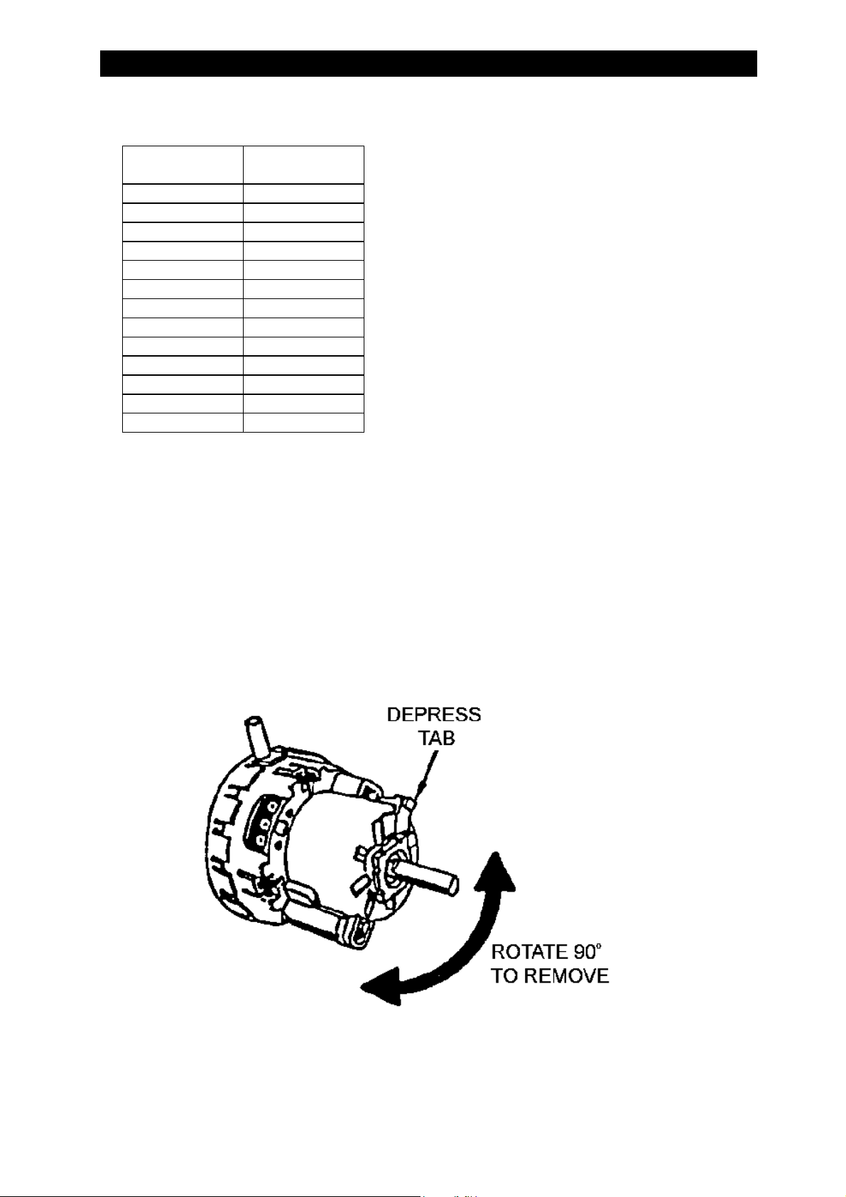
WATER LEVEL SWITCH
All new models are being fitted with a new water level switch constructed with a plastic body.
To remove the water level switch :
1.
Pull the knob off the switch shaft.
2.
Unplug the wiring harness connector from the switch assembly terminals and remove the
pressure switch tubing.
3.
Depress the tab and rotate the switch 90° and pull it from the console mounting plate.
Figure 6
 Loading...