

Page 1
Installation Instructions
ICE MAKER
Model 50
jve Ovens, Compactors, Room Air Conditioners, Dehumidifiers, Automatic Washers, Clothes Dryers, Freezers, Refrigerator-Freezers, Ice Makers,Dishwas
Page 2
Changing the bin door
and lower panel
The storage bin door is designed to accept an optional
decorative wood panel of your choice.
The wood panel should be no more than 'A inch (6 mm)
thick. Cut it to the same size as the production metal
panel. See Figure 1.
To change the bin door panel:
1. Open the bin door.
2. Remove the two screws on top of the door which
hold the handle.
3. Remove the handle.
4. Slide the metal panel out.
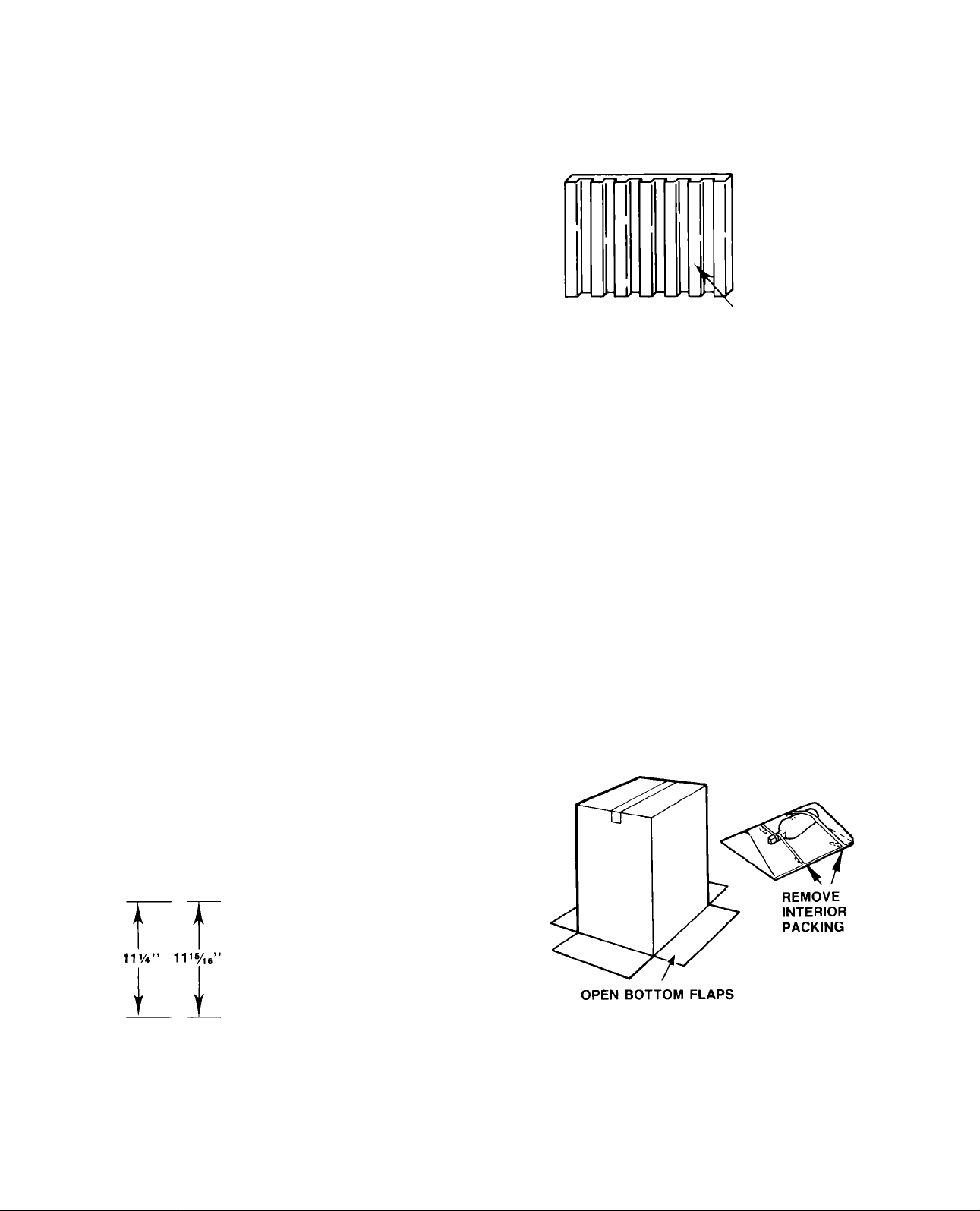
5. Break off the ribs on the door insulation to allow for
the wood thickness. See Figure 2.
6. Slide the wood panel into the door frame.
7. Replace handle and screws.
To change the lower panel:
1. Remove the two screws at the bottom that hold the
lower panel assembly to the ice maker.
2. Remove the two screws on the top of the panel
assembly.
3. Slide the metal panels and spacers out.
4. Slide the wood panel into the door frame.
REMOVE ALL DOOR INSULATION
RIBS TO ACCEPT WOOD PANEL
THICKNESS
FIGURE 2
Thermostat calibrations
If ice maker is installed above two thousand feet of
altitude, the bin and evaporator thermostats must be
adjusted to a warmer setting. Disconnect electricity,
remove thermostat and follow the directions for turn
ing the altitude adjustment screw as shown in the label
on each thermostat.
Shipboard operation
When this ice cube maker is installed aboard a ship,
it will be necessary to purchase and install a water
deflector. This deflector hangs between the lower edge
of the evaporator and the cutter grid. It keeps the water
flowing over the evaporator from spilling into the
storage bin area. Order the necessary parts from your
local ice maker dealer.
General information
Unpack
5. Replace the top of the panel assembly.
NOTE: Make sure the galvanized panel is replaced in
back of the panel assembly.
DOOR LOWER
BIN PANEL
WOOD
PANEL
DIMENSIONS
17”-
FIGURE 1
FIGURE 3
1. Lay carton on rear face and break open bottom flap.
2. Set carton upright with all four flaps outward. See
Figure 3.
3. Lift carton up and off of machine.
FIGURE 4
Page 3
Installation Instructions
4. Remove all tape and packaging material from the
outside and inside of the cabinet. See Figure 4.
5. Remove the front grill; take out the screws securing
the grill at the bottom and lift it free of cabinet.
6. Turn the fan by hand to make certain it moves freely.
7. Loosen thumb screws holding cutter grid and water
pan to “thumb tight.”
Utilities
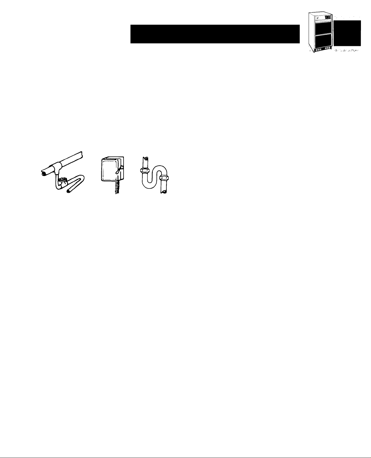
WATER
OBSERVE LOCAL CODES
Each installation is unique but will require:
1. A cold water inlet of Va” OD soft copper tubing and
a shut-off valve.
2. Either a gravity drain system or a sump pump to lift
the water to an existing drain.
3. An electrical branch circuit of 115 Volt, 60 Hz. 1
phase, with a 15 Amp delayed action fuse or circuit
breaker.
ELECTRICITY
DRAIN
Locate unit
2. Area should be well ventilated with temperature
above 55° F and below 110°F. Best results are ob
tained between 70°F and 90°F.
3. Provision for electricity, water and drain connections
should be determined.
4. The unit may be closed in on the top and three sides,
but the front MUST BE unobstructed for air circula
tion and proper operation. Installation should be
such that the cabinet can be moved forward for ser
vicing, if necessary.
Level unit
1. After placing unit in position, check to make certain
the unit is level side to side and front to back.
2. Accurate leveling is essential for proper operation.
3. Unit should be shimmed so that it is solid as well
as level. The shims should be of hard permanent
type material such as masonite.
4. Compliance with National Sanitation Foundation
standards require that this type of product be sealed
to the floor at the bottom rail in order to prevent con
tamination from spills or the entrance of vermin.
Therefore, we recommend that when installing this
product you seal it to the floor in accordance with
those standards. A silicone-type sealer is recom
mended.
For the plumber
Connect to water
(Observe local codes)
1. Use Va” OD soft copper tubing for the cold water
supply.
2. Provide a convenient manual shut-off valve in the
water line.
THIS UNIT MUST BE
INSTALLED IN AN
AREA PROTECTED FROM
THE ELEMENTS, SUCH
AS WIND, RAIN, WATER
SPRAY OR DRIP.
1. Place unit so the front side will be completely
unobstructed to provide proper air flow.
90“ F
70“ F
BEST
RANGE
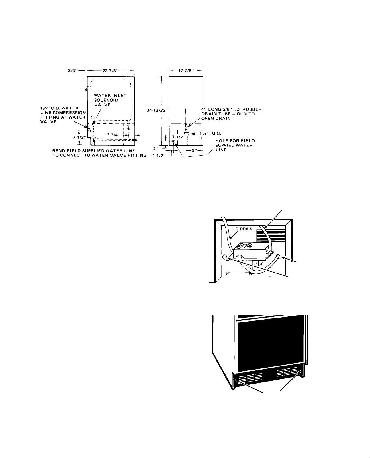
3. Position the tubing so it can enter the access hole
located in the right-hand rear of the cabinet. The tub
ing shoud extend beyond the cabinet front when the
cabinet is pushed back into position. See Figure 5.
NOTE:
Always purge the water line before making the final con
nection to the inlet of the water valve to prevent possi
ble water valve malfunction.
After the cabinet is in place, bend the tubing to meet
the connection at the water valve. The garden hose
threaded compression fitting is found in the parts bag.
This joint provides a convenient disconnect for service.
Be sure the tubing is clear of compressor, to prevent
rattle.
Page 4
RIGHT END VIEW
BACK VIEW
FIGURE 5
Connect the drain
(observe local codes)
1. The unit is provided with a gravity drain.
2. The ideal installation has a standpipe (IV4”
minimum) installed directly below the outlet of the
drain tube. Refer to figure 5 for the proper location
of the standpipe.
3. It may be desirable to insulate drain line thoroughly
up to drain inlet to minimize condensation on drain
tube.
Drain pump
1. When drain connection below the level of the unit
is not available a drain pump may be used to lift the
water to an available drain.
2. Install drain pump on floor behind ice maker with
discharge tube to the rear. Run bin drain directly
into pump as shown in Figure 5A.
3. Run power cord thru hole into unit compartment.
(See Figure 5A)
4. Remove lower grille assembly. (See Figure 5B)
ORDER DRAIN PUMP KIT NO. EKDP1 FROM
YOUR WHIRLPOOL DEALER
DRAIN PUMP HAS PRESSURE
SWITCH THAT CYCLES
ITS PUMP
FIG. 5A
ADD PLASTIC HOSE
FROM BIN DRAIN
DIRECTLY TO PUMP
5/, ID TUBE
POWER CORD
THRU THIS HOLE
■
FIELD SUPPLIED
WATER LINE
THRU THIS HOLE
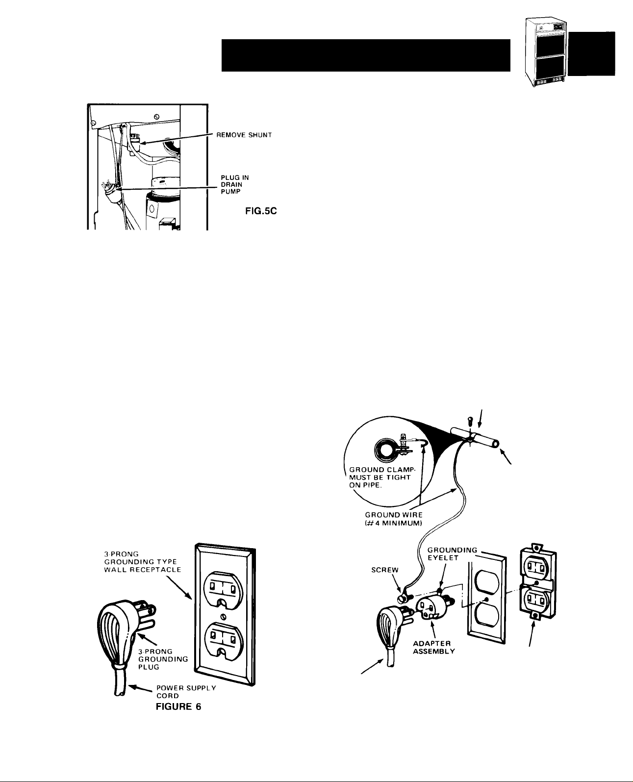
5. Remove shunt from receptacle and plug in drain
pump. (See Fugure 5C)
NOTE:
Do not discard shunt that is removed from
receptacie. This must be repiaced if unit is to
be operated without drain pump. See complete
installation instructions included with pump.
SCREWS
FIG. 5B
Page 5
Installation Instructions
For the electrician
Electrical requirements
A 115 Volt, 60 Hz, AC only, 15 Amp fused electrical
supply is required (time delay fuse or circuit breaker
is recommended). It is recommended that a separate
circuit, serving only this appliance, be provided. DO
NOT use an extension cord.
ELECTRICAL GROUND IS REQUIRED ON THIS
APPLIANCE.
Recommended grounding methods
DO NOT, UNDER ANY CIRCUMSTANCES, REMOVE
THE POWER SUPPLY CORD GROUND PRONG.
For your personal safety, this appliance must be
grounded. This appliance is equipped with a power
supply cord having a 3-prong grounding plug. To
minimize possible shock hazard, the cord must be
plugged into a mating 3-prong grounding type wall
receptacle, grounded in accordance with the National
Electrical Code and local codes and ordinances. If a
mating wall receptacle is not available, it is the personal
responsibility and obligation of the customer to have
a properly grounded 3-prong wall receptacle installed
by a qualified electrician. See Figure 6.
Alternate grounding method
DO NOT, UNDER ANY CIRCUMSTANCES, REMOVE
THE POWER SUPPLY CORD GROUND PRONG.
If changing and properly grounding the wall receptacle
is impossible and where local codes permit (consult
your electrical inspector), a temporary adapter may be
plugged into the existing 2-prong wall receptacle to
mate with the 3-prong power supply cord. See Figure
7. THIS, HOWEVER, IS NOT RECOMMENDED.
If this is done, you must connect the grounding eyelet
on the adapter to the wall receptacle cover plate screw
and from this same screw, you must connect a separate
copper ground wire (No. 4 minimum) to a grounded cold
water pipe*. See Figure 7. Do not ground to a gas supp
ly pipe. Do not connect to electrical supply until ap
pliance is permanently grounded.
*Cold water pipe must have metal continuity to elec
trical ground and not be interrupted by plastic, rubber
or other electrically insulating connectors (including
water meter or pump) without adding a jumper wire at
these connections.
GROUND ASSEMBLY
(ATTACH TO GROUNDED
COLD WATER PIPE)
ELECTRICALLY
GROUNDED COLD
WATER PIPE (REMOVE
PAINT, etc.)
3PRONG
GROUNDING
PLUG ^
POWER SUPPLY CORD
WALL RECEPTACLE
FIGURE 7
Page 6

How it works
• Compressor runs
• Condenser fan runs
• Water pump runs (circulates water)
• Cutter grid is warm to touch
WHEN THE DESIRED ICE SLAB
THICKNESS IS REACHED, THE
HARVEST CYCLE BEGINS AND THE
FOLLOWING HAPPENS:
• Evaporator thermostat is satisfied
• Compressor keeps running
• Condenser fan stops or turns very slowly
• Water pump stops
• As the room and water temperatures vary, so will the
amount of Ice produced. This means that higher
operating temperatures will result in reduced ice
production.
• The unit will shut off when Ice in the storage bin
touches the bin thermostat well and will automatical
ly cycle to keep the bin full.
• The storage bin is not refrigerated and some meltage
will occur. This, too, varies with the room
temperature.
• The unit needs good air circulation to perform effi
ciently. Keep the front grill and the condenser clean.
• The water system, including filter screen in the water
inlet solenoid valve, needs to be cleaned periodically
for good circulation. Instructions are located on the
Inner door panel.
Operating instructions
• Hot gas solenoid opens
• Water inlet valve opens
• Excess water Is flushed out of the drain pan
• Cutter grid is warm to the touch
NOTE: Normal harvest cycle takes 60 to 120
seconds.
MACHINE RESUMES FREEZING
AFTER SLAB IS RELEASED FROM
EVAPORATOR AND THE CUTTING
PROCESS BEGINS.
WHEN THE STORAGE BIN IS FILLED,
BIN THERMOSTAT OPENS.
• Cutter grid remains on
•
Things to
• For complete operating information, refer to the Use
and Care Guide.
• Before starting, wash out interior of cabinet with a
Baking Soda solution (2 tablespoons soda to a quart
of warm water). Rinse thoroughly.
• Make certain the water is turned on.
• Turn switch to the “ON” position.
IMPORTANT:
Allow unit to run for 3 hours before expecting
ice and for 24 hours before trying to set the
thickness control.
If installed above 2,000 feet altitude, see page 2 for
thermostat adjustments.
remember
• Water enters only during the defrost cycle. Therefore
the first cycle will be completed without water in the
system.
Page 7
Installation Instructions
Unit wiring diagram
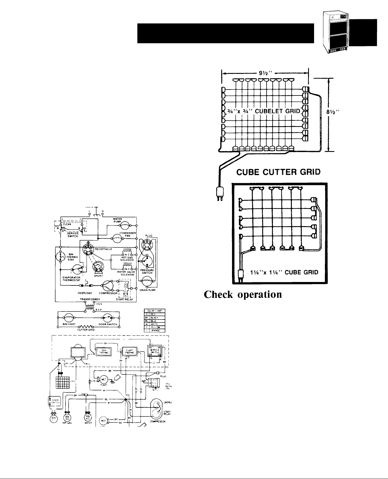
This model operates at 115 volts except for the cutter
grid circuit which operates at 8.5 volts at 1 amp.
The compressor runs at all times except when the bin
thermostat becomes satisfied and opens up. This de
energizes the system except for the transformer and
cutter grid.
Under normal operating conditions, when the
evaporator reaches the preset temperature (-i-10° to
-3° F, depending on thickness of ice) the evaporator
thermostat opens, terminating operation of the fan
motor and pump motor. The hot gas solenoid and the
water valve solenoid are energized at this time and re
main so until the evaporator reaches 38 -i- 2°F.
DANGER:
ELECTRIC SHOCK HAZARD disconnect power
before servicing unit. Maximum fuse size: 15
amps.
CUBELET CUTTER GRiDS
-------
g-C
Start the unit by turning the service switch to
“ON” and opening the line water valve.
NOTE: Left is “OFF” — Middle is “ON” — Right
is “CLEAN.” In “CLEAN” position, only the
pump operates.
Check condenser fan to make sure it is
revolving.
Water will not enter pump pan until freezing
plate gets cold and machine goes into a harvest
cycle.
Check for even water flow over freezing plate.
Unit must be level for proper operation.
Check for desired cube thickness and after 24
hours adjust if necessary. Maximum ice yield will
be obtained with ice thickness at V
Replace grill.
2” to
Page 8
Whirlpool
HOME APPLIANCES
Making your world a little easier.
In the event your WHIRLPOOL appliance should need service, call the dealer from w/hom you purchased
the appliance or a WHIRLPOOL franchised TECH-CARE® service company. He is in the Yellow Pages of
your telephone directory listed under "Appliances-Household-Major-Service and Repair." You can also
obtain his name and number by dialing, free, the Whirlpool COOL-LINE® Service (800) 253-1301. Dial
just as you normally dial long distance. A special operator will tell you the name and number of your
nearest Whirlpool TECH-CARE service outlet. During normal working hours. Whirlpool consultants at this
same number will also answer any questions about operating or maintaining your appliance not covered in
your Use and Care Guide.
Learn the benefits of using TECH-CARE service for maintaining the quality originally built into your
Whirlpool appliances.
Part No. 758934-U
lidifiers Automatic Washers, Clothes Dryers, Freezers, Refrigerator-Freezers, Ice Makers, Dishwashers, Built-In Dvens and Surface Units, Ranges, Microwi
Printed in U.S.A.
 Loading...