

Page 1

SERVICE MANUAL
for the
OVER-THE-RANGE
MICROWAVE OVEN HOOD
COMBINATION
1997 “E” Models
March, 1997
Printed in U.S.A. LIT4322167
Page 2

THIS MANUAL CONTAINS INFORMATION NECESSARY FOR SERVICING THE WHIRLPOOL MICROWAVE OVEN HOOD COMBINATION , MODELS:
MH7130XE
MH7135XE
MH9115XE
THE MANUAL IS DESIGNED TO BE USED ONLY BY
QUALIFIED SERVICE PERSONNEL. THE SERVICE
INFORMATION IS ORGANIZED TO HELP YOU EASILY FIND WHAT YOU NEED.
CHECK YOUR LOCAL BUILDING CODE FOR THE
PROPER MODE OF INSTALLATION. IN THE ABSENCE OF LOCAL CODES, THIS UNIT SHOULD BE
INSTALLED IN ACCORDANCE WITH THE
NATIONAL
ELECTRICAL CODE, ANSI/NFPA NO. 70 - 1990, OR
LATEST EDITION, OR C22.1 CANADIAN ELECTRICAL CODE, PART 1
.
This Microwave Service Manual is for authorized WHIRLPOOLSM service technicians only.
Because of the high voltage and the critical nature of the door closure system for the microwave
oven, Whirlpool recommends that customers DO NOT service their own microwave oven.
If you encounter problems with any Whirlpool range having a microwave feature, call your nearest
authorized WHIRLPOOLSM Service Company for service.
ii
Page 3

Cooking Products Service Manual
Original March, 1997 4322167
© 1997 Whirlpool Corporation
Page iii
TABLE OF CONTENTS
Page
Important Safety Information ...............................................................................................................................v
Theory Of Operation ......................................................................................................................................... 1-1
Component Access ........................................................................................................................................... 2-1
Component Sections .................................................................................................................................. 2-1
General ...............................................................................................................................................................
Removing The Microwave Oven & Cabinet ............................................................................................ 2-2
The Protection Control System .......................................................................................................................
Removing The Oven Door ......................................................................................................................... 2-4
Removing The Oven Door Components.................................................................................................. 2-5
Removing The Control Panel .................................................................................................................... 2-6
Removing The Line Fuse........................................................................................................................... 2-7
Removing/Adjusting The Interlock Switches .......................................................................................... 2-8
Removing The Base Thermal Fuse........................................................................................................ 2-10
Removing The Magnetron Thermal Fuse .............................................................................................. 2-11
Removing The Convection Thermistor .................................................................................................. 2-12
Removing The Cavity Thermal Fuse ..................................................................................................... 2-14
The Operating Control System......................................................................................................................
Removing The Oven Light Socket.......................................................................................................... 2-15
Removing The Control Circuit Board & The Turntable Indicator Circuit Board ..............................2-16
Removing The Fan Motor ........................................................................................................................ 2-17
Removing The Power Cord .....................................................................................................................2-18
Removing The Blower Motor Capacitor................................................................................................. 2-19
Removing The Convection Heating Element ........................................................................................ 2-20
Removing The Gas Sensor .....................................................................................................................2-22
Removing The Stirrer Motor .................................................................................................................... 2-23
Removing The Turntable Motor .............................................................................................................. 2-24
Removing The Cooktop Light Sockets ..................................................................................................2-25
The High Voltage Components .....................................................................................................................
Accessing The Components.................................................................................................................... 2-26
Removing The Magnetron .......................................................................................................................2-27
Removing The High Voltage Rectifier And The High Voltage Capacitor ......................................... 2-28
Removing The High Voltage Transformer............................................................................................. 2-29
2-2
2-4
2-15
2-26
iii
Page 4

Page
Component Description & Testing .................................................................................................................. 3-1
Important Safety Instructions .................................................................................................................... 3-1
The Thermal Fuses..................................................................................................................................... 3-4
The Blower Motor Capacitor ..................................................................................................................... 3-5
The Gas Sensor .......................................................................................................................................... 3-6
The Convection Thermistor ....................................................................................................................... 3-7
The Convection Heating Element............................................................................................................. 3-8
Motors ........................................................................................................................................................... 3-9
Programming Checks ............................................................................................................................... 3-10
Charts ......................................................................................................................................................... 3-11
Checking The Microwave Power Output ............................................................................................... 3-14
Checking For Microwave Energy Leakage ...........................................................................................3-15
Component Testing ..................................................................................................................................3-18
Control Circuit Board Checklist ..............................................................................................................3-23
Primary, Monitor, & Secondary Switch Checkout Procedure............................................................. 3-24
Tech Tips ............................................................................................................................................................ 4-1
Wiring Diagrams.......................................................................................................................................... 4-1
Strip Circuits ................................................................................................................................................ 4-3
Specifications .............................................................................................................................................. 4-6
Model & Serial Number Explanation ...................................................................................................... 4-15
Whirlpool Microwave Hood Warranty..................................................................................................... 4-16
iv
Page 5
IMPORTANT SAFETY INFORMATION
WARNING
This service manual is intended for factoryservice technicians only. We recommend that
customers DO NOT service their own units,
because of the complexity and risk of highvoltage electrical shock.
The following information is used throughout
this manual, and should be read carefully.
NOTE
Cooking Products Service Manual
Original March, 1997 4322167
© 1997 Whirlpool Corporation
Fire Hazard
Do not obstruct the flow of ventilation air.
Electrical Shock Hazard
It is the customer’s responsibility to:
• Contact a qualified electrical installer.
Page v
Helpful information that explains a more
complicated step, prior to carrying it out.
CAUTION
Information that will help you avoid actions
that could cause product damage (scratches,
dents, etc.) and damage to personal property.
WARNING
Information that alerts you to potentially
dangerous conditions. These conditions can
cause serious personal injury (burns, fire
and electrical shock, etc.) if the suggested
procedures are not observed.
• Assure that electrical installation is adequate and in conformance with the National Electrical Code, ANSl/NFPA 70—
latest edition*, and all local codes and
ordinances.
Failure to do so could result in fire, electrical
shock, or other personal injury.
Take special care when drilling holes into
the wall for venting or electrical wiring. Electrical wires may be concealed behind the
wall covering.
Failure to do so could result In fire, electrical shock, or other personal injury.
• National Fire Protection Association
Batterymarch Park
Quincy, Massachusetts 02269
WHIRLPOOL ASSUMES NO RESPONSIBILITY
FOR ANY REPAIRS MADE ON OUR PRODUCTS
BY ANYONE OTHER THAN AUTHORIZED
WHIRLPOOL SERVICE TECHNICIANS.
v
Page 6

CAUTION
WARNING TO SERVICE TECHNICIANS
To avoid possible exposure to microwave radiation or energy, visually check the oven for
damage to the door and door seal before
operating the oven. Use your microwave survey meter to check the amount of leakage
before servicing. In the event that the R.F.
Ieakage exceeds 4 mw/cm
ate repair must be made before continuing to
service the unit. Check interlock function by
operating the door latch. The oven cook cycle
should cut off before the door can be opened.
The door and latching assembly contains the
radio frequency energy within the oven. The
door is protected by three safety interlock
switches. Do not attempt to defeat them. Under no circumstances should you try to operate the oven with the door open.
2
at 5 cm, appropri-
• Proper operation of the microwave ovens
requires that the magnetron be properly
assembled to the waveguide and cavity.
Never operate the magnetron unless it is
properly installed.
• Be sure the “RF” seal is not damaged, and
assembled around the magnetron dome
properly when installing the magnetron.
• Routine service safety procedures should
be exercised at all times.
• Untrained personnel should not attempt
service without a thorough review of the test
procedures and safety information contained
in this manual.
PRECAUTIONS TO BE OBSERVED BEFORE AND DUR-
ING SERVICING TO AVOID POSSIBLE EXPOSURE TO
EXCESSIVE MICROWAVE ENERGY.
1. Do not operate or allow the oven to be
operated with the door open.
2. Make the following safety checks on all
ovens to be serviced before activating the
magnetron or other microwave source,
and make repairs as necessary:
a)Interlock Operation.
b)Proper Door Closing.
c) Seal and Sealing Surfaces (Arcing,
Wear, and Other Damage).
d)Damage to or Loosening of Hinges and
Latches.
e)Evidence of Dropping or Abuse.
3. Before turning on microwave power for
any service test or inspection within the
microwave generating compartments,
check the magnetron, wave guide or transmission line, and cavity for proper alignment, integrity, and connections.
4. Any defective or misadjusted components
in the interlock, monitor, door seal, and
microwave generation and transmission
systems shall be repaired, replaced, or
adjusted by procedures described in this
manual before the oven is released to the
owner.
5. A microwave leakage check to verify compliance with the Federal performance
standard should be performed on each
oven prior to release to the owner.
6. Do not attempt to operate the oven if the
door glass is broken.
vi
Page 7
CAUTION
WARNING
Whirlpool microwave ovens have a monitoring
system designed to assure proper operation
of the safety interlock systems.
Cooking Products Service Manual
Original March, 1997 4322167
© 1997 Whirlpool Corporation
Page vii
The interlock monitor switch will immediately
cause the oven fuse to blow if the door is
opened while the following combined failure
exists:
Primary door interlock switch and/or secondary interlock switch contacts failed in a closed
position.
CAUTION: REPLACE BLOWN
FUSE WITH 15 AMPERE CLASS H
FUSE ONLY.
Before replacing the blown oven fuse, test the
upper and lower door interlock switches, cook
relay or latch relay, and interlock monitor switch
(middle switch) for proper operation as described in the component test procedures.
DO NOT ATTEMPT TO REPAIR STICKING
CONTACTS OF ANY INTERLOCK SWITCH,
SAFETY SWITCH, OR COOK (LATCH) RELAY (REPLACE SWITCHES).
Any indication of sticking contacts during component test requires replacement of that component to assure reliability of the safety interlock system.
IF THE FUSE IS BLOWN, THE MONITOR,
PRIMARY INTERLOCK AND SECONDARY
INTERLOCK SWITCHES MUST ALSO BE
REPLACED. BE SURE THEY ARE PROPERLY CONNECTED.
NOTES:
• For proper repair and assembly of the oven
door, refer to pages 2-4 and 2-5.
• Interlock switches are not adjustable individually.
• For proper repair and adjustment of the
interlock switches, refer to page 2-8.
DISCONNECT FROM POWER SUPPLY
BEFORE SERVICING.
CAUTION: HIGH VOLTAGES ARE
PRESENT DURING THE COOK
CYCLE. EXTREME CAUTION
SHOULD BE OBSERVED AT ALL
TIMES.
CAUTION: DO NOT TOUCH
OVEN COMPONENTS OR WIRING DURING OVEN OPERATION.
ATTACH METER LEADS WITH
ALLIGATOR CLIPS WHEN MAKING OPERATIONAL TESTS.
CAUTION: IT IS NEITHER NECESSARY NOR ADVISABLE TO
ATTEMPT MEASUREMENT OF
HIGH VOLTAGES.
CAUTION: BEFORE TOUCHING
ANY OVEN COMPONENTS OR
WIRING, ALWAYS UNPLUG THE
OVEN FROM ITS POWER
SOURCE AND DISCHARGE THE
CAPACITOR BY USING A
20,000-OHM DISCHARGE RESISTOR.
USE AN INSULATED PLASTICHANDLE SCREWDRIVER AND
SHORT ACROSS THE CAPACITOR TERMINALS.
OR
vii
Page 8

R.F. LEAKAGE TEST
CAUTION
EQUIPMENT
• Electromagnetic energy leakage monitor
(NARDA 8100B, HOLADAY H1501).
• 600 ml glass beaker.
• Glass thermometer 100°C or 212° F.
TEST
On every service call, checks for microwave
energy emission must be made according to
the following manner.
1. Remove the cooking rack from the oven
cavity, if the microwave oven is so
equipped.
2. Place a 250 ML (8.0 oz.) glass of water in
the center of the oven bottom.
3. Select “HIGH” cook power, turn the mi-
crowave oven on, and test for R.F. Ieakage
at the following locations using the pattern shown below:
a) Around the cabinet at the front.
b) Around the door.
c) Across the console panel.
d) Horizontally across the door.
e) Vertically across the door.
f) Diagonally across the door.
g) Across the air vents.
h) Across the rear air vent.
i) All lockseams.
j) Weld at bottom.
k) Bottom plate.
I) Oven feet.
4. The scan speed is one inch per second.
When checking for R.F. Ieakage, use an approved R.F. measuring device to assure less
than 4 mw/cm
a maximum scan rate of 2.5 cm/second, in
compliance with U.S. Government Department
of Health, Education and Welfare 21 CFR1030,
performance Standard for Microwave Ovens.
A properly operating door and seal assembly
will normally register small emissions, but they
must be no greater than 4 mw/cm
measurement uncertainty.
NOTE: Enter leakage readings in space BEFORE and AFTER on the service document.
All microwave ovens exceeding the emission
level of 4 mw/cm
Service for microwave ovens immediately and
the owner should be told not to use the microwave oven until it has been repaired completely.
If a microwave oven is found to operate with
the door open, report to Dept. of Service, the
manufacturer and CDRH* immediately. Also
tell the owner not to use the oven.
* CDRH: Center for Device and Radiological Health, Food
and Drug Administration.
The interlock monitor switch acts as the final
safety switch protecting the customer from
microwave radiation. If the interlock monitor
switch operated to blow the fuse when the
interlocks failed you must replace all interlock
switches—primary and secondary interlock
switches and the monitor switch with new
ones because the contacts of those interlock
switches may be melted and welded together.
All repairs must be performed in such a manner that microwave energy emissions are minimal.
Address for CDRH is:
Office of Compliance (HFZ-312) Center for
Devices and Radiological Health
1390 Piccard Drive
Rockville, Maryland 20850
2
emission at 5 cm distance with
2
to allow for
2
must be reported to Dept. of
viii
Page 9
THEORY OF OPERATION
Cooking Products Service Manual
Original March 1997 4322167
© 1997 Whirlpool Corporation
Page 1-1
The microwave oven is powered by the 120volt line. Whenever the door is closed and a
cooking function is programmed through the
control panel’s keypad, relay contacts on the
control board close, and complete a circuit
from the L1 side to the neutral side of the line.
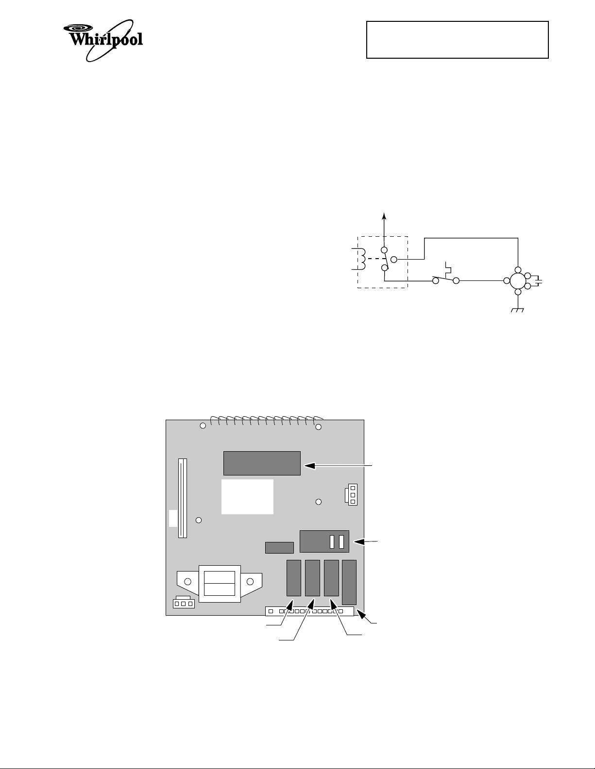
The control board uses five relays to operate
the various functions of the microwave oven
Relay 4 controls the speed of the blower motor
through the contol panel. The base thermal
fuse will also turn the blower motor on to its
low speed if the temperature reaches 133˚F.
The schematic configuration for relay 4 is
shown in the following diagram. The relay is
explained in further detail on the following
page.
L1
(see below). The relays are controlled by the
microcomputer on the control board, and per-
(NC)
(C)
(NO)
form the functions shown below.
RELAY 4
Relay 1 ........................................................ Oven Light/Fan & Stirrer Motors
Relay 2 ........................................................ High Voltage Section
Relay 3 ........................................................ Low-Speed Blower Motor
Relay 4 (N.C. Contacts) ........................... Auto Low-Speed Blower Motor
Relay 4 (N.O. Contacts) ........................... High-Speed Blower Motor
Relay 5 ........................................................ Turntable Motor
BASE
THERMAL
FUSE
BLOWER
MOTOR
(LOW)
(HI)
(C)
CN3
CONTROL
CIRCUIT
BOARD
RELAY RY1
RELAY RY5
MICROCOMPUTER
RELAY RY2
RELAY RY4
RELAY RY3
1-1
Page 10
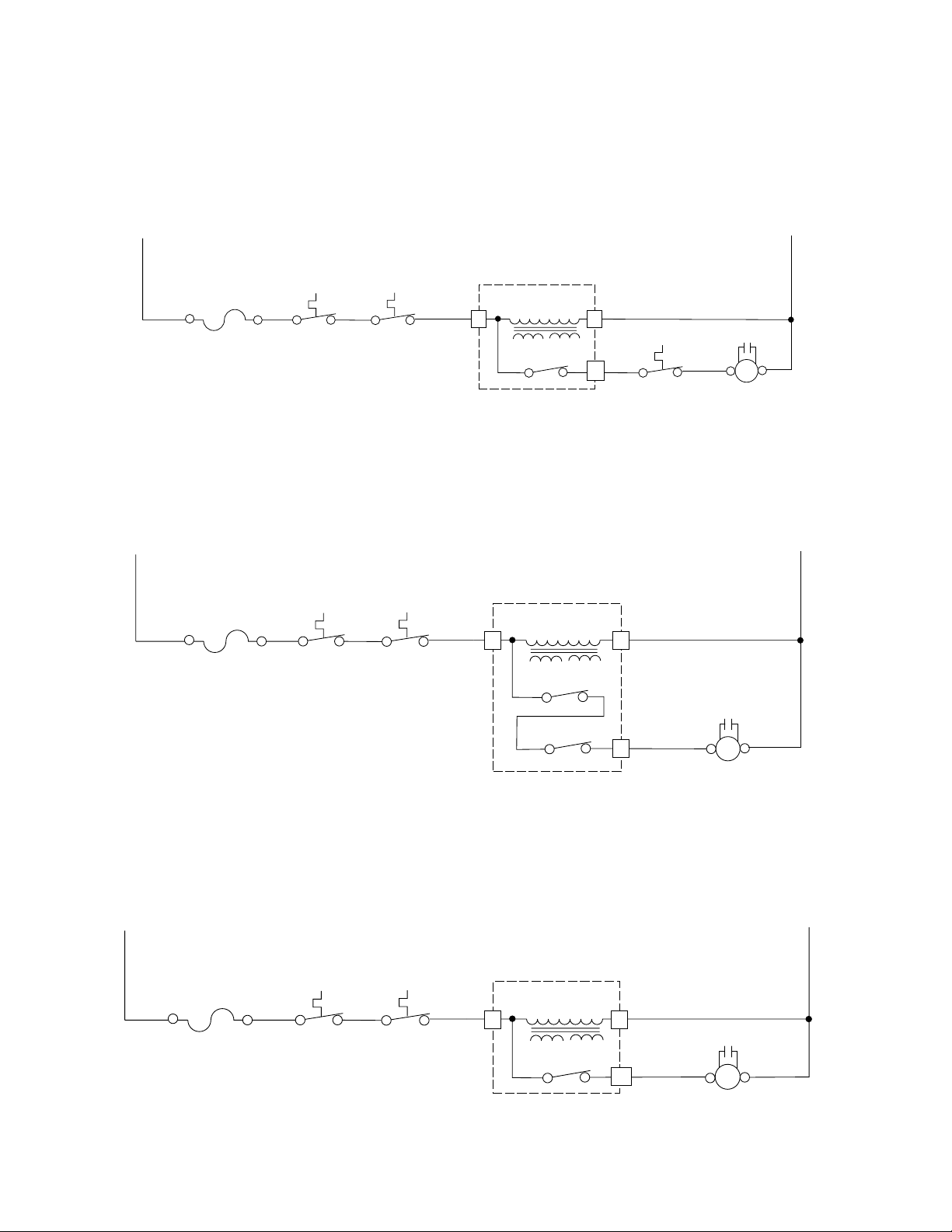
The normally-closed (N.C.) contacts of relay 4 provide a potential circuit for the Base Thermal
Fuse. If the base of the oven exceeds 133˚F, the thermal fuse contacts close, and a circuit for
the low-speed side of the blower motor is completed, which turns the motor on. The low-speed
blower will operate until the base temperature drops below 104˚F and opens the thermal fuse
contacts, and turns off.
L1
BK
20A LINE
FUSE
BK
MAGNETRON
THERMAL
FUSE
BK
CAVITY
THERMAL
FUSE
MICROCOMPUTER
RD
TRANSFORMER
3 1
BOARD
LOW-VOLTAGE
RELAY 4
11
YL
THERMAL
BASE
FUSE
W
CAPACITOR
RD RD
W
BLOWER
MOTOR
N
BL
(C)(HIGH)
When the low-speed fan is selected by the user at the control panel, relay 3 and the normallyclosed (N.C.) contacts of relay 4, complete the circuit to the low-speed windings of the blower
motor and turn it on.
L1
20A LINE
FUSE
RDBK
MAGNETRON
THERMAL
FUSE
BK
CAVITY
THERMAL
USE
MICROCOMPUTER
LOW-VOLTAGE
RD
TRANSFORMER
3 1
BOARD
RELAY 4
RELAY 3
W
CAPACITOR
9
PK/W
(LOW)
BLOWER MOTOR
RDRD
(C)
N
BL
When the high-speed fan is selected by the user at the control panel, the normally-open (N.O.)
contacts of relay 4 complete the circuit to the high-speed windings of the blower motor and turn
it on.
L1
BK
20A LINE
FUSE
RD
MAGNETRON
THERMAL
FUSE
BK
CAVITY
THERMAL
FUSE
MICROCOMPUTER
RD
TRANSFORMER
3 1
BOARD
LOW-VOLTAGE
RELAY 4
13
W
CAPACITOR
RDRD
BK
(HI) (C)
BLOWER MOTOR
N
BL
1-2
Page 11
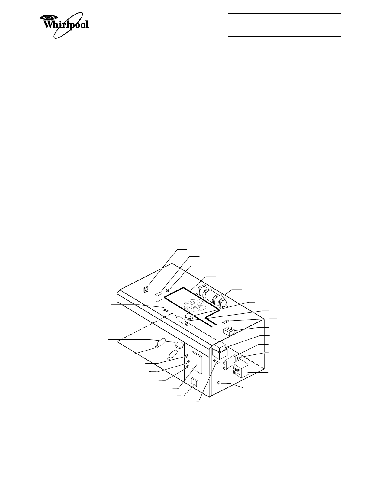
COMPONENT ACCESS
COMPONENT SECTIONS
This section instructs you on how to service
the individual components in the Microwave
Oven Hood Combination. These components
(shown below) and their sections are as follows:
• General
Cabinet
• The Protection Control System
Oven Door
Oven Door Components
Control Panel
Line Fuse
Interlock Switches
Base Thermal Fuse
Magnetron Thermal Fuse
Convection Thermistor
Cavity Thermal Fuse
Cooking Products Service Manual
Original March, 1997 4322167
© 1997 Whirlpool Corporation
Page 2-1
• The Operating Control System
Oven Light Socket
Control Circuit Board
Turntable Indicator Circuit Board
Fan Motor
Power Cord
Blower Motor Capacitor
Convection Heating Element
Gas Sensor
Stirrer Motor
Turntable Motor
Cooktop Light Socket
• The High Voltage Components
Magnetron
Rectifier
Capacitor
Transformer
Refer to the section on the following pages for
the component you wish to service.
GAS SENSOR (NOT ON ALL MODELS)
BLOWER MOTOR CAPACITOR
CAVITY THERMAL FUSE
CONVECTION HEATING ELEMENT
(NOT ON ALL MODELS)
BLOWER MOTOR
CONVECTION THERMISTOR
(NOT ON ALL MODELS)
TURNTABLE MOTOR
COOKTOP LIGHTS
SECONDARY INTERLOCK SWITCH
INTERLOCK MONITOR SWITCH
PRIMARY INTERLOCK SWITCH
CONTROL CIRCUIT BOARD
TURNTABLE INDICATOR CIRCUIT BOARD
LINE FUSE
STIRRER MOTOR
OVEN LIGHT
MAGNETRON
THERMAL FUSE
FAN MOTOR
MAGNETRON
HV CAPACITOR
HV RECTIFIER
HV TRANSFORMER
BASE THERMAL FUSE
Base Thermal Fuse ................................................. Closes @ 133˚F/56˚C, resets @ 104˚F/40˚C.
Magnetron Thermal Fuse ...................................... Opens @ 228˚F/109˚C, resets @ 140˚F/60˚C.
Cavity Thermal Fuse .............................................. Opens @ 230˚F/110˚C, resets @ 140˚F/60˚C.
2-1
Page 12
GENERAL
REMOVING THE MICROWAVE OVEN & CABINET
WARNING
Personal Injury Hazard
Disconnect from the electrical supply before servicing the unit. Failure to do so
could result in death or electrical shock.
IMPORTANT NOTE: Most of the microwave
components can be serviced without removing the unit or its cabinet. They can be accessed by removing the vent grille and the
control panel. Before removing the unit or its
cabinet, first check the procedure for the component you wish to service to see if it is necessary. If it is necessary to remove the unit and
its cabinet to service a component, use the
following procedure.
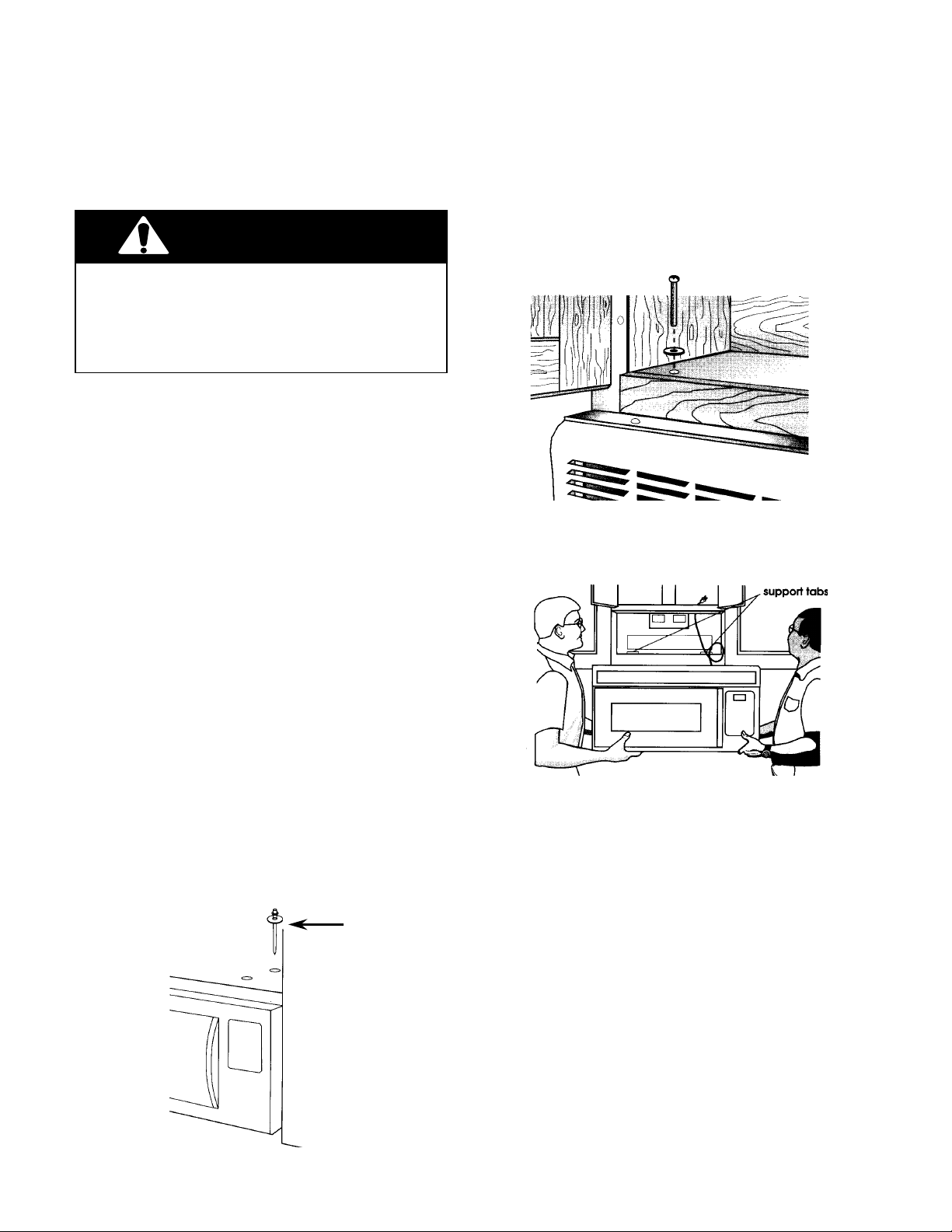
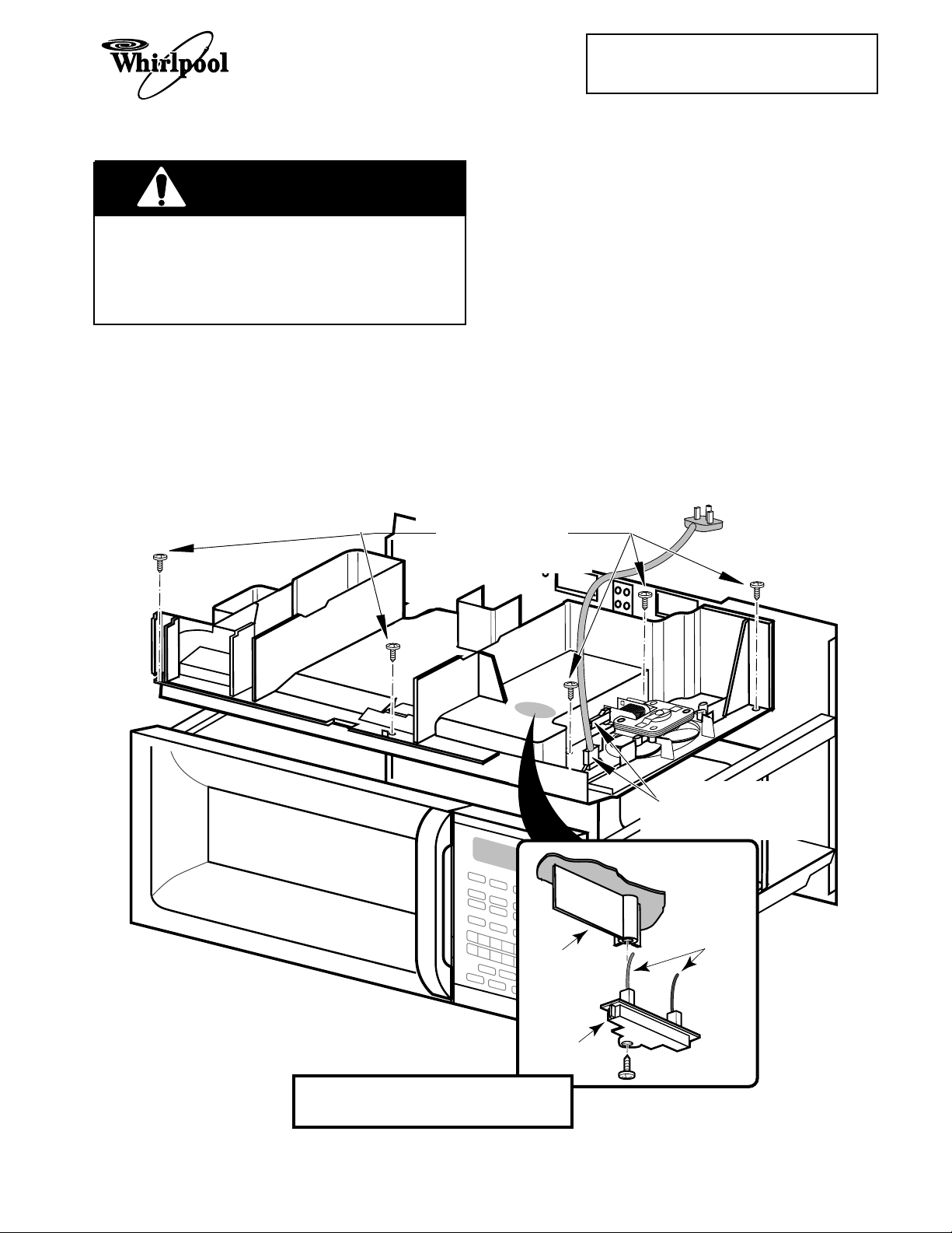
4. Support the front of the microwave oven
and remove the two bolts and washers
from the top of the oven.
5. Using two people, remove the microwave
oven from its mounting location and set it
on a protected (padded) work surface.
CAUTION: Because of the weight and size of
the microwave oven, two people are required
to safely move and install it. Failure to do so
could result in personal injury.
1. Disconnect the electrical supply to the
microwave oven.
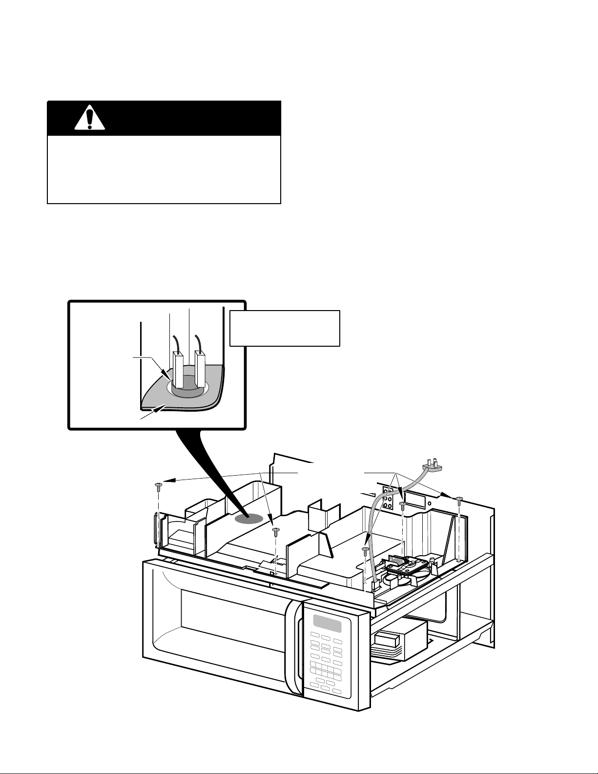
2. Remove the six screws from the base
plate and lower it, (see the illustration on
the next page), then disconnect the
cooktop light connector, and set the base
plate aside.
3. Remove the lock pin and washer from the
top of the microwave oven.
LOCK PIN &
WASHER
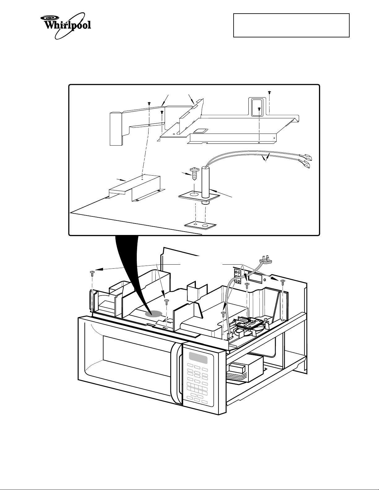
6. To remove the vent grille from the microwave oven, remove the two inside screws
from the top of the cabinet, then pull the
top of the vent grille out so the two center
tabs are free of their slots, and remove
the grille.
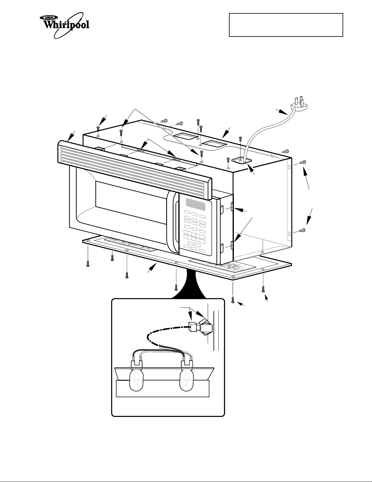
7. Remove the screw from the power cord
cover and remove the cover.
8. Remove the remaining screws from the
top and rear of the cabinet.
9. Slide the cabinet back and unhook the
sides from the tabs, then slide the power
cord out of the cabinet, and remove the
cabinet.
Proceed to the section for the component you
wish to service.
2-2
Page 13
VENT
GRILLE
CABINET
SCREW
VENT
GRILLE
SCREWS (2)
TAB SLOTS
Cooking Products Service Manual
Original March, 1997 4322167
© 1997 Whirlpool Corporation
CABINET
Page 2-3
POWER
CORD
POWER
CORD COVER
CABINET
SCREWS
BASE
PLATE
CONNECTORS
SLOTS
BASE PLATE
SCREWS
(6)
COOKTOP LIGHT
ASSEMBLY WIRING
Removing The Cabinet
2-3
Page 14
THE PROTECTION CONTROL SYSTEM
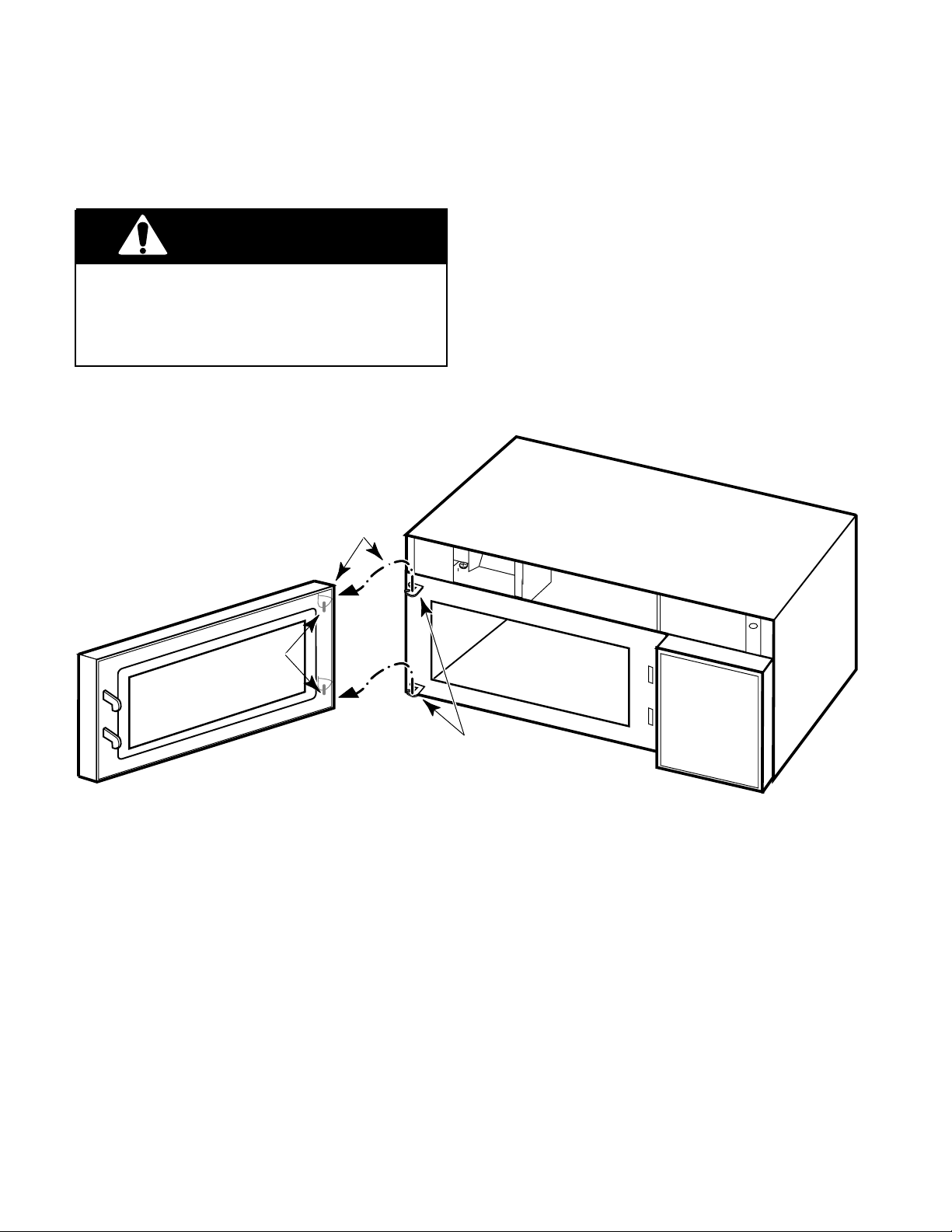
REMOVING THE OVEN DOOR
WARNING
Personal Injury Hazard
Disconnect from the electrical supply before servicing the unit. Failure to do so
could result in death or electrical shock.
1. Disconnect the electrical supply to the
microwave oven.
LIFT DOOR PINS
OUT OF HINGE HOLES
2. Remove the two screws from the top of
the cabinet for the vent grille and remove
the grille (see the illustration on page 2-3).
3. Open the oven door all the way, then lift
the door pins out of the hinge holes and
remove it.
4. Install the new oven door and the vent
grille on the microwave oven.
PINS
HINGES
2-4
Page 15
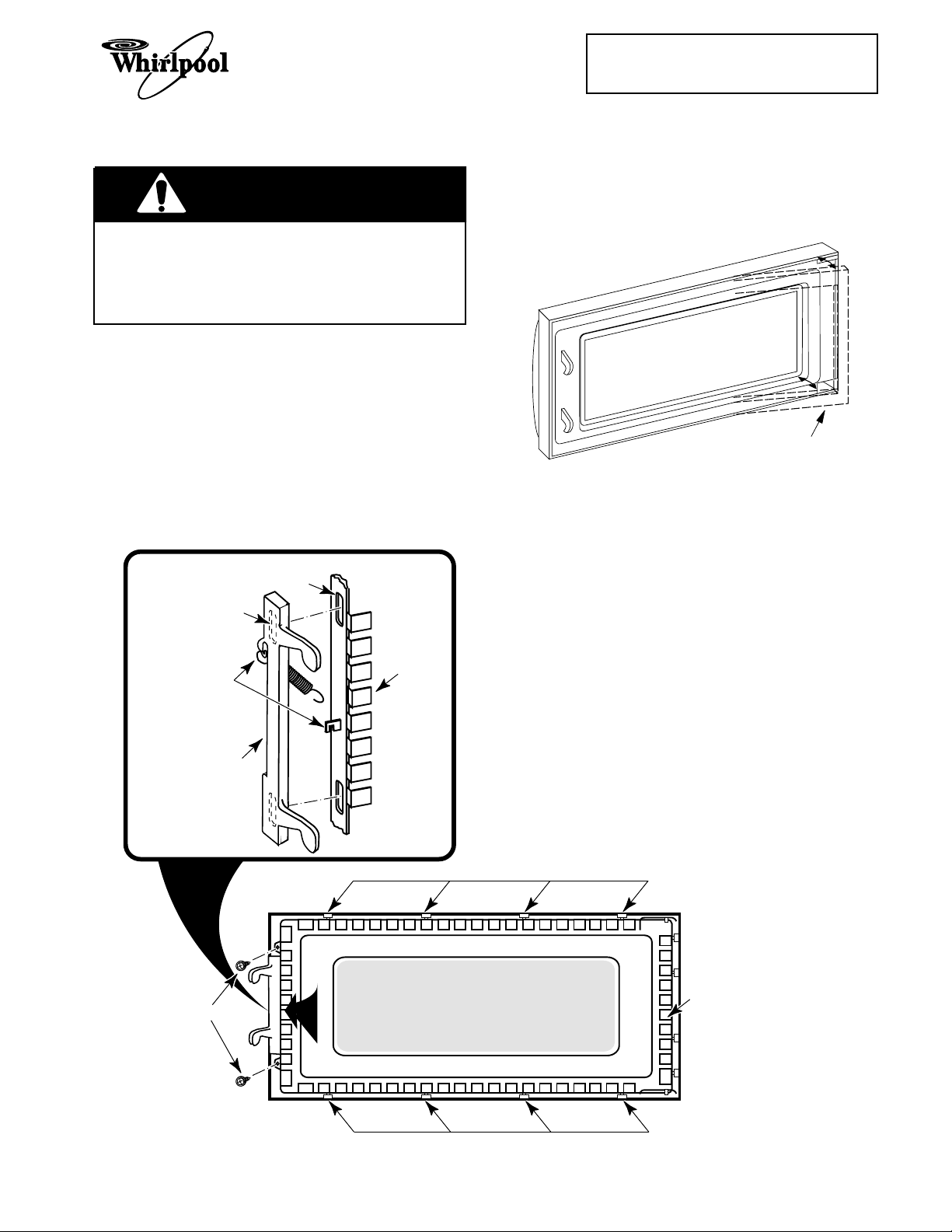
REMOVING THE OVEN DOOR COMPONENTS
WARNING
Personal Injury Hazard
Disconnect from the electrical supply before servicing the unit. Failure to do so
could result in death or electrical shock.
Cooking Products Service Manual
Original March, 1997 4322167
© 1997 Whirlpool Corporation
Page 2-5
4. To remove the oven door choke, use a
putty knife along the edges, and pry the
choke out from around the inside window
frame.
1. Disconnect the electrical supply to the
microwave oven.
2. Remove the two screws from the top of
the cabinet for the vent grille and remove
the grille (see the illustration on page 2-3).
3. Open the oven door all the way, then lift
the door pins out of the hinge holes and
remove it (see the illustration on the previous page).
SLOT
HOOKED TAB
GLASS
HOOK SPRING
OVER TABS
LATCHES
FRAME
OVEN DOOR
PRY OUT CHOKE
5. To replace the latches and door glass
assembly, remove the two mounting
screws from the end of the glass frame,
then push the top and bottom edges of the
door out and unsnap the locking tabs from
the frame and remove the assembly.
6. Slide the latches down and remove the
hooked tabs from the slots in the door
frame, then unhook the ends of the spring
from the door, and remove the latches.
7. Reassemble the oven door.
8. Reinstall the oven door and vent grille on
the microwave oven.
FRAME SCREWS
TOP LOCKING TABS
GLASS
FRAME
BOTTOM LOCKING TABS
2-5
Page 16
REMOVING THE CONTROL PANEL
WARNING
Personal Injury Hazard
Disconnect from the electrical supply before servicing the unit. Failure to do so
could result in death or electrical shock.
2. Remove the two screws from the top of
the cabinet for the vent grille and remove
the grille (see the illustration on page
2-3).
3. Remove the screw from the top center tab
of the control panel, then lift the panel so
that the bottom tabs are out of the slots
and pull it forward.
1. Disconnect the electrical supply to the
microwave oven.
TURN PANEL OVER
CONTROL PANEL
4. Turn the panel over and disconnect the
three harness connectors from the board,
then set the control panel aside.
CONTROL
PANEL SCREW
BOTTOM
TABS
BOTTOM
SLOTS
2-6
Page 17
REMOVING THE LINE FUSE
WARNING
Personal Injury Hazard
Disconnect from the electrical supply before servicing the unit. Failure to do so
could result in death or electrical shock.
Cooking Products Service Manual
Original March, 1997 4322167
© 1997 Whirlpool Corporation
Page 2-7
2. Remove the two screws from the top of
the cabinet for the vent grille and remove
the grille (see the illustration on page
2-3).
3. Remove the control panel from the microwave oven (see page 2-6).
4. From inside the control panel opening,
unsnap and open the fuseholder halves.
1. Disconnect the electrical supply to the
microwave oven.
CONTROL PANEL
OPENING
5. Remove the line fuse from the fuseholder
and pull the wire connectors off the ends.
6. Install the new line fuse and reassemble
the microwave oven.
2-7
SLIDE WIRE CONNECTORS
OFF ENDS OF FUSE
LINE FUSE
OPEN FUSEHOLDER
SECTIONS
FUSE HOLDER
Page 18
REMOVING/ADJUSTING THE INTERLOCK SWITCHES
6. One at a time, pull the wire connectors off
WARNING
Personal Injury Hazard
Disconnect from the electrical supply before servicing the unit. Failure to do so
could result in death or electrical shock.
REMOVING A SWITCH
1. Disconnect the electrical supply to the
microwave oven.
2. Remove the two screws from the top of
the cabinet for the vent grille and remove
the grille (see the illustration on page
2-3).
3. Remove the control panel from the microwave oven (see page 2-6).
4. Remove the two mounting screws from
the interlock switch assembly, and position the assembly so you can easily access the switches and wiring.
5. Refer to inset 1 on the next page for the
secondary interlock switch, or inset 2 for
any of the other switches mounted on the
interlock switch housing assembly, and
remove the switch from the housing as
shown.
CONTROL PANEL
OPENING
the defective switch, and reconnect them
to the same terminals on the replacement
switch.
7. Snap the new switch into place on the
switch housing.
8. Mount the interlock switch assembly to
the chassis flange with two screws.
9. Close the housing cover and secure it
with its mounting screw.
MAKING ADJUSTMENTS
1. Plug in the microwave oven and check the
operation of the switches. If necessary,
loosen the two housing screws, and adjust the housing so that the switches operate properly. NOTE: The Interlock Monitor
Switch provides an added safety check on
the Primary and Secondary Interlock
Switches. If the Primary and Secondary
Interlock Switches allow the oven to operate with the door open, the Interlock Monitor Switch will blow the line fuse. Unplug
the oven again when you have completed
the checks.
2. Reassemble the microwave oven.
INTERLOCK
2-8
SCREW
INTERLOCK
SWITCH
HOUSING
INTERLOCK
SCREW
Page 19
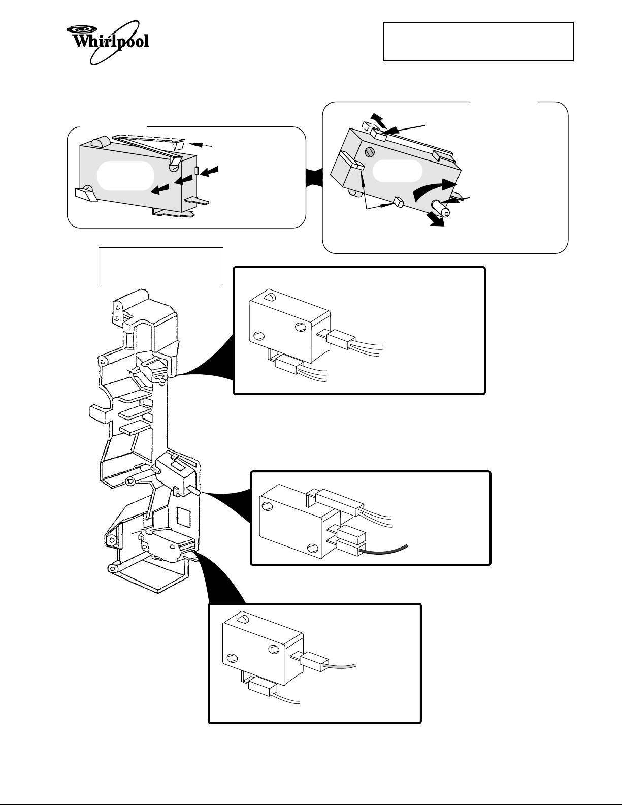
INSET 1
SECONDARY
INTERLOCK
SWITCH
INTERLOCK SWITCH
HOUSING ASSEMBLY
1.
RAISE THIS LOCKING
ARM TO RELEASE
SWITCH FROM HOUSING.
2.
PRESS BODY IN
THIS DIRECTION TO
REMOVE SWITCH
FROM HOUSING.
Cooking Products Service Manual
Original March, 1997 4322167
© 1997 Whirlpool Corporation
INSET 2
ALL OTHER
SWITCHES
NOTE: THESE POSTS
HOLD THE SWITCH IN
PLACE ON THE HOUSING
AND ARE STATIONARY.
SECONDARY INTERLOCK
SWITCH
1.
PUSH THIS LOCKING
ARM BACK TO UNLOCK
SWITCH.
2.
ROTATE SWITCH ON THIS
PIN AND REMOVE
SWITCH FROM HOUSING.
Page 2-9
WHITE (H.V. Transformer)
SMALL WHITE (Monitor Switch)
LARGE WHITE (Power Cord)
SMALL WHITE (Oven Lamp)
INTERLOCK MONITOR
PRIMARY INTERLOCK
SWITCH
SWITCH
WHITE (Turntable Motor)
WHITE (Secondary Switch)
RED (H.V. Transformer)
PINK (CN2 Pin 1)
Blue (CN2 Pin 3)
Interlock Switch Wiring
2-9
Page 20

REMOVING THE BASE THERMAL FUSE
CONTROL PANEL
OPENING
YELLOW
PINK
WHITE
BASE
THERMAL FUSE
WARNING
Personal Injury Hazard
Disconnect from the electrical supply before servicing the unit. Failure to do so
could result in death or electrical shock.
2. Remove the two screws from the top of
the cabinet for the vent grille and remove
the grille (see the illustration on page
2-3).
3. Remove the control panel from the microwave oven (see page 2-6).
4. Remove the mounting screws from the
base thermal fuse and remove it.
1. Disconnect the electrical supply to the
microwave oven.
5. Unplug the connectors from the terminals
of the base thermal fuse.
6. Install the new base thermal fuse and
reassemble the microwave oven.
THE BASE THERMAL FUSE CLOSES
AT 133˚F & RESETS @ 104˚F.
2-10
Page 21
Cooking Products Service Manual
Original March, 1997 4322167
© 1997 Whirlpool Corporation
Page 2-11
REMOVING THE MAGNETRON THERMAL FUSE
4. Unplug the line cord connector and re-
WARNING
Personal Injury Hazard
move the line cord.
5. Unplug the connector from the terminals
of the fan motor.
Disconnect from the electrical supply before servicing the unit. Failure to do so
could result in death or electrical shock.
1. Disconnect the electrical supply to the
microwave oven.
2. Remove the microwave oven from its
mounting location (see page 2-2).
3. Remove the vent grille and cabinet from
the microwave oven (see the illustration
on page 2-3).
REMOVE FIVE
AIR DUCT SCREWS
6. Remove the five screws from the air duct.
7. Lift the air duct and position it so that you
can access the magnetron thermal fuse,
then remove the mounting screw, and
unplug the connectors from its terminals.
8. Install the new magnetron thermal fuse
on the air duct, and reassemble the microwave oven.
BOTTOM
OF AIR DUCT
MAGNETRON
THERMAL FUSE
THE MAGNETRON THERMAL FUSE
OPENS AT 228˚F & RESETS @ 140˚F.
2-11
UNPLUG POWER
CORD & FAN MOTOR
BLACK & RED
WIRES
Page 22

REMOVING THE CONVECTION THERMISTOR
WARNING
Personal Injury Hazard
Disconnect from the electrical supply before servicing the unit. Failure to do so
could result in death or electrical shock.
1. Disconnect the electrical supply to the
microwave oven.
2. Remove the microwave oven from its
mounting location (see page 2-2).
3. Remove the vent grille and cabinet from
the microwave oven (see the illustration
on page 2-3).
4. Remove the five screws from the air duct
and position it so that you can access the
pulley cover underneath.
5. Remove the screws from the circulation
pulley cover and the bracket, then remove the cover and the attached brackets from the top of the oven. Do not remove the brackets from the cover.
6. Remove the screw from the convection
thermistor and remove the thermistor.
7. Cut the two white wires (not the thermistor wires) coming from the control
board next to the splice.
8. Splice the white wires onto the ends of the
new convection thermistor wires. Cover
the spliced wire ends with electrical tape
so that they cannot short to the oven.
9. Mount the new convection thermistor to
the oven and reassemble the microwave
oven.
2-12
Page 23
BRACKETS
Cooking Products Service Manual
Original March, 1997 4322167
© 1997 Whirlpool Corporation
CIRCULATION
PULLEY COVER
Page 2-13
SENSOR
COVER
PHILLIPS
SCREW
REMOVE FIVE
AIR DUCT SCREWS
WHITE WIRES
CAUTION: WHEN REPLACING THE
THERMISTOR, DO NOT CUT AND SPLICE
THE WHITE WIRES, OR AN IMPROPER
SIGNAL WILL BE SENT FROM THE THERMISTOR
TO THE MICROCOMPUTER BOARD
CONVECTION
THERMISTOR
2-13
Page 24
REMOVING THE CAVITY THERMAL FUSE
3. Remove the vent grille and cabinet from
WARNING
Personal Injury Hazard
the microwave oven (see the illustration
on page 2-3).
4. Remove the five screws from the air duct.
Disconnect from the electrical supply before servicing the unit. Failure to do so
could result in death or electrical shock.
1. Disconnect the electrical supply to the
microwave oven.
2. Remove the microwave oven from its
mounting location (see page 2-2).
THE CAVITY THERMAL
FUSE OPENS AT 230˚F
CAVITY
THERMAL
FUSE
AIR DUCT
AND RESETS AT 140˚F
5. Unplug the connectors from the terminals
of the cavity thermal fuse, then lift the left
side of the air duct, and remove the cavity
thermal fuse. NOTE: There are no mounting screws holding the cavity thermal fuse
in place.
6. Install the new cavity thermal fuse in its
mounting hole, and reassemble the microwave oven.
REMOVE FIVE
AIR DUCT SCREWS
2-14
Page 25

Cooking Products Service Manual
Original March, 1997 4322167
© 1997 Whirlpool Corporation
THE OPERATING CONTROL SYSTEM
REMOVING THE OVEN LIGHT SOCKET
4. Remove the mounting screw from the light
WARNING
Personal Injury Hazard
cover and remove the cover.
5. Remove the bulb from the oven light
socket.
Page 2-15
Disconnect from the electrical supply before servicing the unit. Failure to do so
could result in death or electrical shock.
1. Disconnect the electrical supply to the
microwave oven.
2. Remove the microwave oven from its
mounting location (see page 2-2).
3. Remove the vent grille and cabinet from
the microwave oven (see the illustration
on page 2-3).
CUT
&
SPLICE
BRACKET
SOCKET
(TWIST TO
REMOVE)
BULB
MOUNTING
POST
& SCREW
LOCKING TAB
6. Cut the wires near the old light socket
body.
7. Push the locking tab and turn the socket
and remove it from the bracket.
1
8. Remove
/2" of insulation from the cut wire
ends of the black and white wires and
then splice them to the wires of the new
socket with two wire nuts.
9. Install the new light socket and its bulb,
and reassemble the microwave oven.
AIRDUCT
2-15
Page 26

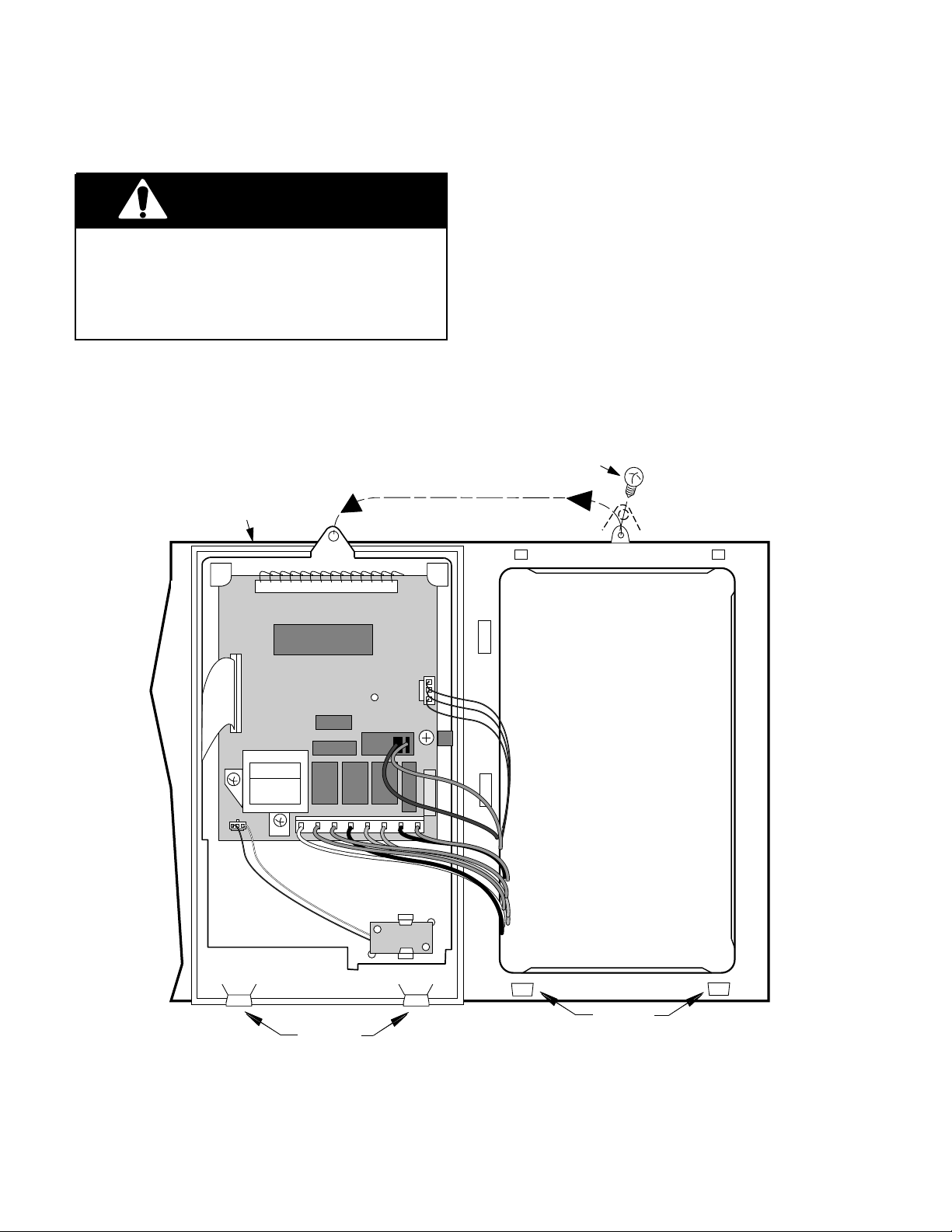
REMOVING THE CONTROL CIRCUIT BOARD
& THE TURNTABLE INDICATOR CIRCUIT BOARD
WARNING
Personal Injury Hazard
Disconnect from the electrical supply before servicing the unit. Failure to do so
could result in death or electrical shock.
1. Disconnect the electrical supply to the
microwave oven.
2. Remove the two screws from the top of
the cabinet for the vent grille and remove
the grille (see the illustration on page
2-3).
PANEL SCREW
TURN PANEL OVER
CONTROL BOARD
CONTROL
3. Remove the screw from the top center tab
of the control panel, then lift the panel so
that the bottom tabs are out of the slots
and turn it over.
To remove the control circuit board,
4.
disconnect the three harness connectors
and the ribbon cable (see the inset), and
remove the three mounting screws.
To remove the turntable indicator cir-
5.
cuit board, unplug the connector at CN5,
and unsnap it from the locking arms.
6. Install the new circuit board in its mounting location and reassemble the microwave oven.
CN5
LOCKING ARMS
TURNTABLE
INDICATOR
BOARD
MOUNTING
SCREWS
BOTTOM
TABS
DISCONNECT
THREE HARNESS
CONNECTORS
CN3
BOTTOM
SLOTS
INSERT CABLE INTO
REAR CONTACT SLOT
2-16
RIBBON CABLE
COLLAR
UNSNAP/SNAP LOCKING
ARMS ON COLLAR TO
BOTTOM SIDE OF
CONNECTOR
CONNECTOR
INSET
Page 27

REMOVING THE FAN MOTOR
WARNING
Personal Injury Hazard
Disconnect from the electrical supply before servicing the unit. Failure to do so
could result in death or electrical shock.
1. Disconnect the electrical supply to the
microwave oven.
2. Remove the microwave oven from its
mounting location (see page 2-2).
3. Remove the vent grille and cabinet from
the microwave oven (see the illustration
on page 2-3).
Cooking Products Service Manual
Original March, 1997 4322167
© 1997 Whirlpool Corporation
Page 2-17
4. Pull the fan blade and press-on washer
off the fan motor shaft.
5. Unplug the connector from the fan motor
terminals.
6. Remove the two mounting screws from
the fan motor and remove the motor from
the air duct.
7. Install the new fan motor in its mounting
location and reassemble the microwave
oven.
MOUNTING
SCREW
CONNECTOR
FAN MOTOR
AIR DUCT
FAN BLADE
PRESS-ON WASHER
2-17
Page 28

REMOVING THE POWER CORD
WARNING
3. Remove the vent grille and cabinet from
the microwave oven (see the illustration
on page 2-3).
Personal Injury Hazard
Disconnect from the electrical supply before servicing the unit. Failure to do so
could result in death or electrical shock.
1. Disconnect the electrical supply to the
microwave oven.
2. Remove the microwave oven from its
mounting location (see page 2-2).
POWER CORD
4. Unplug the connector on the old power
cord from the air duct connector and install the new power cord.
5. Reassemble the microwave oven.
POWER CORD
CONNECTOR
LOCKING
ARM
AIR DUCT
CONNECTOR
2-18
Page 29

REMOVING THE BLOWER MOTOR CAPACITOR
REMOVE FIVE
AIR DUCT SCREWS
WARNING
Personal Injury Hazard
Disconnect from the electrical supply before servicing the unit. Failure to do so
could result in death or electrical shock.
1. Disconnect the electrical supply to the
microwave oven.
WIRE NUT
CUT &
SPLICE
WIRES
Cooking Products Service Manual
Original March, 1997 4322167
© 1997 Whirlpool Corporation
Page 2-19
2. Remove the microwave oven from its
mounting location (see page 2-2).
3. Remove the vent grille and cabinet from
the microwave oven (see the illustration
on page 2-3).
4. Remove the five screws from the air duct.
5. Cut the wires near the body of the blower
motor capacitor.
1
6. Remove
/2" of insulation from the cut wire
ends of the red harness wires and then
splice them to the wires of the new capacitor with two wire nuts.
7. Install the new blower motor capacitor to
the air duct and reassemble the microwave oven.
BLOWER MOTOR
CAPACITOR
AIR DUCT
MOUNTING SCREW
2-19
Page 30

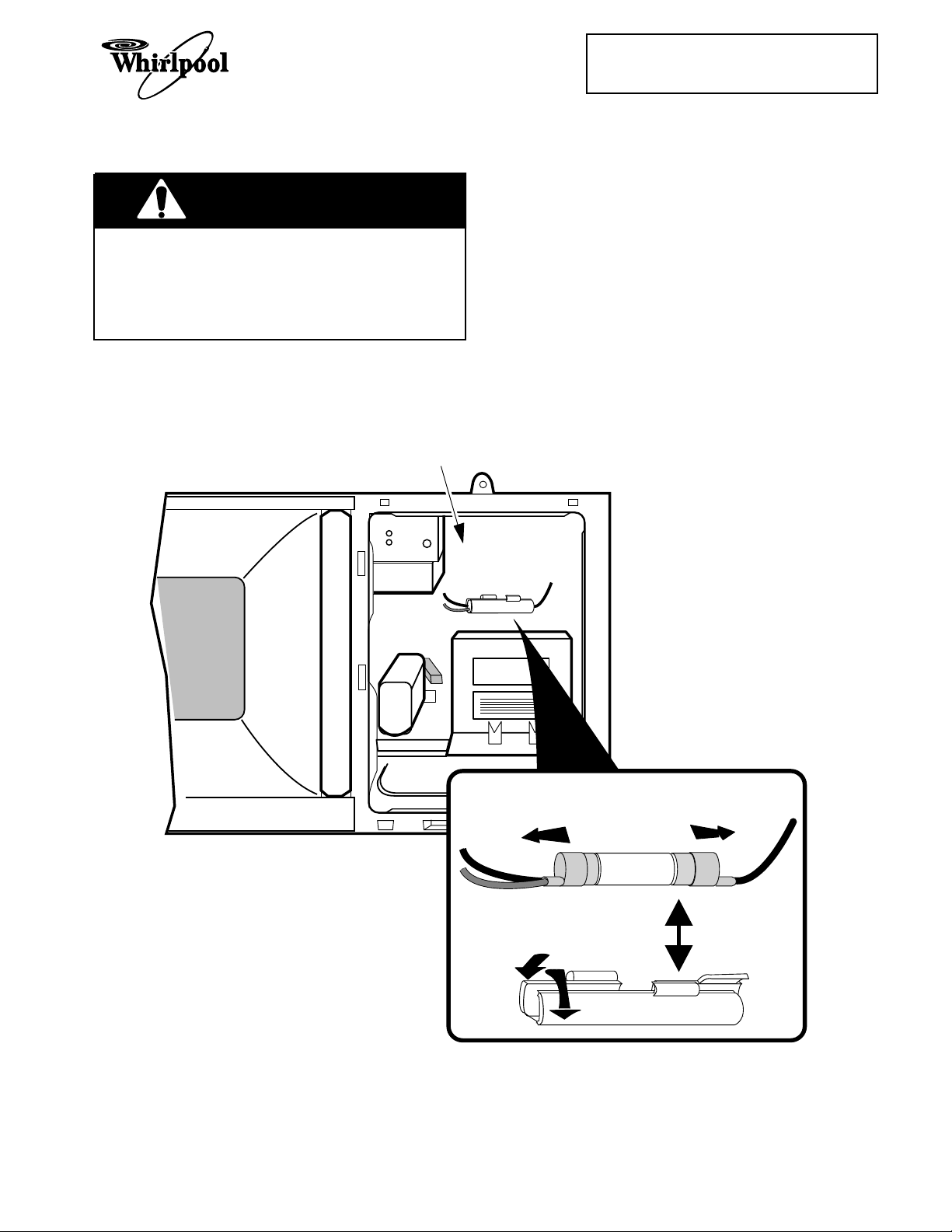
REMOVING THE CONVECTION HEATING ELEMENT
6. Remove the screw from the gas sensor
WARNING
Personal Injury Hazard
Disconnect from the electrical supply before servicing the unit. Failure to do so
could result in death or electrical shock.
1. Disconnect the electrical supply to the
microwave oven.
2. Remove the microwave oven from its
mounting location (see page 2-2).
3. Remove the vent grille and cabinet from
the microwave oven (see the illustration
on page 2-3).
4. Remove the five screws from the air duct,
then lift the duct and postion it so you can
access the convection heating element.
5. Remove the three phillips screws from
the circulation pulley cover and the one
from the bracket, and remove the cover
and attached brackets from the top of the
oven. Do not remove the brackets from
the cover.
and position the sensor out of the way.
7. Unhook the drive belt from the circulation
fan pulleys and set it aside.
8. Remove the phillips screw from the convection thermistor that is located on the
top plate. Remove the thermistor and
position it out of the way.
9. Disconnect the wires from the convection
heating element terminals.
10. Remove the phillips screws from the top
cover, remove it from the oven, and turn it
over.
11. Remove the two phillips screws from the
convection heating element bracket.
Unclip the element from the cover and
remove it.
12. Install the new heating element into the
mounting clips in the top cover, and secure the mounting bracket with two phillips
screws.
13. Reassemble the microwave oven.
2-20
Page 31

UNCLIP
ELEMENT
HERE
HEATING ELEMENT
VIEWED FROM UNDER
TOP PLATE
BRACKETS
Cooking Products Service Manual
Original March, 1997 4322167
© 1997 Whirlpool Corporation
HEATING ELEMENT
MOUNTING SCREWS
CIRCULATION
PULLEY COVER
Page 2-21
GAS SENSOR
CONVECTION
THERMISTOR
SENSOR
COVER
TOP PLATE
MOUNTING SCREWS
TOP PLATE
REMOVE FIVE
AIR DUCT SCREWS
CONVECTION
HEATING
ELEMENT
YELLOW
WIRES
2-21
Page 32

REMOVING THE GAS SENSOR
WARNING
Personal Injury Hazard
Disconnect from the electrical supply before servicing the unit. Failure to do so
could result in death or electrical shock.
1. Disconnect the electrical supply to the
microwave oven.
SENSOR
COVER
MOUNTING
SCREW
SENSOR
GAS
BOARD
WH
RD
RED
YL
WHT
YEL
2. Remove the microwave oven from its
mounting location (see page 2-2).
3. Remove the vent grille and cabinet from
the microwave oven (see the illustration
on page 2-3).
4. Remove the five screws from the air duct,
then lift the duct and postion it so you can
access the gas sensor.
5. Remove the screw from the gas sensor
board and remove it from the sensor cover,
then unplug the connector from the control board.
6. Install the new gas sensor board and then
reassemble the microwave oven.
REMOVE FIVE
AIR DUCT SCREWS
2-22
Page 33

REMOVING THE STIRRER MOTOR
REMOVE FIVE
AIR DUCT SCREWS
WARNING
Personal Injury Hazard
Disconnect from the electrical supply before servicing the unit. Failure to do so
could result in death or electrical shock.
1. Disconnect the electrical supply to the
microwave oven.
MOUNTING
SCREWS
STIRRER MOTOR
STIRRER
BLADE
COVER
CONNECTOR
TOP
TOP
Cooking Products Service Manual
Original March, 1997 4322167
© 1997 Whirlpool Corporation
Page 2-23
2. Remove the microwave oven from its
mounting location (see page 2-2).
3. Remove the vent grille and cabinet from
the microwave oven (see the illustration
on page 2-3).
4. Remove the five screws from the air duct
and lift the duct just enough to access the
stirrer motor, then unplug the connector
from the stirrer motor terminals.
5. Remove the two mounting screws from
the stirrer motor, lift the motor straight up
so that the shaft is free of the stirrer
blade, and remove the motor.
6. Install the new stirrer motor so the motor
shaft fits into the hole of the rectangular
pivot on the stirrer blade, and secure the
motor to its mounting location.
7. To access the stirrer blade, unsnap the
two fasteners from the top cover inside
the oven cavity, and lower the cover and
the stirrer blade. NOTE: When you reassemble the cover and stirrer blade, make
sure that you position the blade with the
“TOP” marking facing up.
8. Reassemble the microwave oven.
FASTENERS
2-23
Page 34

REMOVING THE TURNTABLE MOTOR
WARNING
Personal Injury Hazard
Disconnect from the electrical supply before servicing the unit. Failure to do so
could result in death or electrical shock.
1. Disconnect the electrical supply to the
microwave oven.
2. From inside the oven cavity, lift the turntable rest off the shaft of the turntable
motor
3. Remove the base plate from the microwave oven and unplug the cooktop light
connector (see the illustration on page
2-3).
4. Unplug the connector and remove the two
mounting screws from the turntable motor, then remove the motor from the bottom of the microwave oven.
5. Mount the new turntable motor and reassemble the microwave oven.
TURNTABLE REST
BOTTOM OF
OVEN
TURNTABLE
MOTOR
CONNECTOR
2-24
Page 35

REMOVING THE COOKTOP LIGHT SOCKETS
WARNING
Personal Injury Hazard
Disconnect from the electrical supply before servicing the unit. Failure to do so
could result in death or electrical shock.
1. Disconnect the electrical supply to the
microwave oven.
2. Remove the base plate from the microwave oven and unplug the cooktop light
connector (see the illustration on page
2-3).
Cooking Products Service Manual
Original March, 1997 4322167
© 1997 Whirlpool Corporation
3. Remove the bulbs from the sockets and
unplug the socket wire connector from
the microwave oven.
4. To remove the sockets, press the locking
tabs near the base of each socket, and
twist the socket until the tabs align with
the slots in the bracket, then remove the
sockets from the bracket.
5. Mount the new sockets to the bracket,
reinstall the bulbs, and reassemble the
microwave oven.
Page 2-25
TWIST SOCKET
TO REMOVE
BASE
BASE
PLATE
PLATE
CONNECTOR
COOKTOP LIGHTS
2-25
Page 36

THE HIGH VOLTAGE COMPONENTS
WARNING
ACCESSING THE COMPONENTS
The components for service in this section
include the:
Magnetron
High Voltage Rectifier
High Voltage Capacitor
High Voltage Transformer
The locations of the high voltage components
are shown below. All of the high voltage components are accessible through the front control panel cutout. However, the cabinet must
be removed to access the mounting screws for
the magnetron. Refer to the following pages
for servicing the high voltage components.
Personal Injury Hazard
Disconnect from the electrical supply before servicing the unit. Failure to do so
could result in death or electrical shock.
Discharge the high voltage capacitor before working inside the oven. Failure to do
so could result in death or electrical shock.
MAGNETRON
HIGH VOLTAGE
CAPACITOR
HIGH VOLTAGE
RECTIFIER
HIGH VOLTAGE
TRANSFORMER
2-26
Page 37

REMOVING THE MAGNETRON
WARNING
Personal Injury Hazard
Disconnect from the electrical supply before servicing the unit. Failure to do so
could result in death or electrical shock.
Cooking Products Service Manual
Original March, 1997 4322167
© 1997 Whirlpool Corporation
2. Discharge the high-voltage capacitor.
3. Remove the microwave oven from its
mounting location, then remove the vent
grille and the cabinet from the oven (see
pages 2-2 and 2-3).
4. Remove the control panel from the microwave oven (see page 2-6).
Page 2-27
1. Disconnect the electrical supply to the
microwave oven.
WARNING
Personal Injury Hazard
Disconnect from power supply before servicing. Discharge the capacitor using a
20,000-ohm discharge resistor, or an insulated plastic-handle screwdriver to short
across the capacitor terminals.
5. From inside the control panel opening,
support the magnetron with one hand,
then remove the four mounting screws
from the magnetron through the four access holes in the top of the air duct.
6. Unplug the wire connector from the back
of the magnetron and remove the magnetron from the oven.
7. Install the new magnetron and reassemble
the microwave oven.
MAGNETRON
MOUNTING
SCREWS
MAGNETRON
2-27
CONNECTOR
Page 38

REMOVING THE HIGH VOLTAGE RECTIFIER
AND THE HIGH VOLTAGE CAPACITOR
2. Discharge the high-voltage capacitor.
WARNING
Personal Injury Hazard
Disconnect from the electrical supply before servicing the unit. Failure to do so
could result in death or electrical shock.
1. Disconnect the electrical supply to the
microwave oven.
WARNING
Personal Injury Hazard
Disconnect from power supply before servicing. Discharge the capacitor using a
20,000-ohm discharge resistor, or an insulated plastic-handle screwdriver to short
across the capacitor terminals.
3. Remove the two screws from the top of
the cabinet for the vent grille and remove
the grille (see the illustration on page
2-3).
4. Remove the control panel from the microwave oven (see page 2-6).
5. From inside the control panel opening,
remove the screw from the capacitor
bracket, and remove the bracket and capacitor so that you can access the capacitor terminals.
6. Unplug the wire connectors and the high
voltage rectifier from the capacitor terminals and remove the capacitor and rectifier from the oven.
7. Install the high voltage rectifier and capacitor and reassemble the microwave
oven.
HV RECTIFIER
STRAP
MOUNTING
SCREW
2-28
ORG TO
MAGNETRON
RED TO HV
TRANSFORMER
HV RECTIFIER
Page 39

Cooking Products Service Manual
WARNING
Original March, 1997 4322167
© 1997 Whirlpool Corporation
Page 2-29
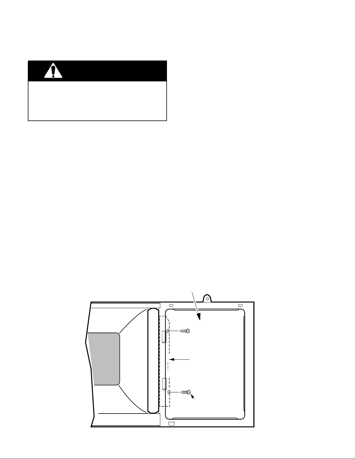
REMOVING THE HIGH VOLTAGE TRANSFORMER
WARNING
Personal Injury Hazard
Disconnect from the electrical supply before servicing the unit. Failure to do so
could result in death or electrical shock.
1. Disconnect the electrical supply to the
microwave oven.
Personal Injury Hazard
Disconnect from power supply before servicing. Discharge the capacitor using a
20,000-ohm discharge resistor, or an insulated plastic-handle screwdriver to short
across the capacitor terminals.
2. Discharge the high-voltage capacitor.
3. Remove the two screws from the top of
the cabinet for the vent grille and remove
the grille (see the illustration on page
2-3).
4. Remove the control panel from the microwave oven (see page 2-6).
5. Disconnect the filament wires from the
magnetron, then disconnect the three remaining wires from the terminals at the
front and back of the high voltage transformer.
6. Remove the three hex nuts from the high
voltage transformer and remove the transformer from the oven.
ORG TO
HV CAP
RED & WHITE
PRIMARY WIRES
7. Install the new high voltage transformer
and reassemble the microwave oven.
FILAMENT TO
MAGNETRON
HV TRANSFORMER
HEX NUTS
2-29
Page 40

— NOTES —
2-30
Page 41

Cooking Products Service Manual
Original March, 1997 4322167
© 1997 Whirlpool Corporation
Page 3-1
COMPONENT DESCRIPTION & TESTING
IMPORTANT SAFETY INSTRUCTIONS
CAUTION
Warning To Service Technicians!
To avoid possible exposure to microwave radiation or energy, visually check the oven for damage to the
door and door seal before operating any oven. Use a microwave survey meter to check the amount of
leakage before servicing. In the event the R.F. Ieakage exceeds 4 mW/cm at 5 cm, appropriate repair must
be made before continuing to service the unit. Check interlock function by operating the door latch. The
oven cook cycle should cut off before the door can be opened.
The door and latching assembly contains the radio frequency energy within the oven. The door is protected
by three safety interlock switches. Do not attempt to defeat them.
UNDER NO CIRCUMSTANCES SHOULD YOU TRY TO OPERATE THE OVEN WITH THE DOOR OPEN.
• Proper operation of microwave ovens requires that the magnetron be properly assembled to the
waveguide and cavity. Never operate the magnetron unless it is properly installed.
• Be sure the “RF” seal is not damaged and is assembled around the magnetron dome properly when
installing the magnetron.
• Routine service safety procedures should be exercised at all times.
• Untrained personnel should not attempt service without a thorough review of test procedures and safety
information contained in this manual.
PRECAUTIONS TO BE OBSERVED BEFORE AND
DURING SERVICING TO AVOID POSSIBLE EXPOSURE
TO EXCESSIVE MICROWAVE ENERGY
A. Do not operate or allow the oven to be operated with the door open.
B. Make the following safety checks on all ovens to be serviced before activating the magnetron or other
microwave source and make repairs as necessary.
1. Interlock Operation
2. Proper Door Closing
3. Seal and Sealing Surfaces (Arcing, Wear and Other Damage)
4. Damage to or Loosening of Hinges and Latches
5. Evidence of Dropping or Abuse
C. Before turning on the microwave power for any service test or inspection within the microwave
generating components, check the magnetron, wave guide or transmission line and cavity for proper
alignment.
D. Any defective or misadjusted components in the interlock, monitor, door seal and microwave
generation and transmission system shall be repaired or adjusted by procedures described in the
Basic Service Manuals for the specific microwave oven being serviced before the oven is released
to the owner.
E. A microwave leakage check to verify compliance with Federal Performance Standards should be
performed on each oven prior to release to the owner.
F. Do not attempt to operate the oven if the door glass is broken.
3-1
Page 42

Whirlpool microwave ovens have a monitoring system designed to assure proper operation of the safety
interlock systems.
The interlock monitor switch will immediately cause the oven fuse to blow if the door is opened and the
primary door interlock switch and/or the secondary interlock switch contacts fail in a closed position.
CAUTION: REPLACE BLOWN FUSE WITH 15 AMPERE CLASS H FUSE ONLY.
Test the upper and lower door interlock switches, cook relay and interlock monitor switch (middle switch)
for proper operation as described in the component test procedures, before replacing the blown oven fuse.
DO NOT ATTEMPT TO REPAIR STICKING CONTACTS OF ANY INTERLOCK SWITCH, SAFETY
SWITCH OR COOK (LATCH) RELAY. REPLACE THE SWITCHES AND RELAY.
Any indication of sticking contacts during component tests requires replacement of that component to
assure reliability of the safety interlock system.
IF THE FUSE IS BLOWN, THE MONITOR, PRIMARY AND SECONDARY INTERLOCK SWITCHES MUST
BE REPLACED. BE SURE THEY ARE PROPERLY CONNECTED.
Precautions to Avoid Possible Exposure
to Excessive Microwave Energy
DO NOT attempt to operate the oven with the door open since open-door operation can result
in harmful exposure to microwave energy. It is important not to defeat or tamper with the safety
interlocks.
DO NOT place any object between the oven front face and the door or allow soil or cleaner
residue to accumulate on sealing surfaces.
DO NOT operate the oven if it is damaged. It is particularly important that the oven door close
properly and that there is no damage to the:
1. Door (bent).
2. Hinges and Latches (broken or loosened).
3. Door Seals and Sealing Surfaces.
DO NOT operate the microwave oven if the door window is broken.
The microwave oven should be checked for microwave leakage by qualified service personnel
after a repair is made.
The oven should not be adjusted or repaired by anyone except properly qualified service
personnel.
DO NOT operate the microwave oven with the outer cabinet removed.
3-2
Page 43

Cooking Products Service Manual
Original March, 1997 4322167
© 1997 Whirlpool Corporation
Page 3-3
CAUTION
• High voltages are present during the cook
cycle. Extreme caution should be observed
at all times.
• Abrasive cleansers, steel-wool pads, gritty
wash cloths, etc. can damage the control panel
and the interior and exterior oven surfaces. Use
a sponge with mild detergent or paper towels
with spray glass cleaner. Apply spray glass
cleaner to paper towel. Do not spray directly
on oven.
• Before touching any oven component or wiring, always unplug the oven from its power
source and discharge the capacitor by using a
20,000 ohm discharge resistor or use an insulated plastic handle screwdriver to short across
the capacitor terminals.
• Check that the unit is grounded before troubleshooting. Be careful of the high voltage circuits.
Discharge any static charge from your body by
touching ground before handling any part of the
circuitry on the control board. Electrostatic discharge may damage the control circuit.
• Do not touch oven components or wiring during operation. Attach meter leads with alligator
clips when making operational tests.
• For continued protection against radiation emission, replace only with these types of switches:
Primary (Interlock) Switch: SZM-V16-FA-63 or
VP-533A-OF; Secondary (Interlock) Switch:
SZM-V01-FA-32; Interlock (Monitor) Switch:
SZM-Vl6-FA-62 or VP-532A-OF; Oven Lamp
Switch: SZM-V6-FA-31 or VP-331A-OD.
• It is neither necessary nor advisable to attempt
measurement of high voltage.
WARNING
• Disconnect the oven from electrical supply before servicing. Failure to do so could result in
electrical shock or death.
• Improper use of the grounding plug can result
in a risk of electrical shock. Do not, under any
circumstance, cut or remove the third ground
prong from the power cord plug.
Fire, Electrical Shock, Excessive
Exposure to Microwave Energy,
Personal Injury & Product
Damage Hazard
• Do not block the rear air intake openings or
exhaust vents. Allow a few inches of space at
the back of the oven where intake openings
and exhaust vents are located. Blocking the air
intake openings and exhaust vents can cause
damage to the oven and poor cooking results.
Make sure the microwave oven legs are in
place to ensure proper airflow.
• Do not install the oven next to or over a heat
source (a cooktop or range).
• Do not install oven in any area where excessive heat and steam are generated. This could
cause fire, electrical shock, excessive exposure
to microwave energy, other personal injury or
damage to the outside of the cabinet.
• Attaching the adaptor ground terminal to the
wall receptacle cover screw does not ground
the appliance unless the cover screw is metal
and not insulated and the wall receptacle is
grounded through the house wiring.
3-3
Page 44

THE THERMAL FUSES
There are three thermal fuses in the OTR
Microwave Oven. They are: the magnetron
thermal fuse, the cavity thermal fuse, and the
base thermal fuse. The magnetron and cavity
The base thermal fuse is located directly behind the control panel. It is a normally-open
fuse that, when closed, activates the blower
motor at a low speed.
thermal fuses are located inside the highvoltage section of the oven. These two thermal fuses are normally-closed, and will open
POSSIBLE CUSTOMER COMPLAINT:
The unit turns on by itself.
at a set temperature to disable the oven. Both
of these fuses are resettable.
Magnetron Thermal Fuse Opens @ 228˚F/109˚C Resets @ 140˚F/60˚C
Cavity Thermal Fuse Opens @ 230˚F/110˚C Resets @ 140˚F/60˚C
Base Thermal Fuse Closes @ 133˚F/56˚C Resets @ 104˚F/40˚C
MAGNETRON
CAVITY
THERMAL
FUSE
THERMAL FUSE
3-4
BASE
THERMAL FUSE
Page 45

Cooking Products Service Manual
Original March, 1997 4322167
© 1997 Whirlpool Corporation
THE BLOWER MOTOR CAPACITOR
Page 3-5
The blower motor capacitor is located below
the air duct at the indicated location. It is in
use any time the blower (vent) motor is oper-
AIR DUCT
BLOWER MOTOR
CAPACITOR
ating. The capacitor helps to maintain a constant voltage to the blower motor so that it
runs more efficiently.
TESTING
1. Set the ohmmeter to the
R x 10K
scale.
2. Measure across the capacitor terminals.
The ohmmeter should indicate several
ohms, then gradually return to infinity.
3-5
Page 46

THE GAS SENSOR
The gas sensor is used during the “Sensor
Cook” operation of the oven. It is located
above the oven and is mounted on the left side
of the sensor cover. The sensor consists of
two circuits housed on a small microcomputer
board that is supplied with a current to keep it
heated. The sensor heat conductivity will vary,
depending upon the humidity of the oven.
Changing humidity conditions, due to the cook-
ing process within the oven cavity, causes a
difference in potential between these two cir-
cuits. This difference is monitored by the mi-
crocomputer during cooking, allowing the mi-
crocomputer to determine the proper cook
time.
NOTE: Always verify that the sensor cover is
not obstructed (proper air flow is passing over
the sensor), and that the fan motor is working
properly, before replacing the gas sensor.
TESTING
SENSOR
COVER
MOUNTING
SCREW
SENSOR
GAS
BOARD
1. Set the ohmmeter to the
R x 1
scale.
2. Remove the 3-pin connector from
the control circuit board and measure the resistance between the:
a)Red & white wire terminals.
You should measure 20 Ω @
WH
RD
RED
YL
WHT
YEL
68˚F.
b)White & yellow wire terminals.
You should measure infinity.
3-6
Page 47

THE CONVECTION THERMISTOR
The convection thermistor is located under
the circulation pulley cover and is used during
the convection operation of the oven. When
the temperature increases, the resistance of
the thermistor decreases. The thermistor resistance is monitored by the microcomputer.
As the oven temperature rises and falls, the
TESTING
Cooking Products Service Manual
Original March, 1997 4322167
© 1997 Whirlpool Corporation
Page 3-7
thermistor signal going back to the microcomputer causes the heater relay to open and
close, and cycles the heating element on and
off.
NOTE: Verify that the heating element is working correctly before replacing a thermistor.
1. Set the ohmmeter to the
R x 10K
scale.
2. Remove the 6-pin connector from
the control circuit board and measure across terminals 5 & 6.
You should measure 155 kΩ to
350 kΩ @ 68˚F.
BRACKETS
PHILLIPS
SENSOR
COVER
SCREW
CIRCULATION
PULLEY COVER
CONVECTION
THERMISTOR
3-7
Page 48

THE CONVECTION HEATING ELEMENT
The 1400-watt convection heating element is
located under the circulation pulley cover and
the top plate. The heating element heats the
air that is distributed into the oven cavity by
the convection fan. It operates on 120 VAC
and is controlled by the convection thermistor,
UNCLIP
ELEMENT
HERE
HEATING ELEMENT
VIEWED FROM UNDER
TOP PLATE
BRACKETS
and the heater relay on the microcomputer
board. During a convection, or combination
cooking cycle, the heater cycles on and off to
maintain the programmed cavity temperature.
The heating element surrounds the convection fan blade and is not visible through the
oven cavity.
HEATING ELEMENT
MOUNTING SCREWS
CIRCULATION
PULLEY COVER
CONVECTION
THERMISTOR
SENSOR
COVER
TESTING
1. Set the ohmmeter to the
R x 1
scale.
2. Measure across the heating element terminals.
You should measure between
40 Ω and 90 Ω @ 68˚F.
TOP PLATE
CONVECTION
HEATING
ELEMENT
YELLOW
WIRES
3-8
Page 49

MOTORS
Cooking Products Service Manual
Original March, 1997 4322167
© 1997 Whirlpool Corporation
Page 3-9
Blower Motor
—Removes smoke and odors from the kitchen
cooking area through outside venting or recirculation.
Fan Motor
—Cools the magnetron and circulates air through the
oven during microwave cooking.
Stirrer and Turntable Motors
—Distribute microwave energy
evenly during microwave cooking.
STIRRER MOTOR
TURNTABLE
MOTOR
BLOWER MOTOR
FAN MOTOR
3-9
Page 50

PROGRAMMING CHECKS
TOUCH PANEL CONTINUITY TEST
1. Unplug the microwave oven’s power sup-
ply cord.
2. Open the oven door.
3. Plug the power cord back into the AC
receptical. You should see the following
display if any of the interlock switches are
closed:
– f 2 –
If the sensor is defective, or if the wires are not
properly connected, you will see the following
display:
– f 1 –
3-10
Page 51

CHARTS
Cooking Products Service Manual
Original March, 1997 4322167
© 1997 Whirlpool Corporation
Page 3-11
PROBLEM POSSIBLE CAUSE
Line fuse blows when power
cord is plugged into a wall
receptacle.
Oven will not operate.
Shorted wire in power cord,
wiring harness, or overload
circuit.
1. No power at wall plug. 1. Check fuse or breaker
2. Open wire in power cord
or wiring harness.
3. Control board.
4. Line fuse.
5. Thermal fuses.
Oven cavity light will not turn
on.
1. Bulb is burned out.
2. Lamp socket.
3. Oven lamp switch.
4. Open wiring between the
above components.
5. Control board.
TEST PROCEDURE
OR CORRECTION
1. Check wiring with ohmmeter for continuity.
2. Use separate 15- to 20ampere circuit.
box.
2. Check wiring with ohmmeter for continuity.
3. Check board.
4. Check fuse.
5. Check fuses.
1. Replace bulb.
2. Check lamp socket.
3. Check control board.
4. Repair open wire.
5. Check control board.
Oven will not go into “Cook”
cycle when the door is closed.
Oven goes into “Cook” cycle,
but does not complete the
cycle. Heat is produced in the
oven load.
1. Control board.
2. Line fuse and/or thermal
fuses.
3. Interlock switches.
4. Open wiring between the
above components.
1. Control board.
2. Low line voltage (should
be at least 108-volts
AC).
3. Thermal fuse.
4. Thermal fuse on magnetron.
5. Circuit is overloaded.
1. Check control board.
2. Check line fuse and/or
thermal fuses.
3. Check interlockswitches.
4. Repair open wire.
1. Check control board.
2. Use separate 15- to 20ampere circuit.
3. Check thermal fuse.
4. Check thermal fuse on
magnetron.
5. Use separate 15- to 20ampere circuit.
3-11
Page 52

PROBLEM
POSSIBLE CAUSE
TEST PROCEDURE
OR CORRECTION
Little or no heat is produced
in the oven load.
Oven fuse blows when the
door is opened.
Oven lamp goes on with the
door open, but the light goes
out when the door is closed
with the control on.
The power source fuse blows
when the door starts to open.
1. High voltage transformer.
2. Rectifier diode.
3. High voltage capacitor.
4. Magnetron.
5. Power selector.
1. Primary interlock switch. 1. Check primary interlock
2. Shorted wire harness.
1. Secondary interlock. 1. Check secondary inter-
1. High voltage transformer.
2. Secondary circuit of the
high voltage transformer
is shorted.
3. High voltage capacitor is
shorted.
4. Shorted wiring between
the above components.
1. Check the high voltage
transformer.
2. Check the high voltage
rectifier diode.
3. Check the high voltage
capacitor.
4. Check the magnetron.
5. Check the power selector.
switch.
2. Repair wiring.
lock.
1. Check the high voltage
transformer.
2. Check the high voltage
transformer.
3. Check the high voltage
capacitor.
4. Use an ohmmeter to
check continuity, and
repair wiring.
5. Check blower motor.5. Blower motor.
Fan motor will not operate. 1. Check fan motor.
1. Fan motor.
2. Open or loose wiring in
circuit to fan motor.
3-12
2. Use ohmmeter to check
continuity, and repair
wiring.
Page 53

Cooking Products Service Manual
Original March, 1997 4322167
© 1997 Whirlpool Corporation
Page 3-13
PROBLEM
Blower motor will not operate.
POSSIBLE CAUSE
1. Blower motor.
2. Control board.
3. Open or loose wiring in
circuit to blower motor.
Cooktop lamps do not come
on.
1. Bulb burned out.
2. Control board.
3. Lamp sockets.
4. Open wiring between the
above components.
Oven heats too fast. 1. Line voltage is too high
(should be between 108and 132-volts AC).
2. Control board.
TEST PROCEDURE
OR CORRECTION
1. Check blower motor.
2. Check control board.
3. Use ohmmeter to check
continuity, and repair
wiring.
1. Check bulb.
2. Check control board.
3. Check lamp sockets.
4. Use ohmmeter to check
continuity, and repair
wiring.
1. Use separate 15- to 20ampere circuit.
2. Check control board.
Oven cooks too slowly.
Speaker does not sound at
conclusion of cooking sequences, or after elapsed time
in Minute Timer.
Oven cooks on “HIGH” when
a lower cook power is selected.
Oven runs but will not cook.
1. Line voltage is too low
(should be between 108and 132-volts AC).
2. User error.
3. Magnetron.
1. Open connection or
failed speaker.
2. Tones are programmed
out.
1. Shorted relay.
2. Control board.
1. Secondary interlock
switch.
2. Relay 2 is open.
3. High voltage components.
1. Use separate 15- to 20ampere circuit.
2. Instruct user regarding
proper cooking times.
3. Check magnetron.
1. Replace board.
2. Program tones back in.
(Touch and hold key #1
for 4-seconds).
1. Check the control board.
2. Check control board.
1. Check secondary interlock switch.
2. Check control board.
3. Check high voltage components.
3-13
Page 54

PROBLEM
POSSIBLE CAUSE
TEST PROCEDURE
OR CORRECTION
Console will not display data,
or has incorrect data.
Erratic console display during operation.
Display continues to count
down when door is open during a “Cook” cycle.
1. No power at wall plug.
2. Open line fuse.
3. Thermal fuse.
4. Thermal fuse on magnetron.
5. Interlock safety switches.
6. Control board.
1. Magnetron. 1. Check magnetron.
1. Secondary interlock
switch.
2. Control board.
1. Check fuse or breaker
box.
2. Replace line fuse.
3. Check thermal fuse.
4. Check magnetron thermal fuse.
5. Check interlock safety
switches. Replace, if defective.
6. Check control board.
1. Check secondary interlock switch. Replace, if
defective.
2. Check control board.
Oven operates without a
“Start” command.
1. Defective control board.
CHECKING THE MICROWAVE POWER OUTPUT
Use the following procedure to checkout the
operation of the microwave oven.
1. Fill a 1-cup (260 ml) glass measuring cup
with warm water (between 90˚F/32˚C and
100˚F/38˚C).
2. Open the oven door, place the container
of water into the oven, and close the door.
3. Press the COOK keypad, and set the
cooking time for 4-minutes.
1. Replace control board.
4. Press the START/ENTER keypad. The
oven cavity light should come on, the
cooking cycle should begin, and the timer
should count down in “seconds” from 4:00.
1
5. After approximately 2the water should start to boil. If more than
3-minutes is required, it could mean that
the operating voltage is low, (below 110volts), or it is not functioning properly and
may need to be checked by a qualified
technician.
/2 to 3-minutes,
3-14
Page 55

Cooking Products Service Manual
Original March, 1997 4322167
© 1997 Whirlpool Corporation
CHECKING FOR MICROWAVE ENERGY LEAKAGE
When checking for R.F. Ieakage, use an ap-
CAUTION
On every service call, checks for microwave
energy emission must be made according to
the following manner.
1. Remove the cooking rack from the oven
cavity, if the microwave oven is so
equipped.
2. Place a 275 ML (9. oz.) glass of water in
the center of the oven bottom.
3. Select “HlGH” cook power, turn the microwave oven on, and test for R.F. Ieakage
using the following pattern:
a)Check around the cabinet at the front.
b)Check around the door.
c) Check across the console panel.
d)Check horizontally across the door
e)Check vertically across the door.
f) Check diagonally across the door.
g)Check across the air vents.
h)Check across the rear air vent.
NOTE: The scan speed is one-inch-per-second.
proved R.F. measuring device to assure less
than 4 mw/cm
a maximum scan rate of 2.5 cm/second, in
compliance with U.S. Government Department
of Health, Education and Welfare 21 CFR1030,
performance Standard for Microwave Ovens.
A properly operating door and seal assembly
will normally register small emissions, but they
must be no greater than 4 mw/cm
measurement uncertainty.
NOTE: Enter leakage readings in the space
BEFORE and AFTER on the service document.
All microwave ovens exceeding the emission
level of 4 mw/cm
Service for microwave ovens immediately and
the owner should be told not to use the microwave oven until it has been repaired completely.
If a microwave oven is found to operate with
the door open, report to Dept. of Service, the
manufacturer, and CDRH* immediately. Also
tell the owner not to use the oven.
The interlock monitor switch acts as the final
safety switch protecting the customer from
microwave radiation. If the interlock monitor
switch operates and opens the line fuse, the
interlock switches have failed, and you must
replace all of them (primary and secondary
interlock switches, and the monitor switch),
because their contacts may be melted and
welded together.
2
emission at 5 cm distance with
2
must be reported to Dept. of
Page 3-15
2
to allow for
EQUIPMENT
• Electromagnetic energy leakage monitor
(NARDA 8100B, HOLADAY H1501).
• 6100 cc glass beaker.
• Glass thermometer 100˚C or 212˚F.
All repairs must be performed so that microwave energy emissions are minimal.
* CDRH: Center for Device and Radiological health, food, and
drug administration.
3-15
Page 56

MAKING THE MEASUREMENTS
Measuring The Oven With The
Cabinet Installed
MEASUREMENT NOTES:
• When measuring for leakage, use the 2
(5 cm ) spacer that is provided with the
probe.
• Leakage with the outer panels removed
should be less than 5 mW/cm.sq
• Leakage for a fully assembled oven (before
the lamp switch primary is interrupted) with
the door opened slightly, should be less
2 mW/cm.sq
than
• Do not exceed the meter’s full-scale deflection.
• Do not move the test probe along the measuring surfaces faster than 1-inch-per-second (2.5 cm/sec), otherwise a false reading
will occur.
• When testing near a corner of the door,
keep the probe perpendicular to the surface, and move it horizontally without touching the surfaces, otherwise a false reading
will occur.
• Hold the test probe by its gripping surface
only, otherwise a false reading will occur.
.
.
To measure for oven leakage:
1. Pour 275 (±25cc) of water into a 600 cc
graduated beaker.
2. Place the beaker into the center of the
microwave oven.
"
3. Set the energy leakage monitor to 2,450
MHz, and use it according to the
manufacturer’s recommended test procedure to obtain the correct results.
4. Measure the microwave radiation with an
electromagnetic radiation monitor. Hold
the probe perpendicular to the surface
being measured, and measure around
the door viewing window, the exhaust
opening, and air inlet openings.
5. Operate the oven at its maximum energy
output, and take the measurements.
Measuring The Oven With The
Cabinet Removed
When the magnetron has been replaced, use
the previous procedure, and measure for microwave energy leakage after all of the necessary components are replaced or adjusted,
before the cabinet is installed. Take spe-
and
cial care to measure around the magnetron
and the waveguide.
WARNING:
not to contact any of the high voltage components when making measurements with
the cabinet removed.
Be careful
3-16
Page 57

Cooking Products Service Manual
Original March, 1997 4322167
© 1997 Whirlpool Corporation
Page 3-17
MEASURING MICROWAVE
POWER OUTPUT USING THE
IEC-705 RATING STANDARD
When determining the microwave oven’s power
output using the IEC-705 rating standard, the
following conditions must be met:
• When making microwave power output measurements, the oven is supplied with its
rated line voltage, and operated at its maximum power output setting with a load of
1000 (±5) cc of potable water.
• The water is contained in a cylindrical borosilicate glass vessel having a maximum
material thickness of
diameter of approximately 7.6
• The oven and the empty vessel are at ambient temperature prior to the start of the test.
• The initial temperature of the water is 10˚C
±2˚ (50˚F). It is measured immediately be-
fore the water is added to the vessel. After
addition of the water to the vessel, the load
is immediately placed on the center of the
shelf, which is in the lowest position, and
the microwave power switched on.
1
/8" and an outside
"
.
• The time (in seconds) for the temperature of
the water to rise by a value of 10˚C ±2˚ is
measured. The initial and final water temperatures are selected so that the maximum
difference between the final water temperature, and the ambient temperature, is 5˚C.
• The microwave power output (in watts) is
calculated, using the following formula:
(L) 4187 (∆T)
P =
T1
L = time (in seconds).
P = microwave output power.
(∆ T) = temperature rise.
• Microwave power output is measured with
the oven operating at full power. The magnetron filament heat-up time (approximately
2-seconds) is not included.
• The water is stirred to equalize the temperature throughout the vessel, prior to measuring the final water temperature.
• Stirring devices and measuring instruments
are selected to minimize the addition or
removal of heat.
3-17
Page 58

COMPONENT TESTING
FILAMENT WINDING
WARNING
ELECTRICAL SHOCK HAZARD
DISCONNECT THE POWER SUPPLY CORD
FROM THE WALL OUTLET WHEN REMOVING
THE CABINET FROM THE OVEN. PROCEED
WITH THE TESTS ONLY AFTER DISCHARGING THE HIGH VOLTAGE CAPACITOR, AND
REMOVING THE WIRE LEADS FROM THE
PRIMARY WINDING OF THE HIGH VOLTAGE
TRANSFORMER.
TEST CHARTS
TEST PROCEDURE RESULTCOMPONENT
High-Voltage Transformer (with
wire leads unplugged).
1. Set the ohmmeter to the
R x 1
the:
a) Primary winding.
b) Secondary to ground.
c) Filament winding.
SECONDARY
WINDING
scale, and measure
HIGH VOLTAGE
TRANSFORMER
PRIMARY WINDING
a) 0.3 to 0.5 ohms.
b) 65 to 120 ohms.
c) 0.2 to 0.4 ohms
Magnetron (with wire leads unplugged). NOTE: A microwave
energy leakage test must always
be performed when the oven is
serviced for any reason.
NOTE: Replace the magnetron
if the checks and all of the high
voltage component tests are
good, but the unit still does not
heat a load.
2. Set the ohmmeter to its
R x 1000
sure the:
a) Primary to ground.
b) Filament to ground.
1. Set the ohmmeter to the
R x 1
the:
a) Filament terminal.
2. Set the ommeter to the
R x 1000
sure the:
a) Filament winding to
chassis.
scale, and mea-
scale, and measure
scale and mea-
a) Normal = infinity.
b) Normal = infinity.
a) Normal readings - Less
than 1 ohm.
a) Normal = infinity.
3-18
Page 59

Cooking Products Service Manual
Original March, 1997 4322167
© 1997 Whirlpool Corporation
Page 3-19
TEST PROCEDURE RESULTCOMPONENT
High-Voltage Capacitor a) Normal - The meter indi-
Terminal-To-Terminal
Set the ohmmeter to the
R x 10 k
scale, and measure the resistance
across the capacitor terminals.
cates several ohms, then
gradually returns to infinity.
b) Abnormal - The meter
indicates infinity, or zero
CAPACITOR
ohms (a short) immediately.
Blower Motor Capacitor
Terminal-To-Case
Set the ohmmeter to the
R x 1
scale, and measure the resistance
between each terminal and the
case.
Terminal-To-Terminal
Set the ohmmeter to the
R x 10 k
scale, and measure the resistance
across the capacitor terminals.
a) Normal - The meter indi-
cates infinity.
b) Abnormal - The meter
indicates zero ohms, or
a short.
a) Normal - The meter indi-
cates several ohms, then
gradually returns to infinity.
b) Abnormal - The meter
indicates infinity, or zero
ohms (a short) immediately.
High-Voltage Rectifier
RECTIFIER
DIODE
ANODE
CATHODE
Forward Continuity
Set the ohmmeter to the
R x 1
scale, and measure the forward
resistance across the rectifier terminals with the (+) lead touching
the anode and the (–) lead touching the cathode.
Reverse Continuity
Set the ohmmeter to its highest
scale, and measure the reverse
resistance across the rectifier terminals with the (+) lead touching
the cathode and the (–) lead touching the anode.
a) Normal - The meter indi-
cates several ohms.
b) Abnormal - The meter
indicates infinity, or zero
ohms (a short).
a) Normal - The meter indi-
cates infinity.
b) Abnormal - The meter
indicates infinity, or zero
ohms (a short).
3-19
Page 60

TEST PROCEDURE RESULTCOMPONENT
Switches (with wire leads removed). All of the switches are
measured in the same manner.
N.C. CONTACTS
C.
N.O. CONTACTS
Temperature Probe
N.O. and C Terminals
Set the ohmmeter to the
scale, and measure the resistance
between the normally-open (N.O.)
and the common (C) terminals of
the switch.
N.C. and C Terminals
Set the ohmmeter to the
scale, and measure the resistance
between the normally-closed
(N.C.) and the common (C) terminals of the switch.
Set the ohmmeter to the
scale, and measure the temperature probe with the leads positioned at either terminal.
R x 1
R x 1
R x 10 k
a) Normal - The meter indi-
cates infinity.
b) Abnormal - The meter
indicates zero ohms (a
short).
a) Normal - The meter indi-
cates continuity, or zero
ohms.
b) Abnormal - The meter
indicates infinity.
Ambient Resistance
Temp. (˚F) Value
60 75.24 kΩ (±11 kΩ)
68 62.57 kΩ (±8 kΩ)
70 59.79 kΩ (±8 kΩ)
80 45.80 kΩ (±7 kΩ)
90 36.94 kΩ (±6 kΩ)
Fan Motor (with leads disconnected).
Blower Motor (with leads disconnected)
Stirrer & Turntable Motors (with
leads disconnected)
Set the ohmmeter to the
scale, and measure across the
terminals.
Set the ohmmeter to the
scale, and measure the:
a) High speed windings (blue
and black wires).
b) Low speed windings (blue
and white wires).
Set the ohmmeter to the
scale, and measure the resistance
between the motor terminals.
R x 1
R x 1
R x 1
a) Fan Motor - Normal = 130
to 155 ohms.
a) Normal - High speed: 25
to 45 ohms.
b) Normal - Low speed: 45
to 65 ohms.
a) Normal - 1 to 4 ohms.
b) Abnormal - Infinite or
zero ohms.
3-20
Page 61

Cooking Products Service Manual
Original March, 1997 4322167
© 1997 Whirlpool Corporation
Page 3-21
TEST PROCEDURE RESULTCOMPONENT
Convection Thermistor
Convection Heating Element
(with leads disconnected)
Gas Sensor
Set the ohmmeter to the
R x 10 K
scale.
Remove the 6-pin connector from
the circuit board and measure
across terminals 5 & 6.
Set the ohmmeter to the
R x 1
scale, and measure across the
terminals.
Set the ohmmeter to the
R x 1
scale.
Remove the 3-pin connector from
the circuit board and measure the
resistance between:
a) Red & white wire terminals.
b) White & yellow wire terminals.
a) Normal = 155 K to 350 K
ohms @ 68˚F.
b) Abnormal = Infinity, or
zero ohms (a short).
a) Normal = 9 to 40 ohms @
68˚F ± 2˚.
b) Abnormal = Infinity, or
zero ohms (a short).
a) 20 ohms @ 68˚F ±2˚.
b) Infinite.
3-21
Page 62

TEST PROCEDURE RESULTCOMPONENT
Touch Keyboard (see below). Measure the resistance between
the terminal pins of the keypad
(shown below) that you wish to
FPC CONNECTOR
(TOP)
check.
For example: To measure the
1
“CLOCK” keypad, refer to the il-
2
lustration, and:
3
4
1.Find the first terminal number
5
6
7
8
9
10
11
12
13
along the top bar (pin 5).
2.Find the second terminal number in the side bar (pin 8).
3.Set the ohmmeter to the
scale.
a) Touch the ohmmeter leads
R x 1
between pins 5 and 8 on the
ends of the FPC connector.
b) Press the CLOCK keypad.
Normal Reading:
100 Ω resistance.
8
9
TURNTABLE
10
11
12
FROZEN
ENTREE
KEYBOARD MATRIX
1
LIGHT
FAN
2
BEVERAGE
POPCORN
BAKED
POTATO
REHEAT
VEGETABLE
3
DEFROST
WARM
HOLD
COOK
45
CLOCK
TIMER
SET
TIMER
OFF
ADD
MINUTE
COOK
TIME
COOK
POWER
CANCEL
START
ENTER
6
60
71
82
93
OFF
7
4
5
13
3-22
Page 63

Cooking Products Service Manual
Original March, 1997 4322167
© 1997 Whirlpool Corporation
Page 3-23
TEST PROCEDURE RESULTCOMPONENT
Relay 2 (RY2)
WARNING: When you apply
power to the unit, be careful
not to touch any of the high
voltage circuits.
Set the ohmmeter to the
R x 1
scale, and check for continuity
between the two relay terminal
pins. Use the following steps.
1.Remove the wire connectors
from the relay terminals.
2.Use a pair of alligator clips,
and clip the ohmmeter leads
to the two terminals of the relay. Make sure that you do not
allow the clips to short to anything.
3.Plug the microwave oven into
an AC receptical.
4.Set the power level, as shown
in the chart in the right column, and check the relay operation for the ten power levels. NOTE: During the operating time set for each level, the
relay will close (short) for the
time specified in the chart, and
then open for another specified amount of time. When the
open time elapses, the cycle
begins again until the cooking
time elapses and the oven
turns off.
Power
Level
1 4 Seconds 18 Seconds
2 6 Seconds 16 Seconds
3 8 Seconds 14 Seconds
4 10 Seconds 12 Seconds
5 12 Seconds 10 Seconds
6 14 Seconds 8 Seconds
7 16 Seconds 6 Seconds
8 18 Seconds 4Seconds
9 20 Seconds 2Seconds
10 22 Seconds 0Seconds
∞
CLOSED
∞ 00
OPEN
CONTROL CIRCUIT BOARD CHECK LIST
The following problems indicate a defective
control circuit board:
1. The START function fails to operate, but
the high voltage systems, the interlock
switches, the door sensing, and the relay
checks are good.
2. The oven operates okay with a replacement relay installed.
3. Proper temperature measurements cannot be obtained.
4. The buzzer does not sound, or continues
to sound.
5. Some segments of one or more digits do
not light up, or they continue to light up,
or segments light when they should not.
6. Wrong figures appear on the display.
7. The digits on the display flicker.
8. Some of the indicators do not light.
9. The clock does not keep the proper time.
3-23
Page 64

PRIMARY, MONITOR, & SECONDARY SWITCH
CHECKOUT PROCEDURE
NOTE: The following chart and strip circuits show the continuity and position of the door switches
when the microwave oven door is open and closed.
CONTINUITY TEST CHART
SWITCH TESTING
Primary
Interlock
Secondary
Interlock
Monitor
DOOR OPEN
L1
Disconnect the 3-pin connector CN3 from the control
module. Check from the pink wire (pin 1) to the blue
wire (pin 3).
Disconnect the wires at the Secondary Interlock Switch.
Check from the common terminal (white wires) to the
normally-open terminal (white wires).
Disconnect the wires from the Monitor Switch. Check
from the common terminal (white wires) to the
normally-closed terminal (red wire).
DOOR
OPEN
–+
–+
+–
(+) = CONTINUITY
(–) = NO CONTINUITY
DOOR
CLOSED
N
SECONDARY
INTERLOCK
SWITCH
DOOR CLOSED
L1
SECONDARY
INTERLOCK
SWITCH
MONITOR
SWITCH
MONITOR
SWITCH
3-24
PRIMARY
INTERLOCK
SWITCH
N
PRIMARY
INTERLOCK
SWITCH
Page 65

TECH TIPS
Models MH7130XE & MH7135XE
MICROCOMPUTER
BOARD
RELAY 2
LOW-VOLTAGE
TRANSFORMER
VR1
WIRING DIAGRAMS
20A LINE
FUSE
BKBK
RD
MAGNETRON
RD
W
1
RD
3
THERMAL
FUSE
(109˚C/228˚F)
BK
CAVITY
THERMAL
FUSE
(110˚C/230˚F)
RD
Cooking Products Service Manual
Original March, 1997 4322167
© 1997 Whirlpool Corporation
BK W
3 2 1
L
BLOWER (VENT)
LOW
RD
1 2 3
1 2 3
W
MOTOR
W
Y
4 5
4
3 2 1
GN
HI
C
BK
BL
6
65
BL
Page 4-1
N
RELAY 1
RELAY 3
RELAY 4
RELAY 5
PH 1
CN5
123 123
WW
TURNTABLE
LED
BOARD
VR 2
CN2
(N.O.) (C.)
PRIMARY
INTERLOCK
SWITCH
CONTROL MODULE
CN1 CN2 CN4 CN5
1357911 13
W
PKRD BLBR YLBK BK
CN1
BLPK
6 mF CAP
BR
5
OVEN LIGHT
BK
7
PK
9
BASE
THERMAL
FUSE
Y
11
BK
13
BL
15
13
15
PK
PRIMARY
INTERLOCK
SWITCH
BL
13
WRD
SENSOR T.T. LED
13
BK
BK
W
BK
RECTIFIER
RD
STIRRER
MOTOR
BK
RD
COOKTOP LIGHTS
WW
BK BK
BR
MOTOR
RD
MONITOR
SWITCH
(C)
(NC)
HIGH-VOLTAGE
CAPACITOR
1 1
2 2
w
FAN
Y
2 2
11
BR
w
HIGH-VOLTAGE
TRANSFORMER
RD
W
w
TURNTABLE
MOTOR
RD
MAGNETRON
FA
F
W
(C)
SECONDARY
(NO)
INTERLOCK
SWITCH
W
W
NOTES:
1. Oven is Off.
2. Door is Open.
BK = Black BR = Brown
RD = Red YL = Yellow
GN = Green BL = Blue
PK = Pink WH = White
4-1
Page 66

Model MH9115XE
MICROCOMPUTER
RELAY #2
LOW-VOLTAGE
TRANSFORMER
RELAY #1
RELAY #3
RELAY #4
RELAY #5
RELAY #6
BOARD
MAGNETRON
THERMAL
PROTECTOR
BK
RD
W
1
2
PK
3
RD
4
BL
5
BR
6
BASE
THERMAL
YL
7
BK
8
PROTECTOR
CAVITY
THERMAL
PROTECTOR
BK
BK
BLOWER
MOTOR
W
(LOW)
BK
15A LINE
FUSE
BL
BL
(C)
YL
(HI)
RD
BK
W
W
RD
(NC)
RD
PK
(NO)
L
GN
COOKTOP LIGHTS
(C)
BK
N
OVEN LIGHT
BL
RD
W
FAN
MOTOR
BL
BR
TURNTABLE
MOTOR
MONITOR
SWITCH
(NC)
W
W
YL
YL
(C)
BR
RD
W
BL
W
(C)
SECONDARY
INTERLOCK
(NO)
SWITCH
W
1
234
BR
TEMP
PROBE
BL
BL
PRIMARY
INTERLOCK
SWITCH
PK
CONTROL MODULE
PK RD BL BR YL BKW
12 34567
8-PIN CONNECTOR
PK
12 34 12 3
4-PIN CONNECTOR
BL BR
PK
3-PIN CONNECTOR
NOTES:
1. Oven is Off.
2. Door is Open.
HIGH-VOLTAGE
RD
HIGH-VOLTAGE
CAPACITOR
RECTIFIER
8
BL
TRANSFORMER
RD
W
RD
FA
F
W
MAGNETRON
BK = Black BR = Brown
RD = Red YL = Yellow
GN = Green BL = Blue
PK = Pink WH = White
4-2
Page 67

Cooking Products Service Manual
N
L1
20A LINE
FUSE
CAVITY
THERMAL
FUSE
MAGNETRON
THERMAL
FUSE
BK
RDBK
RELAY 4
W
BL
PK/W
LOW-VOLTAGE
TRANSFORMER
BLOWER MOTOR
RD
RELAY 3
MICROCOMPUTER
BOARD
3 1
9
CAPACITOR
YRD
(LOW)
(C)
Original March, 1997 4322167
© 1997 Whirlpool Corporation
STRIP CIRCUITS
1. UNIT IS PLUGGED IN — CLOCK IS WORKING
Page 4-3
L1
20A LINE
BK
FUSE
RD
MAGNETRON
THERMAL
FUSE
BK
CAVITY
THERMAL
FUSE
BK W
RD
2. DOOR IS OPEN — OVEN LIGHT IS ON
L1
20A LINE
BK
FUSE
RD
MAGNETRON
THERMAL
FUSE
BK
CAVITY
THERMAL
FUSE
RD
3 1
MICROCOMPUTER
LOW-VOLTAGE
TRANSFORMER
3
MICROCOMPUTER
BOARD
LOW-VOLTAGE
TRANSFORMER
N
BOARD
1
N
OVEN LIGHT
3. BLOWER MOTOR IS ON “LOW”
4-3
RELAY 1
5
BR/RD/BK
W/BL
Page 68

4. BLOWER MOTOR IS ON “HIGH”
L1
MICROCOMPUTER
BOARD
LOW-VOLTAGE
TRANSFORMER
RELAY 4
13
BK
(HIGH) (C)
BLOWER MOTOR
BK
20A LINE
FUSE
RD
MAGNETRON
THERMAL
FUSE
BK
CAVITY
THERMAL
FUSE
RD
3 1
5. OVEN IS OFF — CAVITY TEMPERATURE IS ABOVE 133˚F
BLOWER MOTOR IS ON “LOW”
L1
MICROCOMPUTER
BOARD
BK
20A LINE
FUSE
BK
MAGNETRON
THERMAL
FUSE
BK
RD
CAVITY
THERMAL
FUSE
LOW-VOLTAGE
TRANSFORMER
3 1
RELAY 4
11
W
Y
BASE
THERMAL
FUSE
W
CAPACITOR
CAPACITOR
RD
W
BLOWER
MOTOR
N
YRD
BL
N
Y
BL
(C)(HIGH)
6. COOKTOP LIGHTS ARE ON “HIGH” OR “LOW”
L1
MICROCOMPUTER
BOARD
LOW-VOLTAGE
TRANSFORMER
PH1
1
15
BK
20A LINE
FUSE
BK
MAGNETRON
THERMAL
FUSE
BK
CAVITY
THERMAL
FUSE
RD
3
4-4
BL/BK
N
W
COOKTOP LIGHTS
W
W
BK
Page 69

7. MICROWAVE COOKING IS ON
Cooking Products Service Manual
Original March, 1997 4322167
© 1997 Whirlpool Corporation
Page 4-5
L1
BK
20A LINE
FUSE
BK
MAGNETRON
THERMAL
FUSE
BK
BK
CAVITY
THERMAL
FUSE
RD
MICROCOMPUTER
LOW-VOLTAGE
TRANSFORMER
3
BOARD
RELAY 1
RELAY 5
RELAY 2
N
W
1
STIRRER
MOTOR
BR
W
5
TURNTABLE MOTOR
RD
BK
HV
SECTION
7
W
OVEN LAMP
BK
FAN
MOTOR
RD
W/BL
W
W
W
SWITCH
SECONDARY
8. CONVECTION COOKING IS ON
L1
MICROCOMPUTER
4
YL
BK
15A LINE
FUSE
BK
CAVITY
THERMAL
FUSE
MAGNETRON
THERMAL
FUSE
BK
RD
BOARD
LOW-VOLTAGE
TRANSFORMER
RELAY #1
RELAY #7
RELAY #9
1
OVEN LIGHT
SWITCH
PK
3
N.O.
RD BR
9
CIRCULATION
MOTOR
C
BL
BK
YL
W
BL
TOWER
MOTOR
PK
CONVECTION
HEATER
OVEN LIGHT
*
N
RD
W
SECONDARY
INTERLOCK
SWITCH
BK
W
W
YL
4-5
Page 70

SPECIFICATIONS
Rated Power Consumption ...................... 1500-watts, maximum (microwave oven only).
1750-watts, maximum (microwave oven,
cooktop lamps, ventilation fan).
Microwave Output...................................... 850-watts (IEC 705 Test Procedure).
Adjustable 85-watts through 850-watts in 10-steps.
Frequency ................................................... 2450 MHz ±50 MHz.
Power Supply ............................................. 120-volts ±12-volts AC, 60 Hz.
Rated Current............................................. 13-amperes (microwave oven only).
15-amperes (microwave oven, cooktop lamps,
ventilation fan).
Magnetron Cooling .................................... Forced air.
Microwave Stirring..................................... Stirring fan disk.
Rectification ............................................... Rectification voltage doubler, half-wave.
Door Sealing .............................................. Choke System.
Safety Devices:
Magnetron Thermal Fuse...................... Opens @ 228˚F/109˚C, resets @ 140˚F/60˚C.
Cavity Thermal Fuse ............................. Opens @ 230˚F/110˚C, resets @ 140˚F/60˚C.
Base Thermal Fuse ............................... Closes @ 133˚F/56˚C, resets @ 104˚F/40˚C.
Line Fuse ................................................ 15-ampere.
Door Interlock Switches ........................ Primary Interlock Switch.
Secondary Interlock Switch.
Interlock Monitor.
Magnetron Type......................................... 2M214.
High Voltage Capacitor............................. 0.91 µFd, 2.1 kV AC.
High Voltage Diode ................................... 350 mA, 9.0 kV.
Cooktop Lamp ............................................ 120-volts, 30-watts.
Cavity Lamp ............................................... 125-volts, 30-watts.
Timer ........................................................... Digital, up to 99 minutes, 99 seconds
(in each cooking stage).
Tray ............................................................. Ceramic plate.
4-6
Page 71

Cooking Products Service Manual
Original March, 1997 4322167
© 1997 Whirlpool Corporation
Page 4-7
SPECIFICATION CHARTS
MODEL NUMBER MH7130XEQ MH7130XEZ MH7135XEB
CONTROL SYSTEM:
Timer: Yes Yes Yes
Type Electronic Electronic Electronic
Limits 99 Min. - 99 Sec. 99 Min. - 99 Sec. 99 Min. - 99 Sec.
Scale Linear (Digital) Linear (Digital) Linear (Digital)
Operation 30 Touch Pads 30 Touch Pads 30 Touch Pads
Display
Microwave Cooking Cycles:
Cook Time Yes Yes Yes
Auto Cook Yes, Non-Sensored Three Catagory Yes, Non-Sensored Three Catagory Yes, Non-Sensored Three Catagory
Auto Defrost (Non-Sensored) Yes - Three Category By Weight Yes - Three Category By Weight Yes - Three Category By Weight
Popcorn Yes, Non-Sensored Three Settings Yes, Non-Sensored Three Settings Yes - Sensored
Baked Potato Yes, Non-Sensored - Four Settings Yes, Non-Sensored - Four Settings Yes - Sensored
Reheat Yes, Non-Sensored - Five Catagory Yes, Non-Sensored - Five Catagory Yes - Sensored -Three Category
Beverage Yes, Non-Sensored - Two Settings Yes, Non-Sensored - Two Settings No
Frozen Entree Yes, Two Settings Yes, Two Settings Yes, Sensor Cook
Vegetable Yes, Non-Sensored Three Catagory Yes, Non-Sensored Three Catagory Yes, Sensored - Three Catagory
Auto Roast No No No
Warm Hold 5% Power - 99 Min., 99 Sec. Max 5% Power - 99 Min., 99 Sec. Max 5% Power - 99 Min., 99 Sec. Max
Add Minute Yes Yes Yes
Probe Temp No No No
Personal Choice No No Yes
Convection Cooking Cycles:
Convection Bake No No No
Convection Broil No No No
Combination Cooking Cycles:
Combination Bake No No No
Combination Roast No No No
Other Hidden Features:
Stoppable Turntable - 12-3/4" Diameter Yes Yes Yes
LED Indicator On Turntable TouchPad Yes - Red Yes - Red Yes - Red
Pause Door Open Door Open Door Open
Clock Yes Yes Yes
Independent Minute Timer Yes Yes Yes
Time Set Yes Yes Yes
Timer Off Yes Yes Yes
Auto Start No No No
Stage Cooking
In-Use Reprogramming Yes Yes Yes
More/Less Function Yes Yes Yes
Sales Demonstration Mode Yes Yes Yes
Child Lock Yes Yes Yes
Start/Enter Yes Yes Yes
Off/Cancel Yes Yes Yes
Variable Power: Yes Yes Yes
Type Electronic Electronic Electronic
Range 0% - 100% 0% - 100% 0% - 100%
Scale Digital Digital Digital
5-Digit - Blue- Green
Fluorescent - Callouts In Display
Yes (4) - Cook I, II, Defrost
Warm Hold
5-Digit - Blue- Green
Fluorescent - Callouts In Display
Yes (4) - Cook I, II, Defrost
Warm Hold
5-Digit - Blue- Green
Fluorescent - Callouts In Display
Yes (4) - Cook I, II, Defrost
Warm Hold
4-7
Page 72

MODEL NUMBER MH7130XEQ MH7130XEZ MH7135XEB
Temperature Sensor Probe: No No No
Type No No No
Range No No No
Scale No No No
Levels No No No
Operation No No No
Timed Override No No No
Exhaust Fan: Yes Yes Yes
High Yes Yes Yes
Low Yes Yes Yes
Manual Off Yes Yes Yes
Auto Off Yes Yes Yes
Note Automatic Turn On At 133˚F/56˚C. Automatic Turn On At 133˚F/56˚C. Automatic Turn On At 133˚F/56˚C.
Cooktop Light: Yes Yes Yes
High Yes Yes Yes
Low Yes Yes Yes
Manual Off Yes Yes Yes
Auto Off Yes Yes Yes
Wattage 30 Watts 30 Watts 30 Watts
Light Cover Glass Glass Glass
Size of Cover 8" W x 3-1/2" H 8" W x 3-1/2" H 8" W x 3-1/2" H
Display Indicators:
Display Annunciators 10 - In Display 10 - In Display 14 - In Display
Display Words 46 - Spelled In Display 46 - Spelled In Display 49 - Spelled In Display
Microwave Cook Indication “COOK” Annunciator “COOK” Annunciator “COOK” Annunciator
Microwave Stage Indication No No "2" Annunciator Only
Microwave Defrost Indication “DEF” Annunciator “DEF” Annunciator “DEFR” Annunciator
Sensor Cook Indication No No “SENSOR” Annunciator
Convection Cook Indication No No No
Convection Preheat Indication No No No
Combination Cook Indication No No No
Auto Cycle Indication “AUTO” Annunciator “AUTO” Annunciator “AUTO” Annunciator
Auto Start Indication No No No
User Enter Indication “ENTER” Annunciator “ENTER” Annunciator “ENTER” Annunciator
Start Indication Flashing “START” Annunciator Flashing “START” Annunciator “START?” Annunciator
Probe Temp Indication No No No
Weight Indication “OZ” “OZ” “OZ”
Clock Set “CLOCK” & Colon Flashes “CLOCK” & Colon Flashes “CLOCK” & Colon Flashes
Independent Minute Timer “TIMER” Annunciator “TIMER” Annunciator “TIMER” Annunciator
End Of Cooking Reminder “END” “END” “END”
Power Failure Indication Yes - 88:88 Displayed Yes - 88:88 Displayed Yes - 888:88 Displayed
Technical Error Indication “F-” With Error Number “F-” With Error Number “F-” With Error Number
Diagnostic System Yes Yes Yes
Audible Signals: Yes Yes Yes
Type Resonator Resonator Resonator
Programming Tone
(w/On/Off Function)
Between Cycles
(w/On/Off Function)
Yes - One Short Beep Yes - One Short Beep Yes - One Short Beep
Yes - Two Beeps Yes - Two Beeps Yes - Two Beeps
4-8
Page 73

Cooking Products Service Manual
Original March, 1997 4322167
© 1997 Whirlpool Corporation
MODEL NUMBER MH7130XEQ MH7130XEZ MH7135XEB
OVEN INTERIOR FEATURES:
Size 19" W x 8-9/16" H x 14-5/8" D 19" W x 8-9/16" H x 14-5/8" D 19" W x 8-9/16" H x 14-5/8" D
Capacity 1.3 Cubic Feet 1.3 Cubic Feet 1.3 Cubic Feet
Finish Epoxy Powder Coat Epoxy Powder Coat Epoxy Powder Coat
Cooking Power 900 Watts (IEC-705 Rating) 900 Watts (IEC-705 Rating) 900 Watts (IEC-705 Rating)
Ventilation Forced Air Forced Air Forced Air
Shelf Spillguard Sealed-In Spillguard Sealed-In Spillguard Sealed-In
Bi-Level Rack Yes Yes Yes
Light
Turntable Roller Yes Yes Yes
Temperature Probe No No No
DOOR FEATURES:
Stamped Steel Yes - With Tempered Cover Yes - With Tempered Cover Yes - With Tempered Cover
Window Water Clear Glass Water Clear Glass Low - T Glass
Window Size 16-1/3" W x 5-5/12" H 17-1/3" W x 5-5/12" H 17-1/3" W x 5-5/12" H
Window Graphics White With Dots On Edge Almond With Dots On Edge None
Door Screen White Almond Black
Door Baffle None None None
Cooking Guide Label Yes Yes Yes
Door Swing Left Hand (Hinge Side) Left Hand (Hinge Side) Left Hand (Hinge Side)
Handle/Latch Textured, Pull to Open Textured, Pull to Open Textured, Pull to Open
Seals
Color White Almond Black
MICROWAVE SYSTEM:
Distribution Top Feed Top Feed Top Feed
Magnetron
SAFETY FEATURES:
Interlock
Thermal Protectors Two - 1 Magnetron & 1 Oven Cavity Two - 1 Magnetron & 1 Oven Cavity Two - 1 Magnetron & 1 Oven Cavity
VENTILATION SYSTEM:
Type Convertible Convertible Convertible
Duct Outlet Size 3-1/4" H x 10" W 3-1/4" H x 10" W 3-1/4" H x 10" W
Recirculation CFM 120 120 120
Vertical CFM (Hi/Low) 280/180 280/180 280/180
Horizontal CFM (Hi/Low) 300/200 300/200 300/200
Touch Control (2 Speed) Yes Yes Yes
Auto ON - Low Speed Yes - 133˚F/56˚C Yes - 133˚F/56˚C Yes - 133˚F/56˚C
Noise Level 55 dBA 55 dBA 55 dBA
Damper Yes Yes Yes
Grease Filter Yes (2) Yes (2) Yes (2)
Blower Type Twin Squirrel Cage Twin Squirrel Cage Twin Squirrel Cage
Shipped Vertical Vertical Vertical
Yes - Automatic - Turns on when
oven door is operating. 30-Watt
Extended Life (4000 Hours)
Three Stage
(Capacitive, Reflective & Absorbive)
Ceramic Dome, Horizontally
Cooled with Forced Air
Three Door/Latch Operated
Switches (1 Power Interrupt,
1 Monitor, 1 Low Voltage)
Yes - Automatic - Turns on when
oven door is operating. 30-Watt
Extended Life (4000 Hours)
Three Stage
(Capacitive, Reflective & Absorbive)
Ceramic Dome, Horizontally
Cooled with Forced Air
Three Door/Latch Operated
Switches (1 Power Interrupt,
1 Monitor, 1 Low Voltage)
Yes - Automatic - Turns on when
oven door is operating. 30-Watt
Extended Life (4000 Hours)
(Capacitive, Reflective & Absorbive)
Ceramic Dome, Horizontally
Cooled with Forced Air
Three Door/Latch Operated
Switches (1 Power Interrupt,
1 Monitor, 1 Low Voltage)
Page 4-9
Three Stage
4-9
Page 74

MODEL NUMBER MH7130XEQ MH7130XEZ MH7135XEB
EXTERIOR FEATURES:
Outside Dimensions 29-15/16" W x 16-7/16" H x 15-3/8" D 29-15/16" W x 16-7/16" H x 15-3/8" D 29-15/16" W x 16-7/16" H x 15-3/8" D
Cabinet Finish White Textured Almond Textured Black Textured
Construction
Bottom Finish Painted Steel - Matte Gray Painted Steel - Matte Gray Painted Steel - Matte Black
Bottom Construction High Gauge Steel - No Embossments High Gauge Steel - No Embossments High Gauge Steel - No Embossments
Control and Door Frames One Piece Molded - White One Piece Molded - Almond One Piece Molded - Black
Cooktop Light w/Touch Control Two Lamps - 30 Watt Easy Access Two Lamps - 30 Watt Easy Access Two Lamps - 30 Watt Easy Access
Power Cord Length 4-feet 4-feet 4-feet
OTHER SPECIFICATIONS:
Electrical
Domestic Use Only Yes Yes Yes
Agency Approvals FCC, DHHS, U.L. Listed FCC, DHHS, U.L. Listed FCC, DHHS, U.L. Listed
Approximate Shipping Weight 64 lbs. 64 lbs. 64 lbs.
Approximate Net Weight 58 lbs. 58 lbs. 58 lbs.
APPROVED ACCESSORIES:
Filler Kit 4158439 4378403 4158311
Charcoal Filter Kit 4359416 4359416 4359416 (Included)
Exhaust Damper Assembly Yes (1 Set) Yes (1 Set) Yes (1 Set)
Hardware For Installation Yes (1 Set) Yes (1 Set) Yes (1 Set)
LITERATURE:
Use & Care Guide 4359337 4359337 4359338
Installation Instructions 4359330 4359330 4359330
Warranty In Use & Care In Use & Care In Use & Care
Cooking Guide In Use & Care In Use & Care In Use & Care
Cookbook with Hard Cover Accessory: 4358520 Accessory: 4358520 Accessory: 4358520
Carton Tag Std. - On Carton Corner Std. - On Carton Corner Std. - On Carton Corner
Tech Sheet 4359414 4359414 4359414
Service Manual 4322167 4322167 4322167
Unitized Chassis With
Wrapper & Mounting Plate
120V, Single Phase, 60 Hz, 1500 Watts
For Use With 15 or 20 Amp Circuit
Unitized Chassis With
Wrapper & Mounting Plate
120V, Single Phase, 60 Hz, 1500 Watts
For Use With 15 or 20 Amp Circuit
120V, Single Phase, 60 Hz, 1500 Watts
For Use With 15 or 20 Amp Circuit
Unitized Chassis With
Wrapper & Mounting Plate
4-10
Page 75

Cooking Products Service Manual
Original March, 1997 4322167
© 1997 Whirlpool Corporation
MODEL NUMBER MH7135XEQ MH9115XEB MH9115XEQ
CONTROL SYSTEM:
Timer: Yes Yes Yes
Type Electronic Electronic Electronic
Limits 99 Min. - 99 Sec. 99 Min. - 99 Sec. 99 Min. - 99 Sec.
Scale Linear (Digital) Linear (Digital) Linear (Digital)
Operation 30 Touch Pads 37 Touch Pads 37 Touch Pads
Display
Microwave Cooking Cycles:
Cook Time Yes Yes Yes
Auto Cook Yes, Sensored Three Catagory No No
Auto Defrost (Non-Sensored) Yes - Three Category By Weight Yes - Three Category By Weight Yes - Three Category By Weight
Popcorn Yes - Sensored Yes - Sensored Yes - Sensored
Baked Potato Yes - Sensored No No
Reheat Yes - Sensored - Three Catagory Yes Yes
Beverage No No No
Frozen Entree Yes - Sensor Cook Yes - Sensor Cook Yes - Sensor Cook
Vegetable Yes- Sensored - Three Catagory No No
Auto Roast No Yes, Non-Sensored w/Probe 6 Category Yes, Non-Sensored w/Probe 6 Category
Warm Hold 5% Power - 99 Min., 99 Sec. Max 5% Power - 99 Min., 99 Sec. Max 5% Power - 99 Min., 99 Sec. Max
Add Minute Yes Yes Yes
Probe Temp No Yes Yes
Personal Choice Yes No No
Convection Cooking Cycles:
Convection Bake No Yes Yes
Convection Broil No Yes Yes
Combination Cooking Cycles:
Combination Bake No Yes Yes
Combination Roast No Yes Yes
Other Hidden Features:
Stoppable Turntable - 12-3/4" Diameter Yes No No
LED Indicator On Turntable TouchPad Yes - Red No No
Pause Door Open Door Open Door Open
Clock Yes Yes Yes
Independent Minute Timer Yes Yes Yes
Time Set Yes Yes Yes
Timer Off Yes Yes Yes
Auto Start No Yes - Auto Start; 11 Hr. 59 Min. Yes - Auto Start; 11 Hr. 59 Min.
Stage Cooking
In-Use Reprogramming Yes Yes Yes
More/Less Function Yes Yes Yes
Sales Demonstration Mode Yes Yes Yes
Child Lock Yes Yes Yes
Start/Enter Yes Yes Yes
Off/Cancel Yes Yes Yes
Variable Power: Yes Yes Yes
Type Electronic Electronic Electronic
Range 0% - 100% 0% - 100% 0% - 100%
Scale Digital Digital Digital
5-Digit - Blue- Green
Fluorescent - Callouts In Display
Yes (4) - Cook I, II, Defrost
Warm Hold
5-Digit - Blue- Green
Fluorescent - Callouts In Display
Yes (5) - Cook I, II, Defrost
Auto Start, Warm Hold
Fluorescent - Callouts In Display
Yes (5) - Cook I, II, Defrost
Auto Start, Warm Hold
Page 4-11
5-Digit - Blue- Green
4-11
Page 76

MODEL NUMBER MH7135XEQ MH9115XEB MH9115XEQ
Temperature Sensor Probe: No Yes Yes
Type No Electronic Electronic
Range No 90˚ F - 200˚F90˚ F - 200˚F
Scale No Digital Digital
Levels No 111 111
Operation No Direct Entry Direct Entry
Timed Override No 60 Min. If No Increase In Temp. Occurs 60 Min. If No Increase In Temp. Occurs
Exhaust Fan: Yes Yes Yes
High Yes Yes Yes
Low Yes Yes Yes
Manual Off Yes Yes Yes
Auto Off Yes Yes Yes
Note Automatic Turn On At 133˚F/56˚C. Automatic Turn On At 133˚F/56˚C. Automatic Turn On At 133˚F/56˚C.
Cooktop Light: Yes Yes Yes
High Yes Yes Yes
Low Yes Yes Yes
Manual Off Yes Yes Yes
Auto Off Yes Yes Yes
Wattage 30 Watts 30 Watts 30 Watts
Light Cover Glass Glass Glass
Size of Cover 8" W x 3-1/2" H 8" W x 3-1/2" H 8" W x 3-1/2" H
Display Indicators:
Display Annunciators 14 - In Display 21 - In Display 21 - In Display
Display Words 49 - Spelled In Display 56 - Spelled In Display 56 - Spelled In Display
Microwave Cook Indication “COOK” Annunciator “COOK” Annunciator “COOK” Annunciator
Microwave Stage Indication "2" Annunciator Only "2" Annunciator Only "2" Annunciator Only
Microwave Defrost Indication “DEFR” Annunciator “DEFR” Annunciator “DEFR” Annunciator
Sensor Cook Indication "SENSOR" Annunciator "SENSOR" Annunciator “SENSOR” Annunciator
Convection Cook Indication No "CONV" Annunciator "CONV" Annunciator
Convection Preheat Indication No "PREHEAT" Annunciator "PREHEAT" Annunciator
Combination Cook Indication No "COMB" Annunciator "COMB" Annunciator
Auto Cycle Indication “AUTO” Annunciator “AUTO” Annunciator “AUTO” Annunciator
Auto Start Indication No "DELAY" Annunciator "DELAY" Annunciator
User Enter Indication “ENTER” Annunciator “ENTER” Annunciator “ENTER” Annunciator
Start Indication “START?” Annunciator “START?” Annunciator “START?” Annunciator
Probe Temp Indication No "TEMP" & "PROBE" Annunciator "TEMP" & "PROBE" Annunciator
Weight Indication “OZ” “OZ” “OZ”
Clock Set “CLOCK” & Colon Flashes “CLOCK” & Colon Flashes “CLOCK” & Colon Flashes
Independent Minute Timer “TIMER” Annunciator “TIMER” Annunciator “TIMER” Annunciator
End Of Cooking Reminder “END” “END” “END”
Power Failure Indication Yes - 888:88 Displayed Yes - 888:88 Displayed Yes - 888:88 Displayed
Technical Error Indication “F-” With Error Number “F-” With Error Number “F-” With Error Number
Diagnostic System Yes Yes Yes
Audible Signals: Yes Yes Yes
Type Resonator Resonator Resonator
Programming Tone
(w/On/Off Function)
Between Cycles
(w/On/Off Function)
Yes - One Short Beep Yes - One Short Beep Yes - One Short Beep
Yes - Two Beeps Yes - Two Beeps Yes - Two Beeps
4-12
Page 77

Cooking Products Service Manual
Original March, 1997 4322167
© 1997 Whirlpool Corporation
MODEL NUMBER MH7135XEQ MH9115XEB MH9115XEQ
OVEN INTERIOR FEATURES:
Size 19" W x 8-9/16" H x 14-5/8" D 18-3/16" W x 8-5/32" H x 12-5/8" D 18-3/16" W x 8-5/32" H x 12-5/8" D
Capacity 1.3 Cubic Feet 1.1 Cubic Feet 1.1 Cubic Feet
Finish Epoxy Powder Coat Epoxy Powder Coat Epoxy Powder Coat
Cooking Power 900 Watts (IEC-705 Rating) 850 Watts (IEC-705 Rating) 850 Watts (IEC-705 Rating)
Ventilation Forced Air Forced Air Forced Air
Shelf Spillguard Sealed-In Spillguard Sealed-In Spillguard Sealed-In
Bi-Level Rack Yes Yes Yes
Light
Turntable Roller Yes No No
Temperature Probe No Yes Yes
DOOR FEATURES:
Stamped Steel Yes - With Tempered Cover Yes - With Tempered Cover Yes - With Tempered Cover
Window Water Clear Glass Low - T Glass Water Clear Glass
Window Size 17-1/3" W x 5-5/12" H 15.9" W x 5.3" H 15.9" W x 5.3" H
Window Graphics White With Dots On Edge None White With Dots On Edge
Door Screen White Black White
Door Baffle None Black White
Cooking Guide Label Yes Yes Yes
Door Swing Left Hand (Hinge Side) Left Hand (Hinge Side) Left Hand (Hinge Side)
Handle/Latch Textured, Pull to Open Textured, Pull to Open Textured, Pull to Open
Seals
Color White Black White
MICROWAVE SYSTEM:
Distribution Top Feed Bottom Feed Using Motor Driven Ant. Bottom Feed Using Motor Driven Ant.
Magnetron
SAFETY FEATURES:
Interlock
Thermal Protectors Two - 1 Magnetron & 1 Oven Cavity Two - 1 Magnetron & 1 Oven Cavity Two - 1 Magnetron & 1 Oven Cavity
VENTILATION SYSTEM:
Type Convertible Convertible Convertible
Duct Outlet Size 3-1/4" H x 10" W 3-1/4" H x 10" W 3-1/4" H x 10" W
Recirculation CFM 120 120 120
Vertical CFM (Hi/Low) 280/180 280/180 280/180
Horizontal CFM (Hi/Low) 300/200 300/200 300/200
Touch Control (2 Speed) Yes Yes Yes
Auto ON - Low Speed Yes - 133˚F/56˚C Yes - 133˚F/56˚C Yes - 133˚F/56˚C
Noise Level 55 dbA 55 dbA 55 dbA
Damper Yes Yes Yes
Grease Filter Yes (2) Yes (2) Yes (2)
Blower Type Twin Squirrel Cage Twin Squirrel Cage Twin Squirrel Cage
Shipped Vertical Recirculating Recirculating
Yes - Automatic - Turns on when
oven door is operating. 30-Watt
Extended Life (4000 Hours)
Three Stage
(Capacitive, Reflective & Absorbive)
Ceramic Dome, Horizontally
Cooled with Forced Air
Three Door/Latch Operated
Switches (1 Power Interrupt,
1 Monitor, 1 Low Voltage)
Yes - Automatic - Turns on when
oven door is operating. 30-Watt
Extended Life (4000 Hours)
Three Stage
(Capacitive, Reflective & Absorbive)
Ceramic Dome, Horizontally
Cooled with Forced Air
Three Door/Latch Operated
Switches (1 Power Interrupt,
1 Monitor, 1 Low Voltage)
Yes - Automatic - Turns on when
oven door is operating. 30-Watt
Extended Life (4000 Hours)
(Capacitive, Reflective & Absorbive)
Ceramic Dome, Horizontally
Cooled with Forced Air
Three Door/Latch Operated
Switches (1 Power Interrupt,
1 Monitor, 1 Low Voltage)
Page 4-13
Three Stage
4-13
Page 78

MODEL NUMBER MH7135XEQ MH9115XEB MH9115XEQ
EXTERIOR FEATURES:
Outside Dimensions 19" W x 8-9/16" H x 14-5/8" D 29-7/8" W x 16-3/16" H x 14" D 29-7/8" W x 16-3/16" H x 14" D
Cabinet Finish White Textured Black Textured White Textured
Construction
Bottom Finish Painted Steel - Matte Gray Painted Steel - Matte Black Painted Steel - Matte Gray
Bottom Construction High Gauge Steel - No Embossments High Gauge Steel - No Embossments High Gauge Steel - No Embossments
Control and Door Frames One Piece Molded - White One Piece Molded - Black One Piece Molded - White
Cooktop Light w/Touch Control Two Lamps - 30 Watt Easy Access Two Lamps - 30 Watt Easy Access Two Lamps - 30 Watt Easy Access
Power Cord Length 4-feet 4-feet 4-feet
OTHER SPECIFICATIONS:
Electrical
Domestic Use Only Yes Yes Yes
Agency Approvals FCC, DHHS, U.L. Listed FCC, DHHS, U.L. Listed FCC, DHHS, U.L. Listed
Approximate Shipping Weight 64 lbs. 79 lbs. 79 lbs.
Approximate Net Weight 58 lbs. 69 lbs. 69 lbs.
Carton Dimensions 33-7/16" W x 19-5/16" H x 19-17/32" D 33" W x 17-3/8" H x 18-3/16" D 33" W x 17-3/8" H x 18-3/16" D
APPROVED ACCESSORIES:
Filler Kit 4158439 4158311 4158439
Charcoal Filter Kit 4359416 (Included) 4359416 (Included) 4359416 (Included)
Exhaust Damper Assembly Yes (1 Set) Yes (1 Set) Yes (1 Set)
Hardware For Installation Yes (1 Set) Yes (1 Set) Yes (1 Set)
LITERATURE:
Use & Care Guide 4359338 4359339 4359339
Installation Instructions 4359330 4359330 4359330
Warranty In Use & Care In Use & Care In Use & Care
Cooking Guide In Use & Care In Use & Care In Use & Care
Cookbook with Hard Cover Accessory: 4358520 Accessory: 4358520 Accessory: 4358520
Carton Tag Std. - On Carton Corner Std. - On Carton Corner Std. - On Carton Corner
Tech Sheet 4359414 4359414 4359414
Service Manual 4322167 4322167 4322167
Unitized Chassis With
Wrapper & Mounting Plate
120V, Single Phase, 60 Hz, 1500 Watts
For Use With 15 or 20 Amp Circuit
Unitized Chassis With
Wrapper & Mounting Plate
120V, Single Phase, 60 Hz, 1500 Watts
For Use With 15 or 20 Amp Circuit
120V, Single Phase, 60 Hz, 1500 Watts
For Use With 15 or 20 Amp Circuit
Unitized Chassis With
Wrapper & Mounting Plate
4-14
Page 79

MODEL & SERIAL NUMBER EXPLANATION
MODEL NUMBER M H 7 13 0 X E Q 0
INTERNATIONAL SALES IND.
OR MARKETING CHANNEL, IF PRESENT
PRODUCT GROUP
M = MICROWAVE
PRODUCT IDENTIFICATION
B = BROWNER
C = CONVECTION
G = GRILL / CRISPER
H = OTR HOOD COMBO
K = KITS
S = STIRRER FAN
T = TURNTABLE
MODEL VARIATIONS
0 - 9
CUBIC FEET
04 = .4 CU. FT. 10 = 1.0 CU. FT.
06 = .6 CU. FT. 12 = 1.2 CU. FT.
07 = .7 CU. FT. 13 = 1.3 CU. FT.
08 = .8 CU. FT. 14 = 1.4 CU. FT.
09 = .9 CU. FT. 16 = 1.6 CU. FT.
FEATURE LEVEL
0 = 30" KIT (IF KIT)
2 = 22" KIT (IF KIT)
4 = 24" KIT (IF KIT)
5 = SENSORED MODEL
7 = 27" KIT (IF KIT)
Cooking Products Service Manual
Original March, 1997 4322167
© 1997 Whirlpool Corporation
Page 4-15
FEATURE CODE
C = CSA APPROVED
X = FEATURE NOT DEFINED
YEAR OF INTRODUCTION
D = 1996
E = 1997
COLOR CODE
B = BLACK
Q = WHITE
Z = ALMOND
ENGINEERING CHANGE (0, 1, 2, ETC.)
SERIAL PLATE LOCATION
4-15
Page 80

WHIRLPOOL MICROWAVE HOOD WARRANTY
LENGTH OF WARRANTY
ONE YEAR FULL WARRANTY
From Date of Installation.
SECOND THROUGH FIFTH YEAR
LIMITED WARRANTY
From Date of Installation.
WHIRLPOOL
WILL PAY FOR:
FSP® replacement parts and repair labor
costs to correct defects in materials or
workmanship. Service must be provided
by an authorized Whirlpool service company.
Replacement of microwave magnetron
tube on microwave oven to correct defects in materials or workmanship.
For convection cooking models, replacement parts for the electric element to
correct defects in materials or workmanship.
WHIRLPOOL
WILL NOT PAY FOR:
A. Service calls to:
1. Correct the installation of the
oven.
2. Instruct you how to use the oven.
3. Replace house fuses or correct
house wiring.
B. Repairs when oven is used in other
than normal home use.
C. Damage resulting from accident,
alteration, misuse, abuse, improper
installation or installation not in accordance with local electrical codes.
D. Any labor costs during the limited
warranty.
E. Replacement parts or repair labor
costs for units operated outside the
United States.
F. Pickup and delivery. This product is
designed to be repaired in the home.
G. Repairs to parts or systems caused
by unauthorized modifications made
to the appliance.
WHIRLPOOL DOES NOT ASSUME ANY RESPONSIBILITY FOR INCIDENTAL OR CONSEQUENTIAL DAMAGES. Some states do not allow
the exclusion or limitation of incidental or consequential damages, so this exclusion may not apply to you. This warranty gives you specific legal
rights, and you may also have other rights which vary from state-to-state.
Outside the United States and Canada, a different warranty may apply. For details, please contact your authorized Whirlpool dealer.
If you need service, first see the “If You Need Assistance or Service” section of the Use and Care Guide. After checking “If You Need Assistance
or Service,” additional help can be found by calling our Consumer Assistance Center telephone number, 1-800-253-1301, from anywhere in the
U.S.A.
® Registered Trademark/SM Service Mark of Whirlpool Corporation
4-16
 Loading...