

WG Security WGSP58 Users Manual

58kHz StealthPadTM
Deactivator
Installation Manual
Version: 2004 November
Manual Part number: WG-STP-IM November
(110204B)
WG SECURITY PRODUCTS INC.
3031 Tisch Way, Suite 602, San Jose, CA 95128 (USA)
Tel: 408-241-8000 ▪ Fax: 408-241-8082
For technical support in your country, visit our web site at www.wgspi.com.

r
f
WG Security Products Inc. makes no representation o
warranty with respect to the contents hereof and
specifically disclaims any implied warranties o
merchantability or fitness for any particular purpose.
Further, WG Security Products Inc. reserves the right
to revise this publication and make changes from time
to time in the content hereof without obligation of WG
Security Products Inc. to notify any person of such
revision or changes.
WARRANTY DISCLAIMER
Technical Support Contact Information
Tel: 818-763-9186
North America
South America
Fax: 818-255-0514
Email: svc@sensorsense.com
Rest of World
Tel: 408-241-8000
Fax: 408-241-8082
Email: support@wgspi.com
As specified by FCC Regulations 15.21, any
changes or modifications not expressly approved
by the party responsible for compliance of this
equipment, will void the user’s permission and
authority to operate this equipment.
CRITICAL NOTE

TABLE OF CONTENTS
OVERVIEW....................................................................................................... 1
System Description ........................................................................................... 1
Features............................................................................................................ 1
Specifications.................................................................................................... 2
PRE-INSTALLATION GUIDE .......................................................................... 3
CAD Dimensions............................................................................................... 3
Flush Mount Cut Out Suggestion ..................................................................... 6
Installation Site Power Supply Check............................................................... 6
INSTALLATION................................................................................................ 7
Parts List ........................................................................................................... 7
Deactivator Components and Connections ...................................................... 9
Socket Connections Notice............................................................................. 10
Power Cord Notices ........................................................................................ 11
North American Power Supply Cords ....................................... 11
International Power Supply Cord .............................................. 11
Fuse replacement ........................................................................................... 12
QUICK START INSTRUCTIONS ................................................................... 13
General Setup and Use .................................................................................. 13
Recorded Media Products Deactivation ......................................................... 14
LED Error Indicators Description .................................................................... 15
IR REMOTE CONTROL KEYPAD DESCRIPTION ....................................... 16
TUNING PROCEDURES & TIPS................................................................... 17
REMOTE CONTROL PROGRAMMING ........................................................ 18

OVERVIEW
System Description
StealthPad is a distance deactivator providing excellent deactivation reliability and high
throughput. The StealthPad can be easily installed on the counter top or flush mount with
our mounting tray. StealthPad deactivates AM labels up to 10 cm (4 in.) above the
surface of the pad at a high throughput speed.
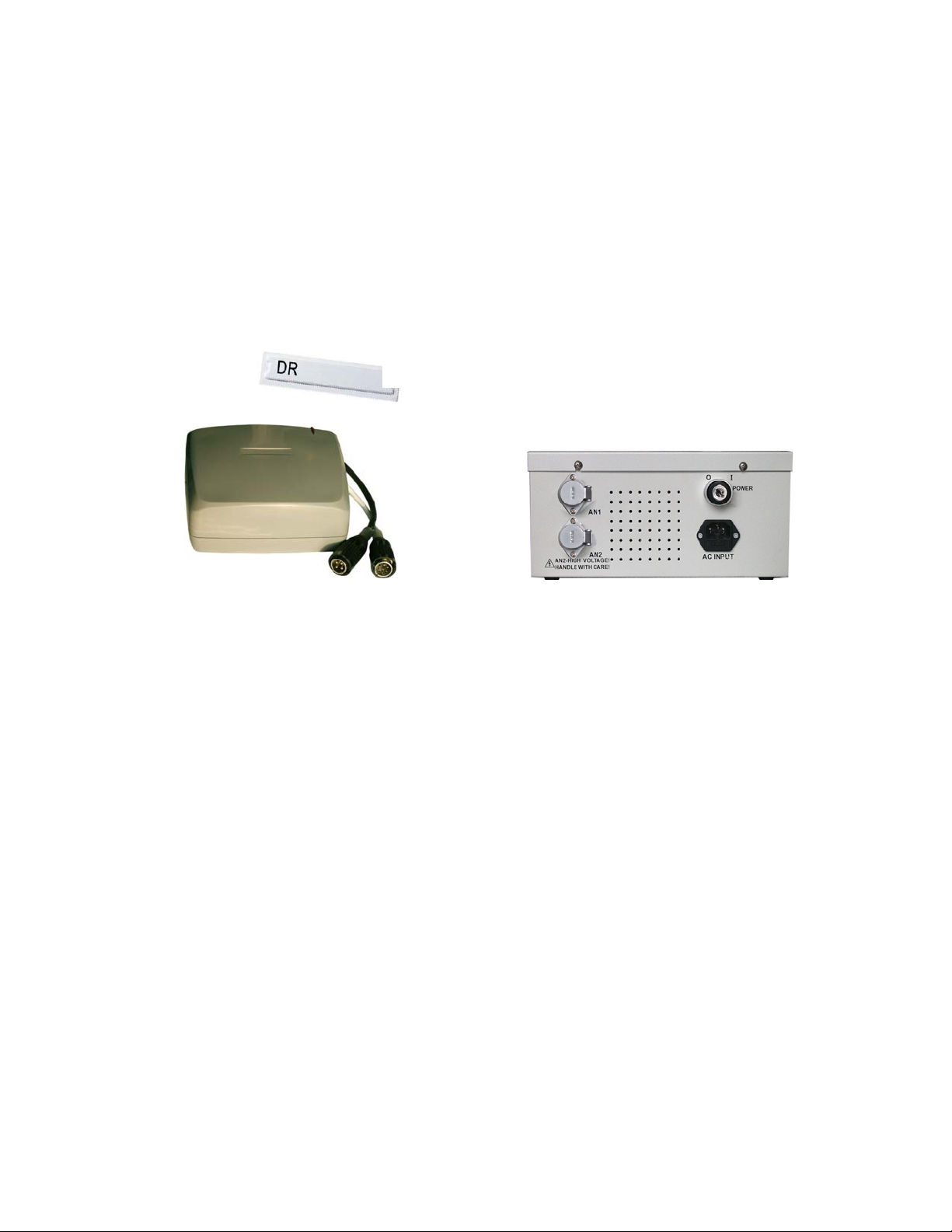
StealthPad Antenna
Double Resonant Labels
StealthPad Control Box
Features
Compactness
Its small footprint makes the antenna especially attractive in small counter tops.
Proximity Deactivation
The StealthPad offers distance deactivation, making it perfect for both source
tagged and retailer tagged merchandise.
Compact Size
The compact size of the deactivation antenna allows StealthPad to easily be
integrated into a counter application.
Integrated Audible and Visual Notification.
Label deactivation notification is built into the StealthPad.
LAN Accessible
StealthPad includes the remote access capability via WG’s optional EASNet
software for a variety of remote controls and data mining.
TM
1

Specifications
Electrical
Primary Input...................115±10%Va c, 60 Hz
230±10%Vac, 5 0Hz
Rated Current .................5A
Ac Operating Phase...........0°, 120°, or 240°
Transmitter Output .........1.6ms burst
Transmitter Current.........3A peak (nominal)
Operating Frequency .....58kHz
Mechanical
StealthPad Antenna
Length ............................188.1mm (7.4")
Width ...............................170mm (6.7")
Depth...............................80.4mm (3.2") (Include bottom feet)
Weight .............................3kg (6.6 lbs)
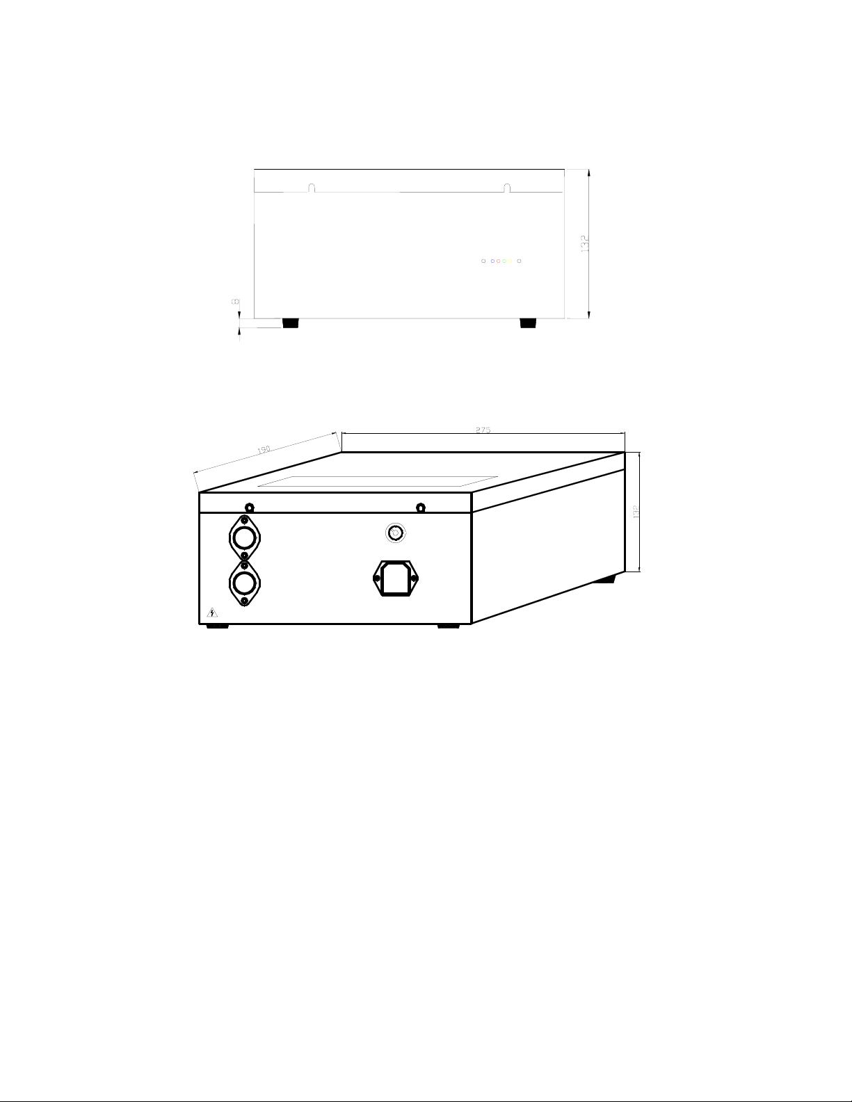
StealthPad Control Box
Length ............................275mm (10.8")
Width ...............................190mm (7.5")
Depth...............................140mm (5.5") (Include rubber feet)
Weight .............................3kg (6.6 lbs)
StealthPad Mounting Tray
Length ............................322mm (12.7")
Width ...............................307mm (12")
Depth...............................57mm (2.2")
Weight .............................0.24kg (0.53 lbs)
Environmental
Operating Temperature...0 to 49°C (32°–120°F)
Relative Humidity: ..........0 to 85% non-condensing
2
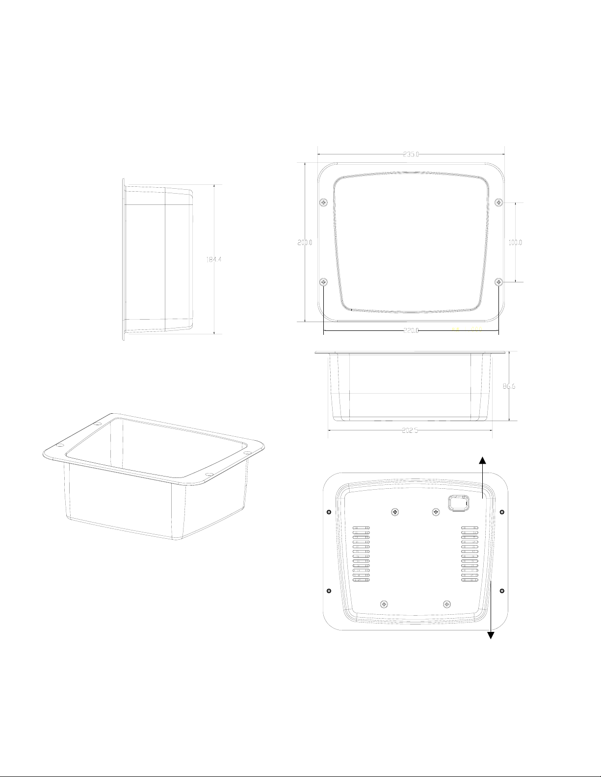
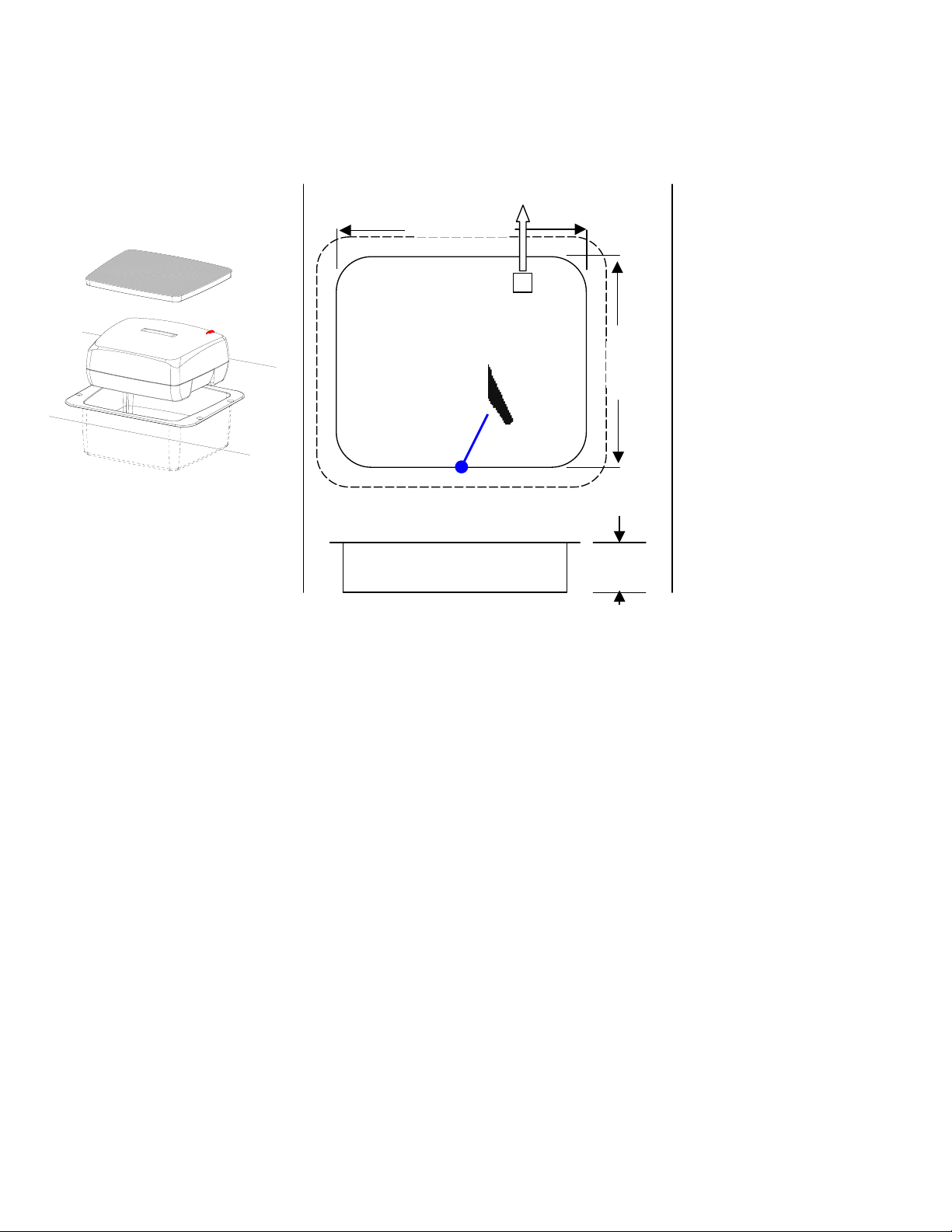
CAD Dimensions
A
PRE-INSTALLATION GUIDE
Flush Mount Tray
ll dimensions are in millimeters
Cable Outlet
Ventilation Holes
3
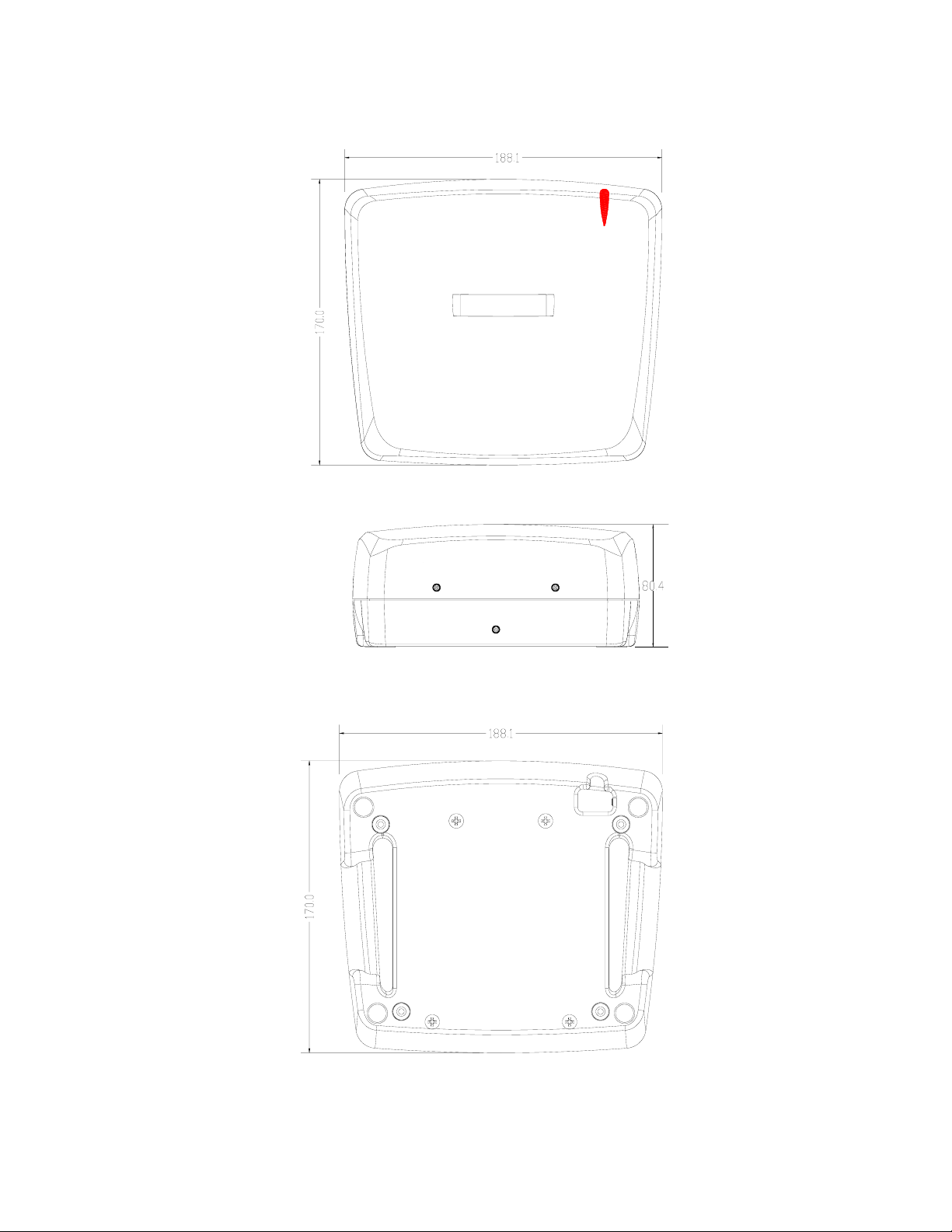
StealthPad Antenna (All dimensions are in millimeters)
4
AN2A
A
R
StealthPad Control Box (All dimensions are in millimeters)
N1
AN1
AN2
AN2-HIGH VOLTAGE !
CARE IN OPERATION
OFF
O
ON
C INPUT
AC INPUT
POWE
I
POWER
FAST PAD
TM
5
Flush Mount Cut Out Suggestion
(
)
203mm
8.0”
Cut
Cable Outlet
86.6mm 3.4”
185mm
(7.3”)
3cm free space around
pad for ventilation.
Antenna pad to control box
1.8m, 6 ft
Control box to AC
1.8m, 6 ft
Flange:
220.0x235.0mm
8.7”x 9.3”
Installation Site Power Supply Check
IT’S RECOMMENDED TO HAVE ALL STEALTHPADS ON THE SAME
POWER PHASE,otherwise you need to adjust B sync value step by step
to find a best position to sync different StealthPads connected to power
source with difference phase.
IT’S RECOMMENDED HAVING ENOUGH CURRENT SUPPLY FOR
STEALTHPADS IF THERE ARE MULTIPLE STEALTHPADS SHARING
ONE POWER SUPPLY. The rated current for StealthPad is 5A but the
suggested current draw for one StealthPad is 7-8A for better performance,
so a 15A power box will better serve 2 StealthPads instead of 3 or more.
IT’S RECOMMENDED HAVING GOOD GROUNDING FOR POWER
SUPPLY OF STEALTHPAD. (Some time the poor grounding and high
noise from power supply will decrease the sensitivity or detection range,
check Noise entry D1 and D2, a value over 6-7 will be considered as big
noise)
6
g
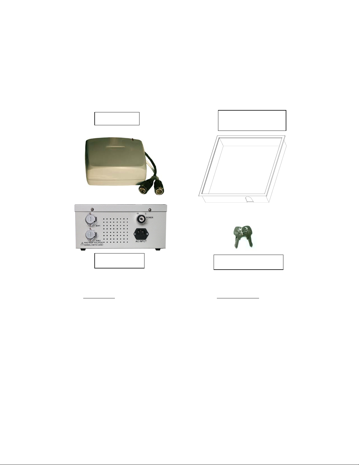
Parts List
Part Name
StealthPad for 110VAC power voltage
Antenna
Control Box (different than for FastPad)
StealthPad for 220VAC power voltage
Antenna
Control Box (different than for FastPad)
StealthPad Flush Mounting Tray
StealthPad Lock Key (the same as before)
INSTALLATION
Antenna (1)
Control box (1)
Order Number
StealthPad Lock Key
WG STP-1
WG STP-AT-1
WG STP-CB-1
WG STP-2
WG STP-AT-2
WG STP-CB-2
WG STP-FMT
WG-STP-KEY
Mounting tray (1)
for Flush Mountin
7
 Loading...