

Page 1

58Khz
Common Platform
EAS Systems
Installation Manual
April 2008
Manual Part Number: WG-
(Ver. 05040801)
Page 2
WG Security Products Inc. makes no representation or
warranty with respect to the contents hereof and
specifically disclaims any implied warranties of
merchantability or fitness for any particular purpose.
Further, WG Security Products Inc. reserves the right
to revise this publication and make changes from time
to time in the content hereof without obligation of WG
Security Products Inc. to notify any person of such
revision or changes.
WARRANTY DISCLAIMER
WG SECURITY PRODUCTS INC.
3031 Tisch Way, Suite 602, San Jose, CA 95128 (USA)
http://www.wgspi.com
Technical Support Contact Information
North America
South America
Rest of World
As specified by FCC Regulations 15.21, any
changes or modifications not expressly approved
by the party responsible for compliance of this
equipment, will void the user’s permission and
authority to operate this equipment.
Tel:
Fax:
Email: [email protected]
Tel: 408-241-8000
Fax: 408-241-8082
Email: support-row@ wgspi.com
CRITICAL NOTE
Page 3

TABLE OF CONTENTS
OVERVIEW ............................................... ................................................................... 1
System Overview ............................. ........................................................................... 1
System Configurations ................................................................................................. 2
Product Names and Part Numbers .................................................... ........................... 3
Common Platform Features & Benefits ......................................................................... 4
Specifications (common parameters) ............................................................................ 5
COMMON PLATFORM ELECTRONICS ..................................................................... 6
Board Functions Description ............................................. ........................................... 6
PCB Sockets & Connections ........................................................................................ 7
PCB Jumpers .................................................. .... .... ........ .... .... ........ .... ... .... ........ .... .... 8
Pedestal Tuning Access ....................................................... ....................................... 9
Antenna Channels on Transceiver Board .................................................................... 10
Fuse Replacement Information (Transceiver PCB) ............................................... 11
SMART POWER SUPPLY (SPS) ......................................... .... .... .... ....... .... .... .... .... .. 12
SPS Controls and Connections ................................................. ................................. 12
SPS Box Terminals Illustration ................................................................................... 13
SPS Box Main AC Input and Voltage Setup .......................................... ...................... 14
Interconnection between Smart Power Supply and Pedestal ........................................ 15
Power Cord Notices ........................... .... .... ........ .... .... ........ .... .... .... ....... .... .... .... ...... 16
SPS Box External Relay interface ............................................................ .................. 17
Page 4

Page 5
Common Platform EAS Systems
OVERVIEW
System Overview
Note: Common Platform EAS Systems differ only in the antennas that are used. All
systems use a universal transceiver printed circuit board that performs all the
functions of transmitting, receiving and alarm notification. This manual applies to
AdGuard, AdGuard XL, Lane Guard and Diamond Door Guard.
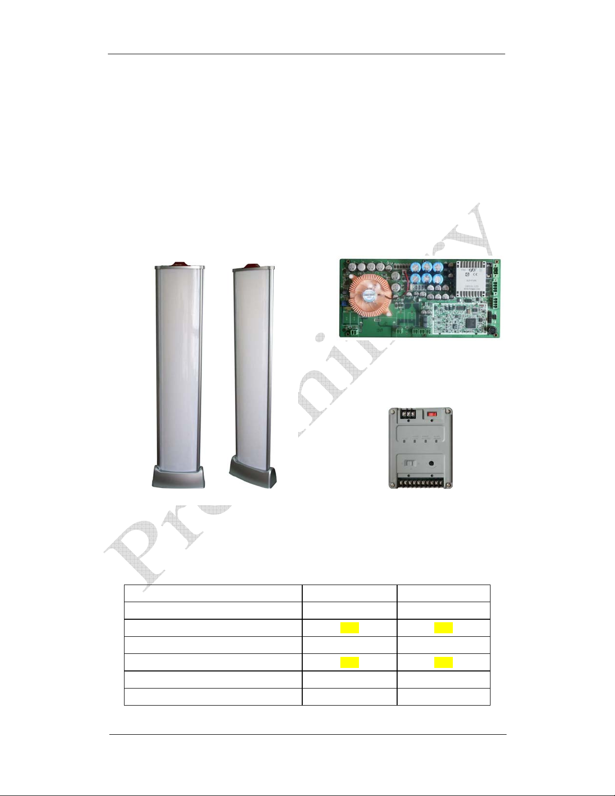
The common platform line of products consist of one or more pedestals (transceiver antenna
and optional extender), and one external PSU unit (WG SPS24). The transceiver pedestal
has one universal transceiver board which transmits and receives utilizing highly advanced
signal process technology, offering unsurpassed stability and detection performance.
Transceiver Antenna and Extender
Detection Range on Both Sides of Antennas with Micro Pencil Tags
24vac Smart Power Supply Unit
(AdGuard)
Transceiver PCB
(SPS)
Antenna Type Europe USA
AdGuard 0.9 m 3 ft
AdGuard wit h E xtender TBD TBD
AdGuard XL 1.4 m 4.5 ft
AdGuard XL with Extender TBD TBD
Lane Guard 0.9 m 3 ft
Diamond Door Guard 0.9 m 3 ft
1
Page 6
Common Platform EAS Systems
System Configurations
Each transceiver pedestal is powered by its own dedicated SPS. The common platform SPS
not only provides 24vac power to the transceiver pedestal, but it includes some very important
features.
• Accepts a wide AC input voltage ranges
• Controls transmitter bursts for troubleshooting
• Adjusts pedestal alarm volume
• Provides alarm visual & audio indication and relay output
• Provides Jammer Detection alarm and relay output
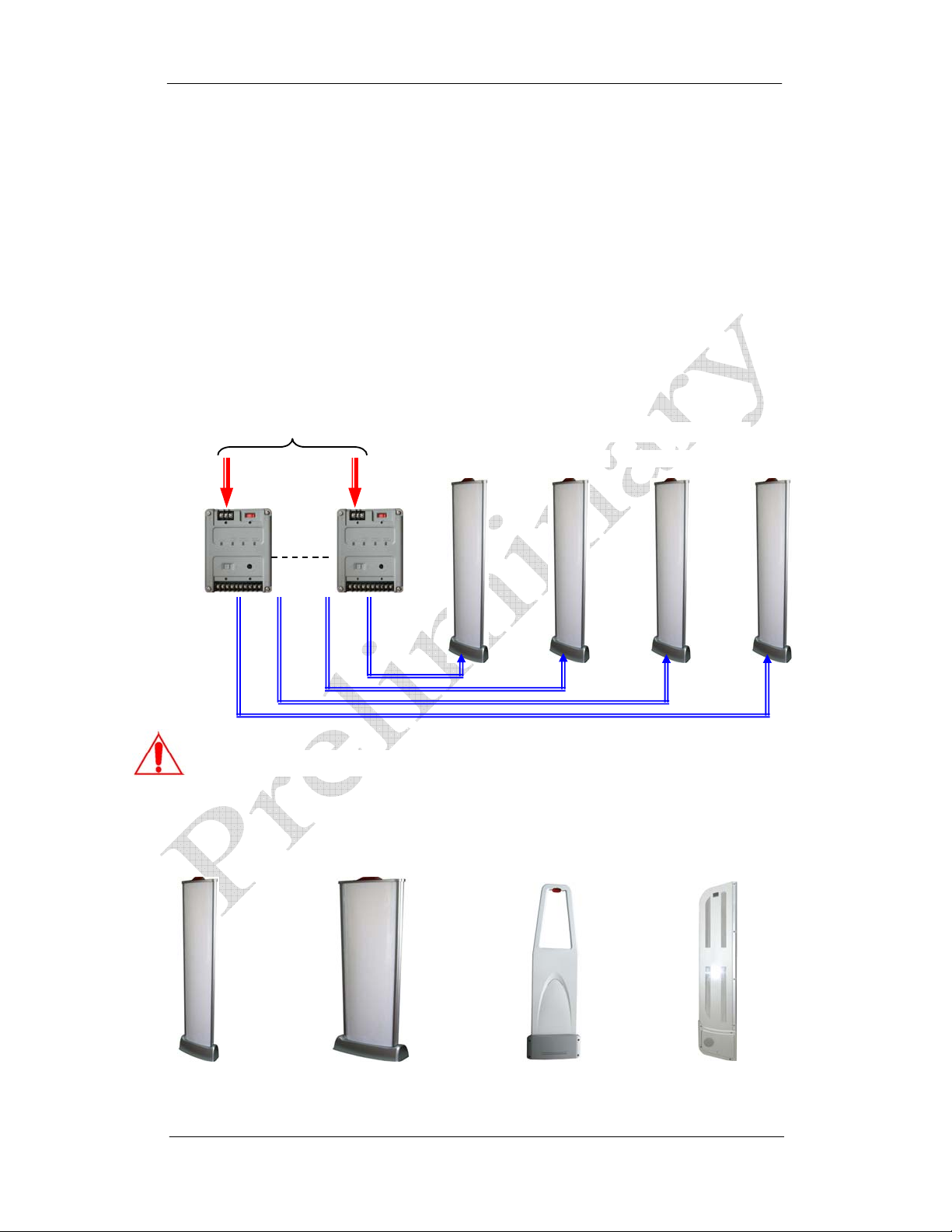
24vac power and data/control is carried by a single TX cable from the SPS to the pedestal.
Each SPS is individually powered. This picture depicts and example where 4 power supplies
are integrated into a single industry standard rack with main power input and to which each
SPS is then connected.
Caution! One SPS can only power only one transceiver pedestal.
The Common Platform Product Line includes any of the following antenna models.
AdGuard AdGuard XL
AC Input
Example: AdGuard Transceiver Antennas
Pedestal A
Pedestal B Pedestal C Pedestal D
Power & Control
Diamond Door GuardLane Guard
2
Page 7
Common Platform EAS Systems
Product Names and Part Numbers
Accessories
Accessory Name
1. Smart Power Supply (SPS unit) WG SPS24
2. Instruction Manual
3. Power Line Connector (2 pins)
4. Communication Connector (4 pins)
5. Laptop Tuning Software
(includes WG USB Cable)
6. USB Tuning Cable
7. WG IR Tuning Module
Systems
Antenna Name
1. AdGuard Transceiver Pedestal WG AGTR24
2. AdGuard Extender Pedestal WG AGTR-EX
3. AdGuard XL Transceiver Pedestal WG AGXTR24
4. AdGuard XL Extender Pedestal WG AGXTR-EX
5. Lane Guard Transceiver Pedestal WG LGTR24
6. Diamond Door Guard Transceiver WG DG2TR24
Order Number
Order Number
TBD
TBD
TBD
TBD
TBD
TBD
3
Page 8

Common Platform EAS Systems
Common Platform Features & Benefits
• All-in-One platform design for the Acousto-Magnetic (AM) product line makes it a
perfect AM detection core solution for various antenna forms and needs. There are
visible advantages on short term and long term operation along with low cost
maintenance.
• Unprecedented Digital Signal Processing Technology
The common platform line brings an ever advancing DSP technology to an
unprecedented level compared with traditional anti-theft solutions, eliminating false
alarms and maintaining a considerable detection range.
• Universal Mobile PC Tuning Interface
Benefiting f rom its highly performance- rich digital pr ocessing con troller, the c ommon
platform can connect to laptop PC through the popular USB port.
• Anti-Jammer Alarm
The Anti-Jammer alarm function addresses the modern high-tech theft actions that
defeat the Acousto-Magnetic detection system with DIY jamming devices. WG’s
common platform design detects and alerts security personnel as soon as the jammer
device attempts to defeat the transceiver pedestal.
• Local and Remote Audible and Visual Notification
Alarm flexibility provides local alarming at the pedestal plus remote alarm notification
through the SPS via convenient visual and external ports.
• Transceivers can be individually optimized for label or ferrite tag detection.
4
Page 9

Common Platform EAS Systems
Specifications (common parameters)
Smart Power Sup pl y (S PS) Electrical
Primary Input
(Stepdown Transformer)
Secondary Output
Rated Output Current
Maximum Secondary
Output Current
Built-in Fuse (self recovery) 500mA
Smart Power Su pp l y (S PS ) Me ch a n i cal
Height 80mm ( 3.15” )
Width 110mm ( 4.33” )
Thickness 140mm ( 5.5” )
Weight 3 Kg ( 6.6 lbs)
100vac ±10 %
110vac ±10 %
120vac ±10 %
220vac ±10 %
240vac ±10 %
26Vac ±5 %
1.4A ±5 %
1.9 A
Environmental (Pedestals and SPS)
Operating Temperature
Relative Humidity 0 to 85% non-condensing
Mechanical (Pedestals)
AdGuard Pedestal
AdGuard XL Pedestal
Lane Guard
(w/o brackets)
Diamond Door Guard
TBD °C (°F)
66”H x 12.6”W x 3”D (166 x 33 x 7.6cm)
Weight (TBD)
66”L x 18.5”W x 3.54”H (166 x 48 x 8.6cm)
Weight (TBD)
52.8”L x 14.4”W x 1.5”H (134 x 36.7 x 3.8cm)
Weight (TBD)
59”L x 12.2”W x 2”H(150 x 31 x 5cm)
Weight (TBD)
5
Page 10
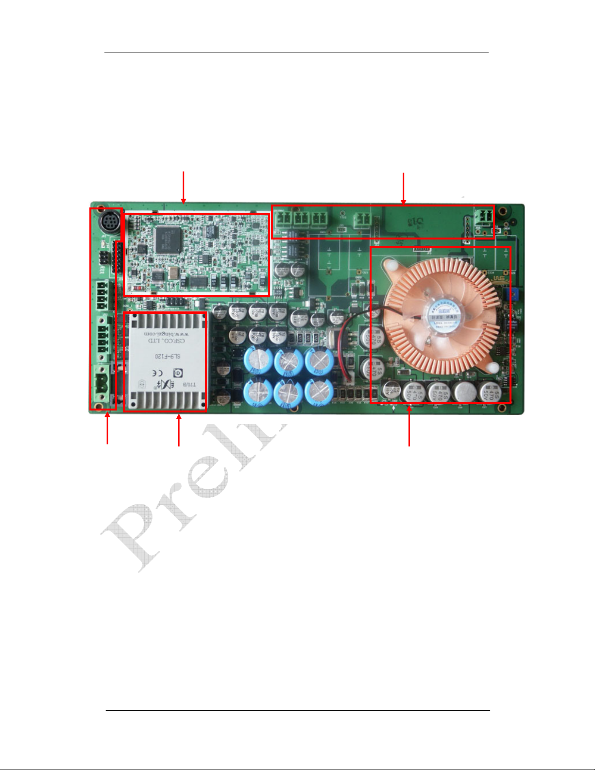
Common Platform EAS Systems
COMMON PLATFORM ELECTRONICS
Board Functions Description
Receiver Area
Antenna Sockets
External Sockets
Transformer
Transmitter
6
Page 11
Common Platform EAS Systems
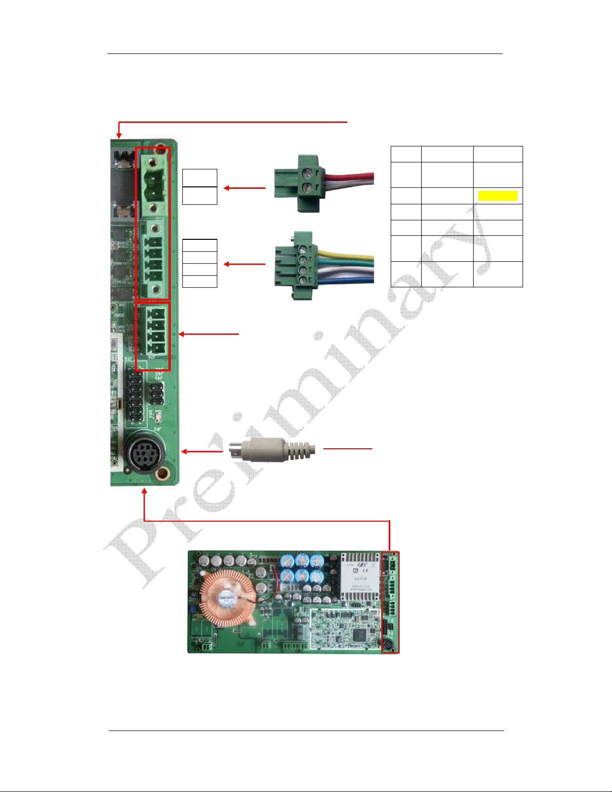
PCB Sockets & Connections
Pin1
Pin2
Pin3
Pin4
Pin5
Pin6
Pedestal Loc al A l ar m an d LE D C on n e c to r
2-Pin Power Connector
4-Pin Control Connect or
Board Power Input Fuse
Pin # Function I/O
1 GND
2 24VAC
3 TX OFF Output
4 Alarm Input
5
6
Anti-
Jammer
Alarm
Volume
Common
GND
26vac±5%
Input
Output
USB connection cable
or IR Tuning Module
7
Page 12
Common Platform EAS Systems
g
A
S
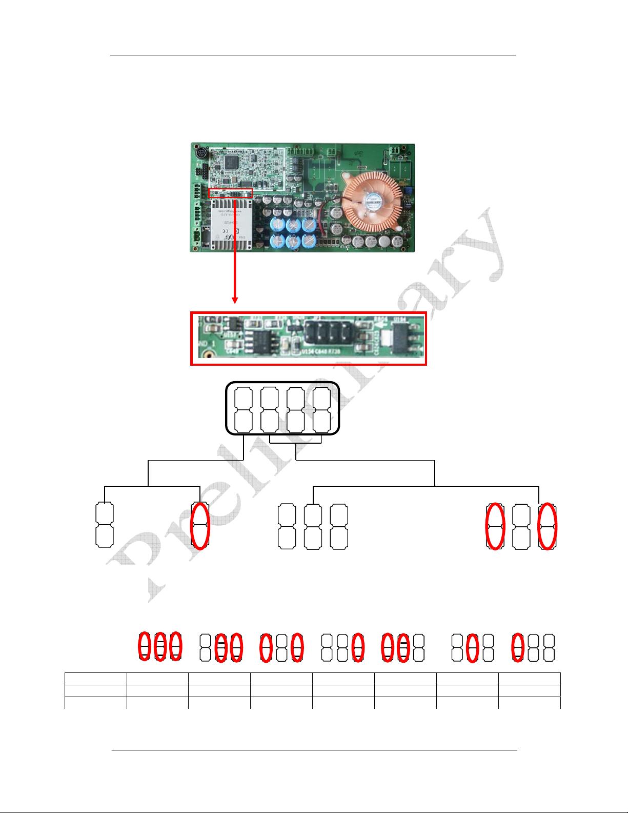
PCB Jumpers
There is only one set of Jumper that is subject to User’s configuration; all other jumpers
please keep them as original as system is delivered.
Jumper Configurations
Gain Settings Ferrite and Re s onator Settin
L
B MSB
W/ Jumpers:
Jumpers
Controlled Gain
Empty:
Ferrite and
Resonator
Gain Value
Lookup
Table
W/ Jumper:
Resonator
ONLY
ll Empty:
Board Software
Controlled Gain
Binary 0 0 0 1 0 0 0 1 0 1 1 0 0 0 1 1 0 1 0 1 1
Decimal 0 1 2 3 4 5 6
Gain value
8
Page 13
Common Platform EAS Systems
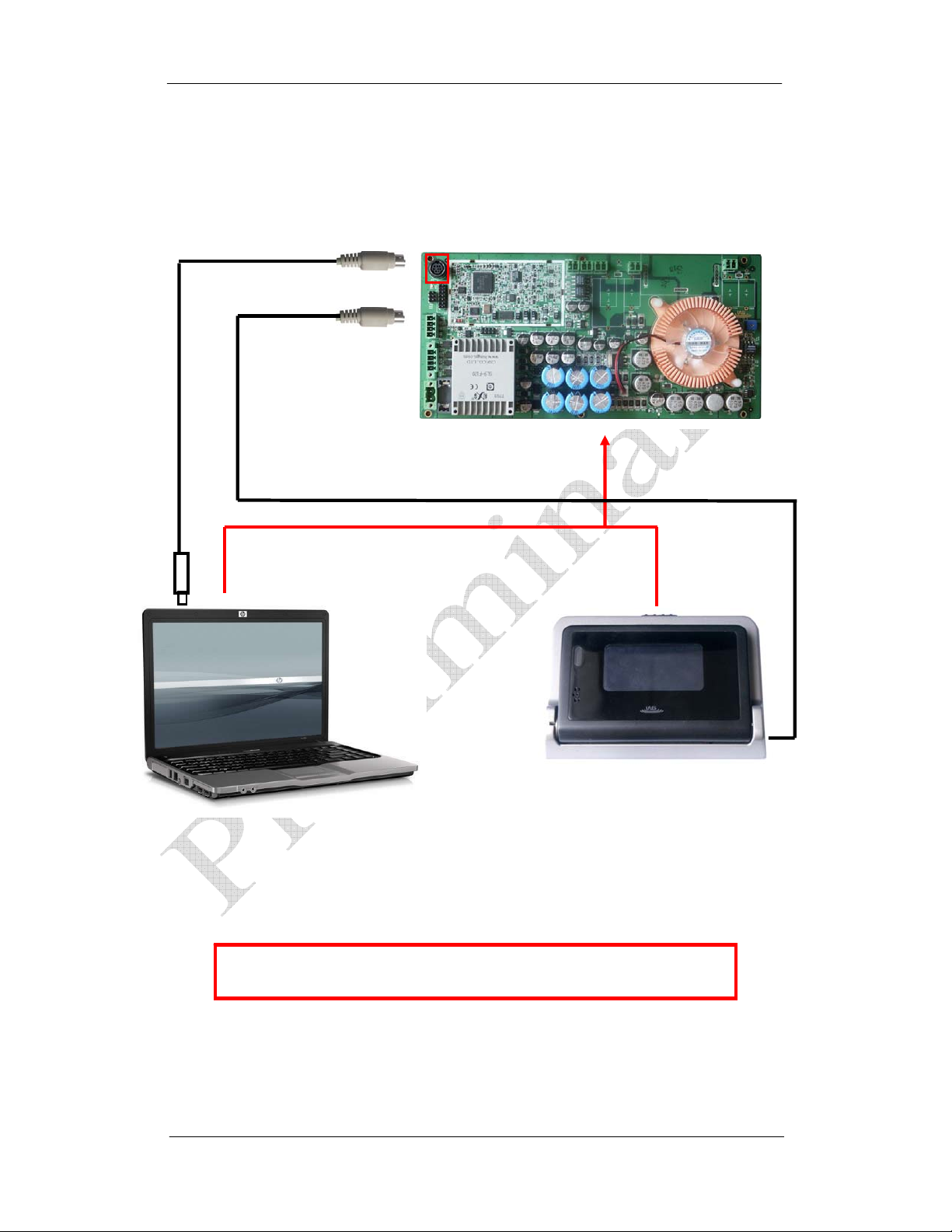
Pedestal Tuning Access
Common Platform systems include advanced tuning features that offer the technician a
choice of access. There is a connector on the Transceiver PCB for tuning access. The
installer can connect to the pedestal using a laptop PC with a WG USB cable or attach an
external IR tuning and display module. The same dedicated tuning connector on the
transceiver board accepts both the WG USB cable and external IR tuning and display module.
WG USB Cable
Pedestal tuning access using a laptop
PC is through the WG USB cable.
WG IR Module
Laptop PC
IR Module
Pedestal tuning access using the WG
IR tuning module offers the external
display interface and traditional
remote control interface.
Laptop tuning software with WG USB cable and IR Tuning Module are
optional and must be ordered separately from WG Security Products.
9
Page 14
Common Platform EAS Systems
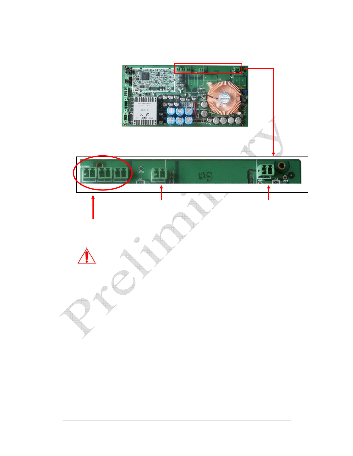
Antenna Channels on Transceiver Board
Receiver Connectors
TX-B
To Loop Antenna
TX-A and TX-B sockets connect to the two types of coil antennas.
They must not be transposed; strictly follow the illustration.
TX-A
To Figure 8 Antenna
10
Page 15
Common Platform EAS Systems
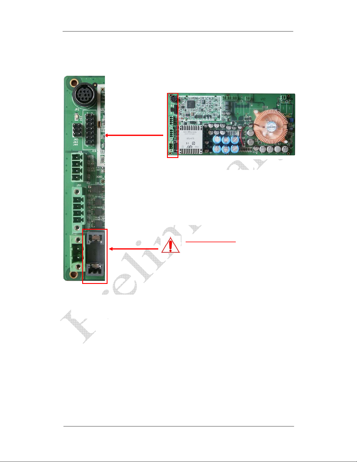
Fuse Replacement Information (Transceiver PCB)
The fuse holder is accessed through the pedestal side panel.
WARNING – TO REDUCE THE RISK OF DAMAGE, REPLACE ONLY WITH
THE SAME FUSE TYPE AND RATING.
1. Equipment shall be electrically disconnected from
the main circuit supply when replacing the fuse.
2. Remove the fuse holder with a screwdriver,
rotating it in a counterclockwise direction.
3. Replace the fuse in accordance with the
specification noted above.
Fuse Replacement:
5mm x 20mm
3.15A (Normal Fuse)
2.5A (Slow Blow Fuse)
11
Page 16
Common Platform EAS Systems
SMART POWER SUPPLY (SPS)
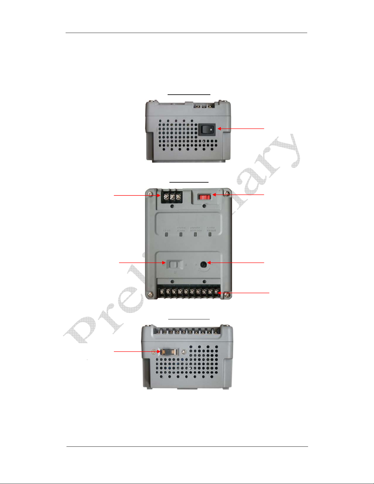
SPS Controls and Connections
Main AC Power In
TX Antenna
On/Off Switch
Input Voltage
Select Switch B
SPS Front View
SPS Power
On/Off Switch
SPS Top View
Input Voltage
Select Switch A
Pedestal Alarm
Volume Adjust
24vac
Power & Data
Output
SPS Rear View
12
Page 17
Common Platform EAS Systems
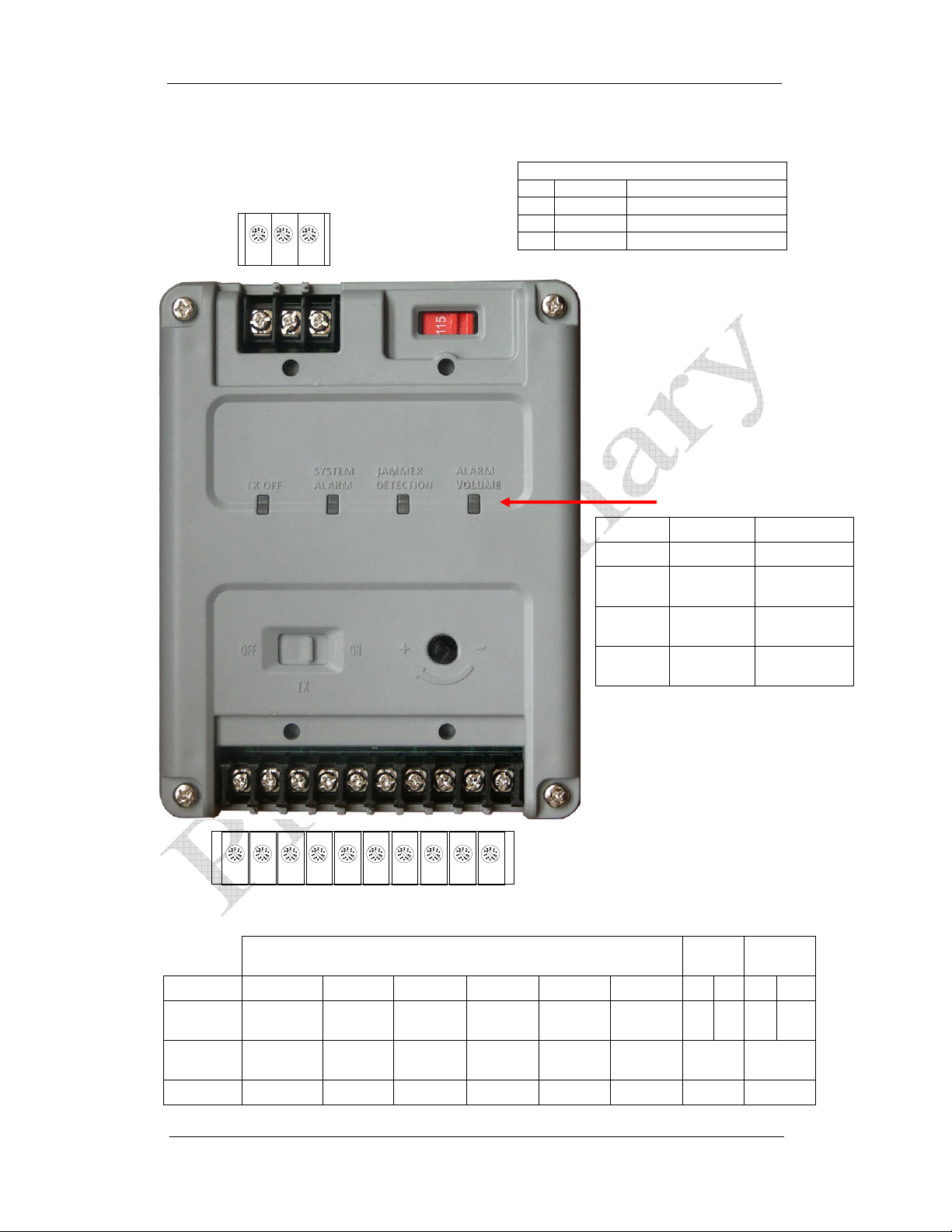
SPS Box Terminals Illustration
N - GND - L
Pin:
1
2
3
Main AC
Input
Terminal
Pin:
1
2
4 5 6 7 8 9 10
3
SPS Main AC Input Terminal Layout
Main AC Cable (3 wires)
Pin Function Color
1 Neutral Blue
2 Ground Green w/Yellow Stripe
3 Live Red(Brown)
LED Status
LED On Off
TX Off TX is Off TX is On
System
Alarm
Jammer
Detection
Alarm
Volume
Alarm
Enabled
Detection
Enabled
Dim Means
Weaker
Bright Means
Alarm
Disabled
Detection
Disabled
Louder
SPS Output Terminal Layout (10 pins)
Pin # 1 2 3 4 5 6 7 8 9 10
Function GND 24VAC TX OFF Alarm
Electrical
I/O Output Output Output Input Input Output Output Output
Common
GND
SPS to Pedestal Cable (6 wires)
26
VAC
>4.0vdc <2.5vdc <2.5vdc 5-15vdc
13
Anti-
Jammer
Alarm
Volume
Alarm
Relay
1A
Contact
Jammer
Relay
1A
Contact
Page 18
Common Platform EAS Systems
A
SPS Box Main AC Input and Voltage Setup
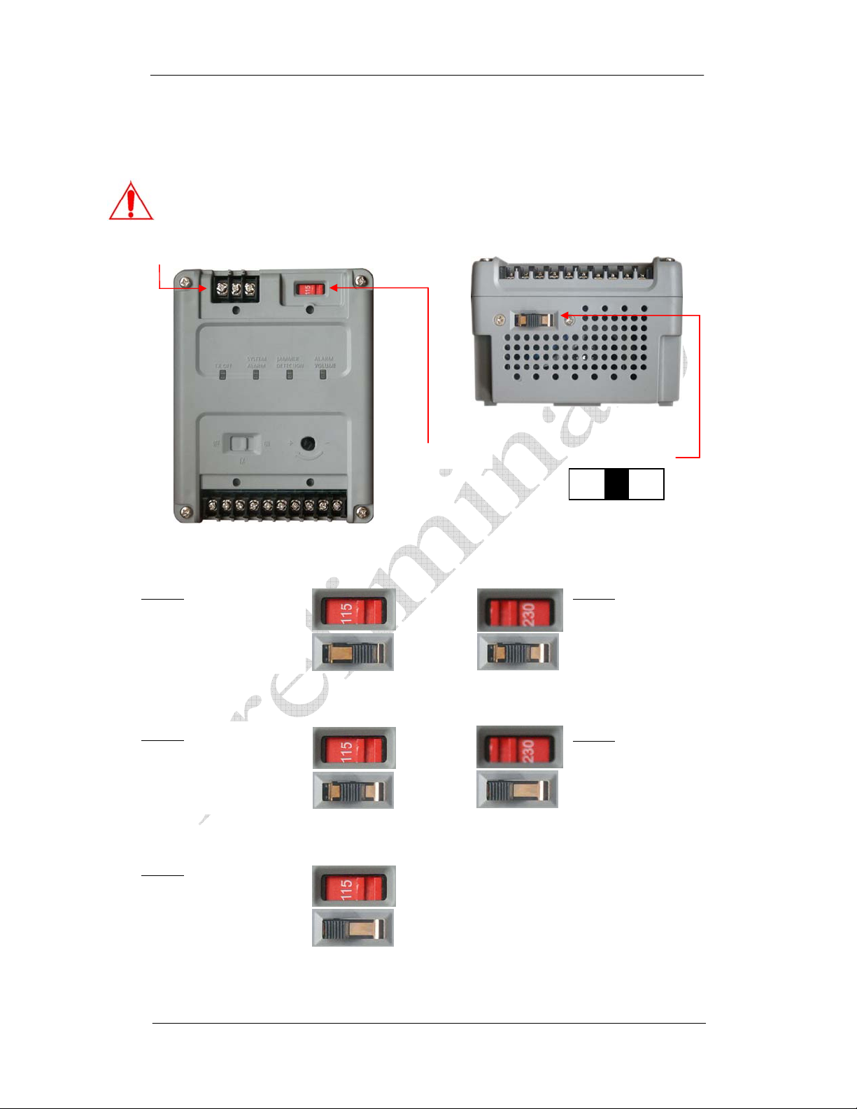
The Smart Power Supply (SPS) box accepts 5 input voltages: 100vac 110vac and 120vac in
North America and Japan, 220vac and 240vac in Europe and Australia.
Caution: Set the two Voltage Switches (A and B) o n the SPS at the specified
combination based on the local incoming voltage value (see picture below).
C Power In
100vac
Voltage Switch A - 115
Voltage Switch B - LOW
110vac
Voltage Switch A - 115
Voltage Switch B - MIDDLE
120vac
Voltage Switch A - 115
Voltage Switch B - HIGH
Voltage Switch A
Voltage Switc h B
HIGH MID LOW
(Three Positions)
220vac
Voltage Switch A - 230
Voltage Switch B - MIDDLE
240vac
Voltage Switch A - 230
Voltage Switch B - HIGH
14
Page 19
Common Platform EAS Systems
r
Interconnection between Smart Power Supply and Pedestal
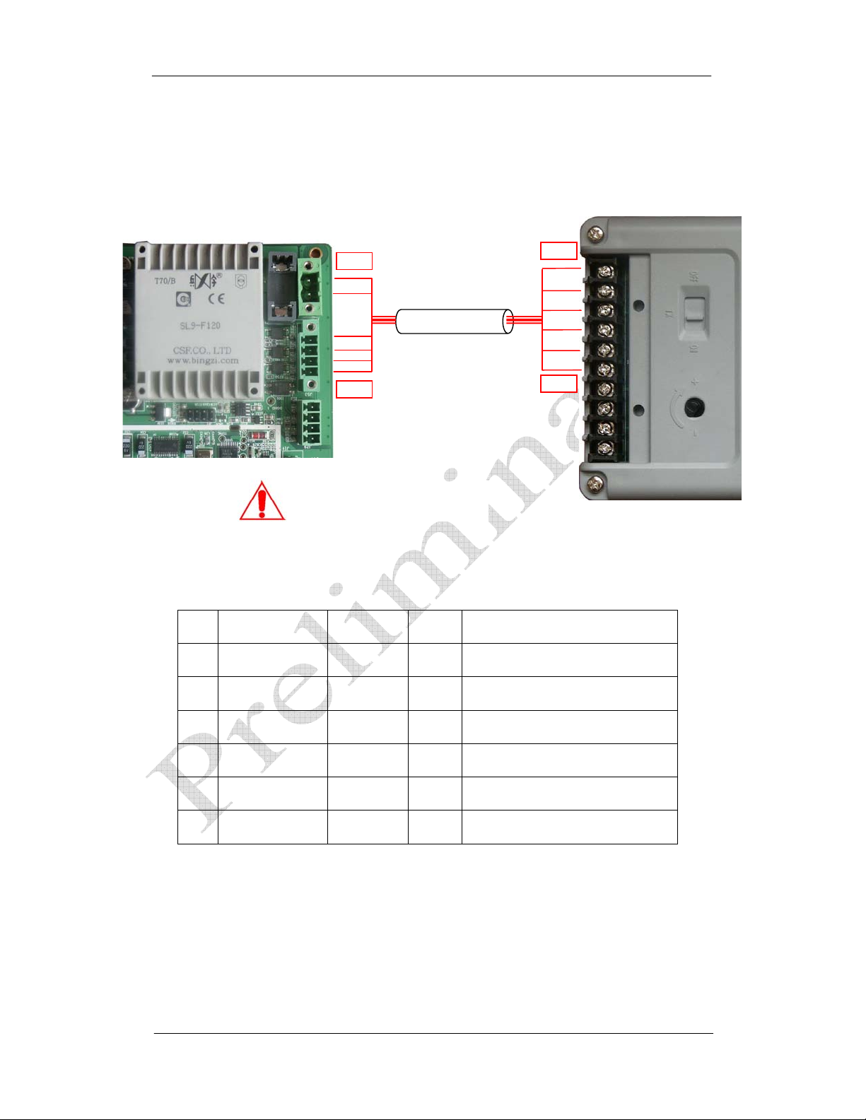
The system transceiver board has two sockets (combined pins 1 to 6) that connect to SPS
output terminal pins 1 to 6 (one-to-one pin connection). The reference diagram shows the pin
mapping relation between transceiver board and PSU.
Cable Conductors Specifications
Note: Specifications are calculated at 30 meters (100 feet) length.
Pin Conductors Gauge AWG Description
1 Conductor 1 1 mm 2 16 Power (Common Ground)
2 Conductor 2 1 mm 2 16 Power (26 Vac)
3 Conductor 3 0.5 mm 2 20 TX OFF
4 Conductor 4 0.5 mm 2 20 Alarm
5 Conductor 5 0.5 mm 2 20 Jammer-Detection
6 Conductor 6 0.5 mm 2 20 Alarm Volume
Caution! One SPS can powe
only one transceiver pedestal.
Isolated Multiple Conductor Cable
Pin 1
Un-Shielded
Pin 6
Pin 1
Pin 6
15
Page 20
Common Platform EAS Systems
Power Cord Notices
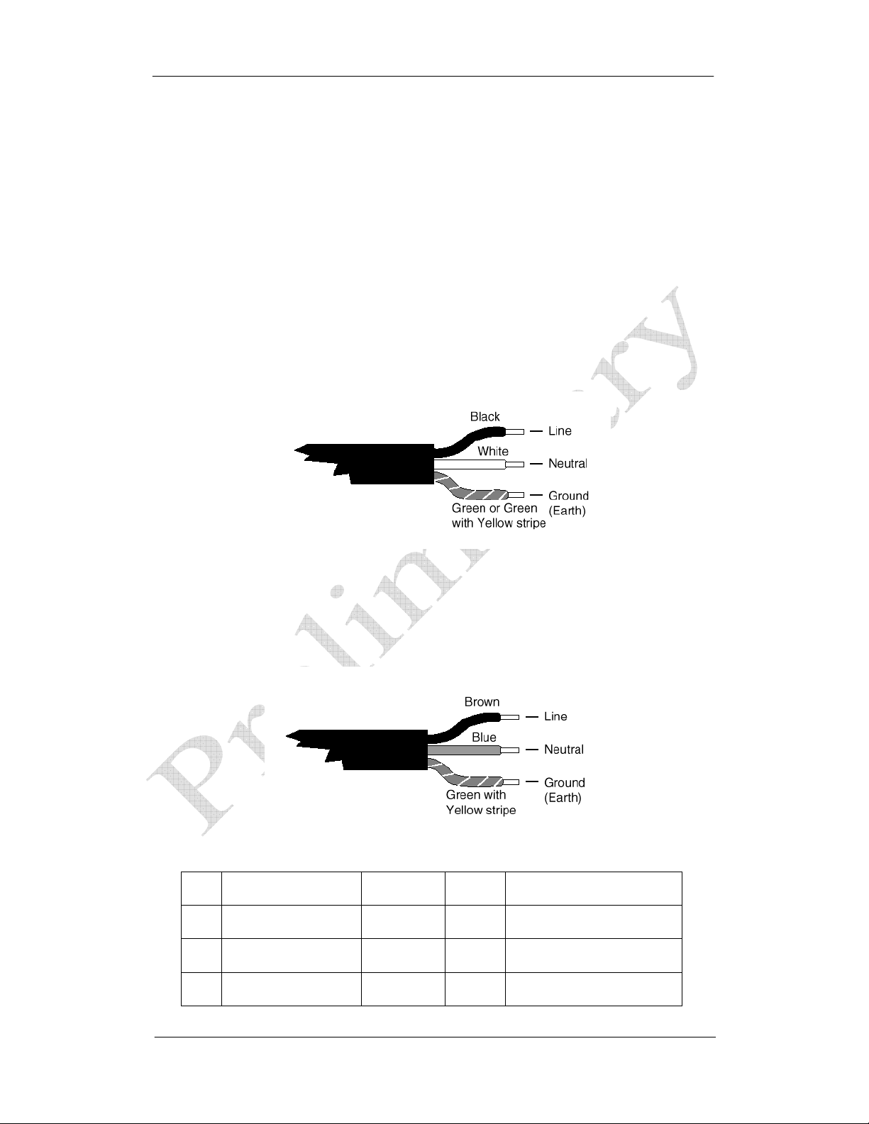
The SPS delivered does not include AC cable for installation except a short testing cable; we
recommend that you use a CE approved po wer cord H05 VV-F or H05 VVH2- F2 (Refer to the
Electrical code which governs your country for installation of an Anti-Theft Unit to the Main
power Supply) with the cable specification and gauge provided below.
North American Power Supply Cords
This equipment is supplied with an external power line at one end and a
molded receptacle terminal block at the other end. Conductors are color coded
white (neutral), black (line) and green or green/yellow (ground).
Operation of this equipment at voltages exceeding 130 VAC will require power
supply cords which comply with NEMA configurations.
International Power Supply Cord
This equipment is supplied with an external power line at one end and a
molded receptacle terminal block at the other end. Conductors are CEE colorcoded—light blue (neutral), brown (line) and green/yellow (ground). Other IEC
320 C-13 type power supply cords can be used if they comply with the safety
regulations of the country in which they are installed.
Main AC input Cable Specifications.
Pin Conductors Gauge AWG Description
1 Conductor L 0.75 mm 2 18 Main AC Live
2 Conductor N 0.75 mm
2
18 Main AC Neutral
3 Conductor GND 0.75 mm 2 18 Main AC Gnd
16
Page 21
Common Platform EAS Systems
SPS Box External Relay interface
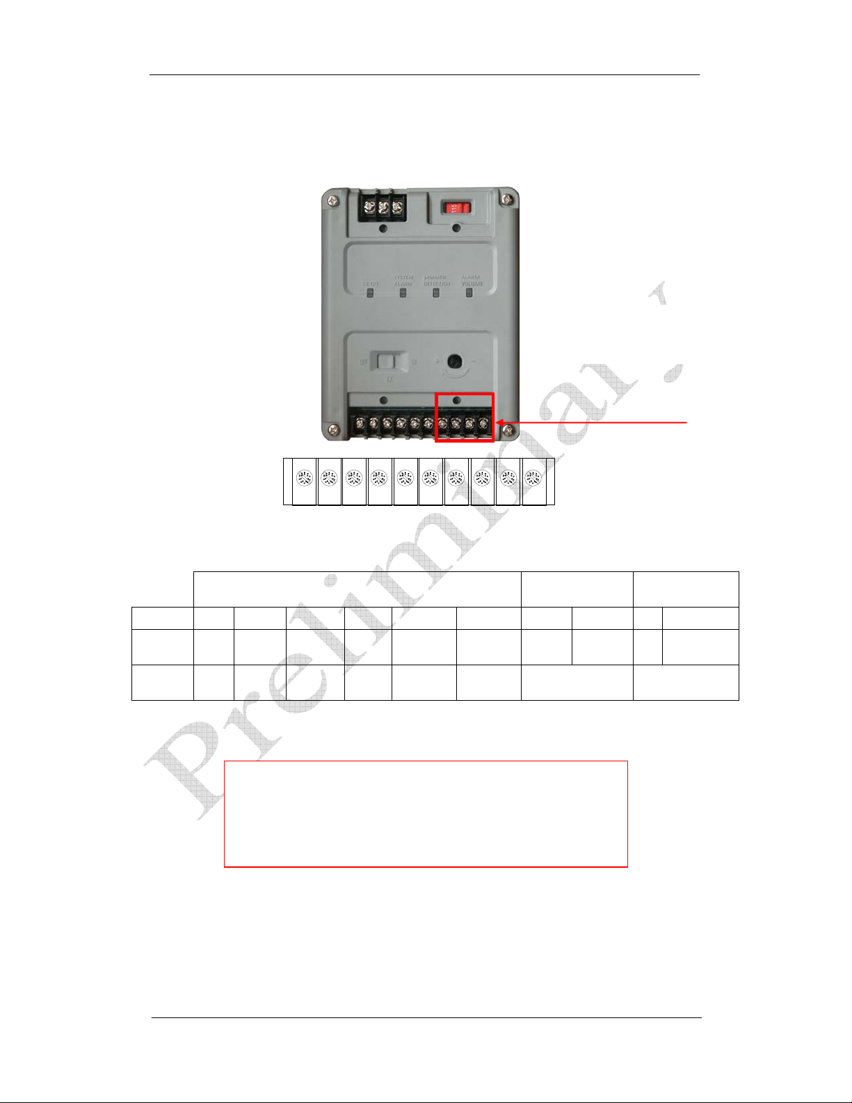
The external relay interface is located at Output side of the SPS.
Suggested Relay Ratings
1A@ 24 VDC
Last 4 pins on this end.
Pin # 1 2 3 4 5 6 7 8 9 10
Function GND 24VAC TX OFF Alarm
Electrical
Notes:
1. Wire length to the dry contact circuit is limited to 20 feet.
2. To prevent high voltage noise from being introduced into
Pin 1 Pin 2
SPS Output Terminal Layout (10 pins)
SPS to Pedestal Cable (6 wires)
the transceiver and degrading the system’s performance,
it is highly recommended that you use a 24vdc output
relay.
Pin 4Pin 5Pin 6 Pin 7 Pin 8Pin 9 Pin 10
Pin 3
Anti-
Jammer
***
Alarm
Volume
Alarm
Relay
1A
Contact Rating
Jammer
Relay
Contact Rating
1A
17
 Loading...