

WG Security WGBTLLG User Manual

TM
58Khz
BTL Common Platform
EAS Systems
(EAS4.0 ver1.1 AM board)
Installation Manual
February 2012
Manual Part Number:
(Ver. )

“This device complies with Part 15 of the FCC Rules. Operation is
subject to the following two conditions: (1) This device may not cause
harmful interference, and (2) This device must accept any interference
received, including interference that may cause undesired operation.”
WG Security Products Inc. makes no representation or
warranty with respect to the contents hereof and
specifically disclaims any implied warranties of
merchantability or fitness for any particular purpose.
Further, WG Security Products Inc. reserves the right
to revise this publication and make changes from time
to time in the content hereof without obligation of WG
Security Products Inc. to notify any person of such
revision or changes.
WARRANTY DISCLAIMER
FCC ID: P9I-WGBTLLG
This equipment has been tested and found to comply with the limits for a class B
digital device, pursuant to Part 15 of the Federal Communications Commission (FCC)
rules. These limits are designed to provide reasonable protection against harmful
interference in a residential installation. This equipment generates, uses, and can
radiate radio frequency energy and, if not installed and used in accordance with the
instructions, may cause harmful interference to radio communications. However,
there is no guarantee that interference will not occur in a particular installation. If this
equipment does cause harmful interference to radio or television reception, which
can be determined by turning the equipment off and on, the user is encouraged to try
to correct the interference by one or more of the following measures:
‧ Reorient or relocate the receiving antenna.
‧ Increase the separation between the equipment and receiver.
‧ Connect the equipment into an outlet on a circuit different from that to which the
receiver is connected.
‧ Consult the dealer or an experienced radio/TV technician for help.
The use of a shielded-type power cord is required in order to meet FCC emission
limits and to prevent interference to the nearby radio and television reception. It is
essential that only the supplied power cord be used. Use only shielded cables to
connect I/O devices to this equipment. You are cautioned that changes or
modifications not expressly approved by the party responsible for compliance could
void your authority to operate the equipment.
Note:
Any changes or modifications not expressly approved by the grantee of this device
could void the user's authority to operate the equipment.
RF exposure warning
This equipment complies with FCC radiation exposure limits set forth for an
uncontrolled environment.This equipment must be installed and operated in
accordance with provided instructions and the antenna(s) used for this transmitter

WG SECURITY PRODUCTS INC.
3031 Tisch Way, Suite 602, San Jose, CA 95128 (USA)
http://www.wgspi.com
Technical Support Contact Information
Tel: 949-545-6005
North America
South America
Rest of World
As specified by FCC Regulations 15.21, any
changes or modifications not expressly approved
by the party responsible for compliance of this
equipment, will void the user’s permission and
authority to operate this equipment.
Toll Free: 888-633-5095
Fax: 949-545-6011
Email: service@wgspi.com
Tel: 4+49 8654 7715-21
Fax: 4+49 8654 7715-21
Email: support-ROW@wgspi.com
CRITICAL NOTE

TABLE OF CONTENTS
OVERVIEW................................................................................................................1
System Overview.................................................................................................... 1
System Configurations............................................................................................2
Product Names and Part Numbers......................................................................... 3
Common Platform Features & Benefits ..................................................................4
Specifications (common parameters) ..................................................................... 5
COMMON PLATFORM ELECTRONICS....................................................................6
BTL AM Board Functions Description.....................................................................6
Antenna Channels on BTL AM Board ..................................................................... 7
TX Amplitude POT on BTL AM Board .................................................................... 8
BTL AM Board to Socket Board Power Cables Connections..................................9
Pedestal Socket Board Connections .................................................................... 10
Fuse Replacement Information (on BTL socket Board)........................................ 12
Pedestal Tuning Access (on BTL AM Board) .......................................................13
SMART POWER SUPPLY (SPS) ............................................................................ 14
SPS Controls and Connections ............................................................................ 14
SPS Box Terminals Illustration.............................................................................15
SPS Box Main AC Input and Voltage Setup.........................................................16
Interconnection between Smart Power Supply and Pedestal...............................17
Power Cord Notices..............................................................................................18
SPS Box Mounting Instructions ............................................................................ 20
SPS Box External Relay interface ........................................................................ 21
Common Platform EAS Systems
OVERVIEW
System Overview
Note: Common Platform EAS Systems differ only in the antennas that are used. All
systems use a universal transceiver printed circuit board that performs all the
functions of transmitting, receiving and alarm notification. This manual applies to
AdGuard, AdGuard XL, Lane Guard and Diamond Door Guard.
The common platform line of products consist of one or more pedestals (transceiver antenna
and optional extender), and one external PSU unit (WG SPS24). The transceiver pedestal
has one universal transceiver board which transmits and receives utilizing highly advanced
signal process technology, offering unsurpassed stability and detection performance.
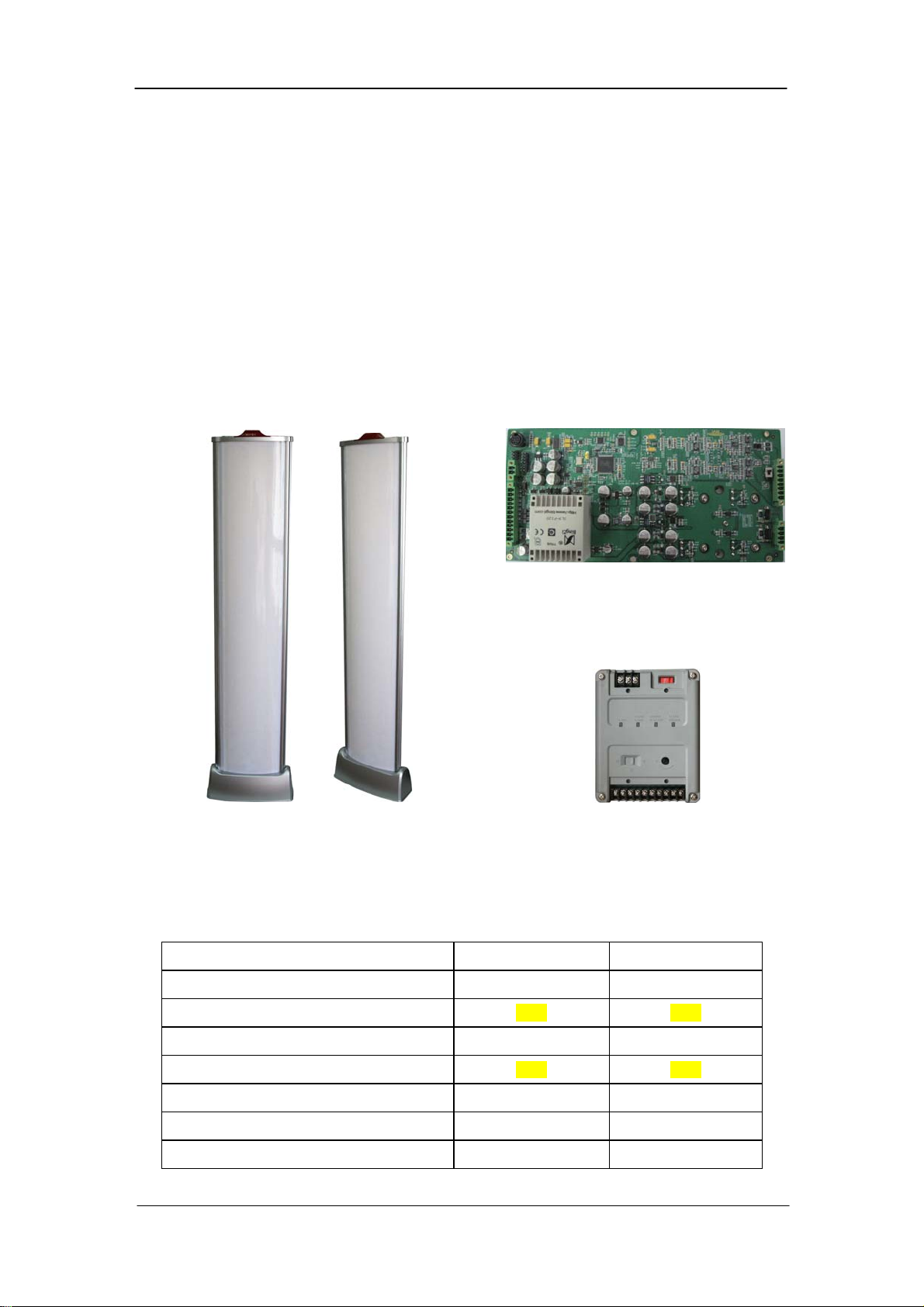
Transceiver Antenna and Slave
(AdGuard)
BTL Transceiver PCB ver1.1
24vac Smart Power Supply Unit
(SPS)
Detection Range on Both Sides of Antennas with Micro Pencil Tags
Antenna Type Europe USA
AdGuard BTL m ft
AdGuard BTL with Slave TBD TBD
AdGuard XL BTL m ft
AdGuard XL BTL with Slave TBD TBD
Lane Guard BTL m ft
Premier Guard BTL m ft
Premier Pro BTL m ft
1
Common Platform EAS Systems
System Configurations
Each transceiver pedestal is powered by its own dedicated SPS. The common platform SPS
not only provides 24vac power to the transceiver pedestal, but it includes some very important
features.
• Accepts a wide AC input voltage ranges
• Controls transmitter bursts for troubleshooting
• Adjusts pedestal alarm volume
• Provides alarm visual & audio indication and relay output
• Provides Jammer Detection alarm and relay output
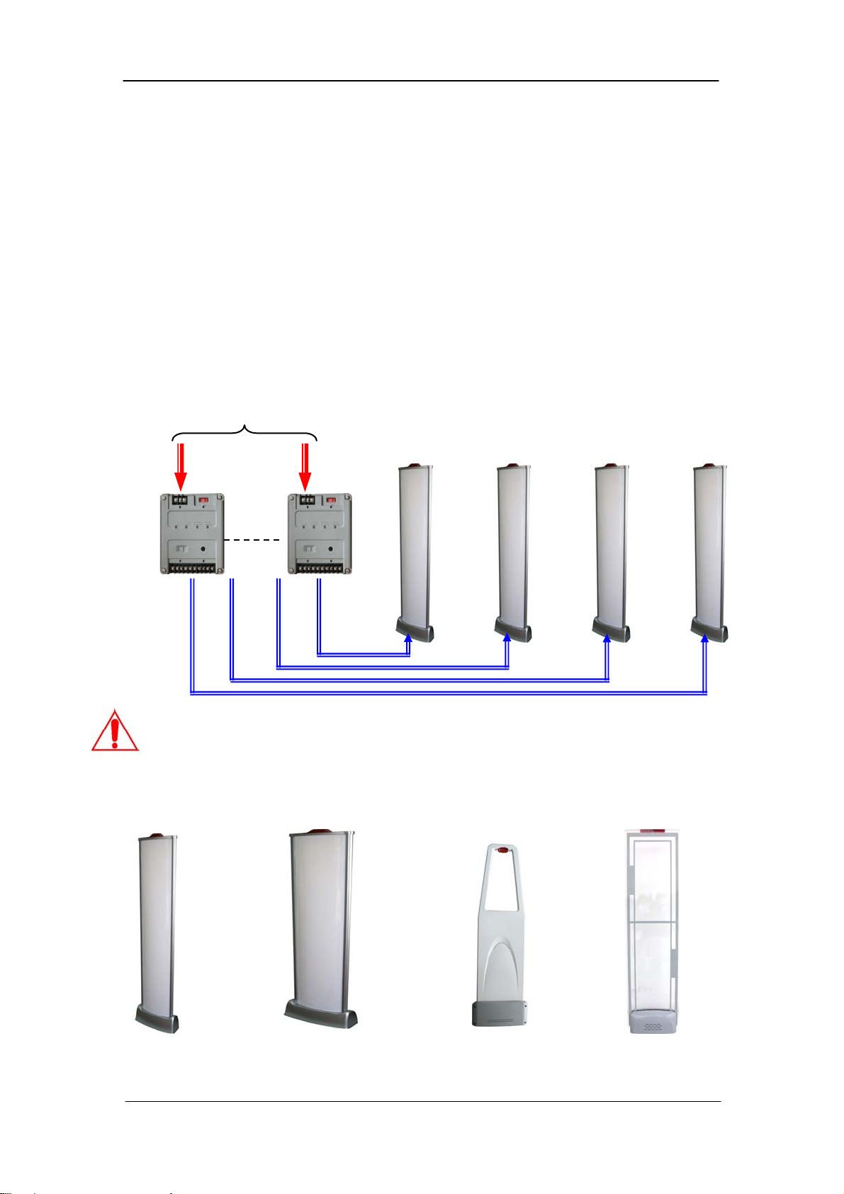
24vac power and data/control is carried by a single TX cable from the SPS to the pedestal.
Each SPS is individually powered. This picture depicts and example where 4 power supplies
are integrated into a single industry standard rack with main power input and to which each
SPS is then connected.
Caution! One SPS can only power only one transceiver pedestal.
The Common Platform Product Line includes any of the following antenna models.
AdGuard BTL
AC Input
AdGuard XL BTL
Example: AdGuard Transceiver Antennas
Pedestal A
Power & Control
Pedestal B Pedestal C Pedestal D
Premier Guard BTLLane Guard BTL
2

Common Platform EAS Systems
Product Names and Part Numbers
Accessories
Accessory Name
1. Smart Power Supply (SPS unit) WG SPS24
2. Instruction Manual
3. Power Line Connector (2 pins)
4. Communication Connector (4 pins)
5. Laptop Tuning Software
6. Serial Tuning Cable
7. USB to Serial Convertor
8. WG IR Tuning Module
Systems
Antenna Name
Order Number
Order Number
1. AdGuard BTL Transceiver Pedestal WG BTLAG
2. AdGuard BTL Slave Pedestal WG BTLAG-EX
3. AdGuard XL BTL Transceiver Pedestal WG BTLAGX
4. AdGuard XL BTL Slave Pedestal WG BTLAGX-EX
5. Lane Guard Transceiver Pedestal WG BTLLG
6. Premier Guard BTL Transceiver WG BTLPG
7. Premier Pro BTL Transceiver WG BTLPP
3

Common Platform EAS Systems
Common Platform Features & Benefits
• All-in-One platform design for the Acousto-Magnetic (AM) product line makes it a
perfect AM detection core solution for various antenna forms and needs. There are
visible advantages on short term and long term operation along with low cost
maintenance.
• Unprecedented Digital Signal Processing Technology
The common platform line brings an ever advancing DSP technology to an
unprecedented level compared with traditional anti-theft solutions, eliminating false
alarms and maintaining a considerable detection range.
• Universal Mobile PC Tuning Interface
Benefiting from its highly performance-rich digital processing controller, the common
platform can connect to laptop PC through the popular USB port.
• Anti-Jammer Alarm
The Anti-Jammer alarm function addresses the modern high-tech theft actions that
defeat the Acousto-Magnetic detection system with DIY jamming devices. WG’s
common platform design detects and alerts security personnel as soon as the jammer
device attempts to defeat the transceiver pedestal.
• Local and Remote Audible and Visual Notification
Alarm flexibility provides local alarming at the pedestal plus remote alarm notification
through the SPS via convenient visual and external ports.
• Transceivers can be individually optimized for label or ferrite tag detection.
4
 Loading...