

Page 1
= a
INSTRUCTIONS
FOR
II
WESTON
MODEL686 - TYPElOA
.True Mutual Conductance
Vacuum Tube Analyzer
II
1:1
Ii!!
II
II
II
j,
'.2551 3.54
II
WESTON ELECTRICALINSTRUMENT CORPORATION
NEWARK5, NEW JERSEY,U. S. A.
Pri"ted in U.S.A.
1
Page 2
INSTRUCTIONS
FOR
WESTON
MODEL 686 - TYPE lOA
True Mutual Conductance Vacuum
Tube Analyzer
*
CONTENTS PAGE
Controls, Variable
Control Grid Voltage AdjusteL_mmm m_umm_m4
Heater Voltage Adjusterm_uhm_mmum_m__uu__m___A
Hum mmmmm_u__u__um___m__umm 5, 7 (Step27)
Plate Voltage Adjuster:
See "D-C Power Supply Controls"mm u m_5
Screen Voltage Adjuster:
See "D-C Power Supply Controls"m_mmm__m_m5
Self- Bias Resistance
Signal Amplitude AdjusteL_m__uuuum_5, 8 (Step 29)
Suppressor Voltage Adjuster:-
See "D-C Power Supply Controls"m__m__m__mu__5
D-C Power Supply Controls_m_m_mmmmm m__5
Detailed Description of Model 686 Type 10A__3-4-5-6
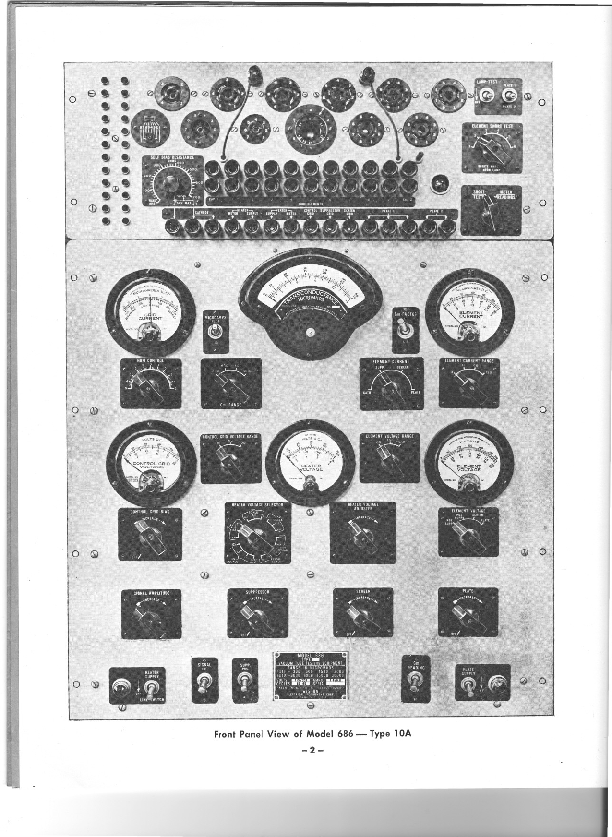
Front Panel View of Model 686 Type 10Am_mmmm__2
General Description m m___n__m_m mm_3
General Information __nm__mm__h__mum_mm_mmmm_
Gm Readings
Amplifier Tubes __hu mm___mm__u__mnm__mm_m7-8
Inconsistent on Filament Types:
See "Hum Control" _mm___mmm_mmu5, 7 (Step 27)
Low Gm Indications_muum__mumumm___m_m_hu 11
No G.mIndications_mm_m_mmmmm__mmmummuu 11
Grid Current _mmmm m_m_mm_m3, 7 (Step 28), 10
Helpful Suggestions in Tube Testinguhuum__h_uhum_1 0
Instruction Book um_mm_m__m m_m m h 10
Maintenance uhm_m m_m_m_mum_m_h__mmum
Meters
Control Grid Voltageu n__n mn_m__n nu4
Element Current _m m_m__m___m__mm m4
Element Voltage u umu__m mm 4
Gm (Mutual Conductance} m uu m___3
Grid Current __ 00__m__ um m__m ________00_3
Heater Voltage mmmmm_m_mmm m_mm__mm_h__4
Operation
Line Connections for 230 Voltsm___un__m__m_m m_6
Step-By Step Test Procedure__um__mm_un_m6-7-8-9
Theory of Operation_m_mm_m mumumm_ 9-10
00 ___ _ 00 _00 __ _ _m __ _ __ __ _ _ _ _00 __ _m___5
10
11
CONTENTS
Order of Adjustment of Element Potentiometersmmm_5
Ordering Information _u__mm__mm mmm__m__m
Precautions __u__h__mm_mm_m_h mm_mm_umm m 11
PAGE
11
Switches, Rotary
"Control Grid" (bias} mmm m_m___m_m_-4
"Heater Voltage" u__m__mm__mm_m_nnm__m_mm_mA
"Gm Ra nge" _00 0000000000
"Element Current" mm mnm__m_m_mmmm__m_m__A
"Element Current Range"m__m__mmmmmmmm_m_A
"Element Voltage" ummm_mm mm_m_m_m__mu4
"Element Voltage Rang,e" __mmmmm hum_m___mA
Switches, Toggle
"Gm Reading" __nm um m_m m__m 6
"H eater Supply" 00 0000 0000___000000
"Gm Factor" n nn ~ 3
"Lamp Test' 00 00 000000___ ___00 000000 6
"Microamperes" u__m_uum m__mm_m__umm 3
"Plate 1- Plate 2" uu__mm_mmm__mn m__um___uu5
"Plate Su pply" nu m__m m m6
"Signal Cal." 00000000 00 000000 0000 00___6
"Supp" (Pos-Neg) mmm umm umm__6
Tube Manuals m_m_mmnmm__m_m__m mmmmm
Tube Reject Limits mm mum mu m__n m___m_ 10
Tube Testing
Ampl ifiers
Converters & Mixer Oscillatorsm_mm__m_h mm__8
Diode Detectors ___mnum_m___m m m_mm8
Rectifie rs _ __ __ __ _ _ __ 00_ _ ____ _ _ __ __ _ _ ___ __ ____ __ _ _ _ ___ 00 __ _ _00 __ _ 00 8
Thyratro n s __ __ _ __ __ _ __ __ _ __ _ _ __ __ _ __ __ _ __ __ _ __ _ ___ __ __ _ __ _ - - - - - - - - - - - - 8-9
_____u__m_mu 00_m__ ___u_m__ umu_ __ ___um _6-7-8
Voltage Regulators hu__mm__mmuu nmm_mm__mn9 '
Wiring Diagram of Model 686 Type 1OAu__m_humm12
10
3
6
I
Page 3
1
Ii Ii
e. ..
o
. .
" .
., .
Ii~.
.. ..
. .
. .
o
-0
.([i.
<D..
. .
Front Panel View of Model686 - Type lOA
-2-
Page 4
INSTRUCTIONSFOR MODEL 686- TYPE lOA
TRUE MUTUAL CONDUCTANCE VACUUM TUBE ANALYZER
GENERALDESCRIPTION
The Model 686 is a complete direct reading True
Mutual Conductance Vacuum Tube Analyzer de-
signed to operate from any 105 to 125 or 230 volt
50-60 cycle outlet. It has eight mutual conductance
ranges with full scale readings of 300, 600, 1500 and
3,000 micromhos and also 3,000, 6,000, 15,000 and
30,000 micromhos. Instruments are provided for ac-
curately measuring all electrode voltages and for
reading electrode currents including minute grid
currents.
Internal power supplies and a signal source provide
all necessary potentials to panel controls, wherein
adjustments can be made in accordance with meter
readings. Tube sockets for all commercial type re-
ceiving tubes are mounted on a removable socket
panel across the top front section of the equipment.
These in turn connect through short-test switches to
patch cord jacks which are marked with R.M.A. pin
numbers and are used with patch cords for any or
all electrode connections. Thus with complete con-
nector flexibility and complete voltage control, all
kinds of static characteristics can be plotted, in addi-
tion to the measurement of Gill under any or all ap-
plied potential conditions.
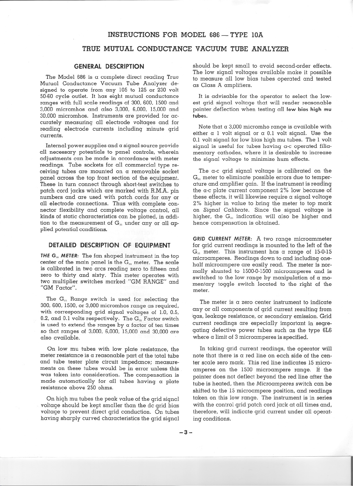
DETAILEDDESCRIPTIONOF EQUIPMENT
THEG./IIMETER:The fan shaped instrument in the top
center of the main panel is the Gillmeter. The scale
is calibrated in two arcs reading zero to fifteen and
zero to thirty and sixty. This meter operates with
two multiplier switches marked "GM RANGE" and
"GM Factor".
should be kept small to avoid second-order effects.
The low signal voltages available make it possible
to measure all low bias tubes operated and tested
as Class A amplifiers.
It is advisable for the operator to select the low-
est grid signal voltage that will render reasonable
pointer deflection when testing all low bias high mu
tubes.
Note that a 3,000 micromho range is available with
either a 1 volt signal or a 0.1 volt signal. Use the
0.1 volt signal for low bias high mu tubes. The 1 volt
signal is useful for tubes having a-c operated filia-
mentary cathodes, where it is desirable to increase
the signal voltage to minimize hum effects.
The a-c grid signal voltage is calibrated on the
Gill meter to eliminate possible errors due to temper-
ature and amplifier gain. If the instrument is reading
the a-c plate current component 2% low because of
these effects, it will likewise require a signal voltage
2% higher in value to bring the meter to top mark
on Signal Calibrate. Since the signal voltage is
higher, the GIll indication will also be higher and
hence compensation is obtained.
GRIDCURRENTMETER:A two range microammeter
for grid current readings is mounted to the left of the
Gill meter. This instrument has a range of 15-0-15
microamperes. Readings down to and including one-
half microampere are easily read. The meter is nor-
mally shunted to 1500-0-1500 microamperes and is
switched to the low range by manipulation of a mo-
mentary toggle switch located to the right of the
meter.
The Gill Range switch is used for selecting the
300,600, 1500,or 3,000 micromhos range as required,
with corresponding grid signal voltages of 1.0, 0.5,
0.2, and 0.1 volts respectively. The GIllFactor switch
is used to extend the ranges by a factor of ten times
so that ranges of 3,000, 6,000, 15,000 and 30,000 are
also available.
On low mu tubes with low plate resistance, the
meter resistance is a reasonable part of the total tube
and tube tester plate circuit impedance; measure-
ments on these tubes would be in error unless .this
was taken into consideration. The compensation is
made automatically for all tubes having a plate
resistance above 250 ohms.
On high mu tubes the peak value of the grid signal
. voltage should be kept smaller than the dc grid bias
voltage to prevent direct grid conduction. On tubes
having sharply curved characteristics the grid signal
The meter is a zero center instrument to indicate
any or all components of grid current resulting from
gas, leakage resistance, or secondary emission. Grid
current readings are especially important in segre-
gating defective power tubes such as the type 6L6
where a limit of 3 microamperes is specified.
In taking grid current readings, the operator will
note that there is a red line on each side of the cen-
ter scale zero mark. This red line indicates 15 micro-
. ,
amperes on the 1500 microampere range. If the
pointer does not deflect beyond the red line after the
tube is heated, then the Microamperes switch can be
shifted to the 15 microampere position, and readings
taken on this low range. The instrument is in series
with the control grid patch cord jack at all times and,
therefore, will indicate grid current under all operat-
ing conditions.
-3-
Page 5
I
1
j
1
1
1
!
1
!
;
.1
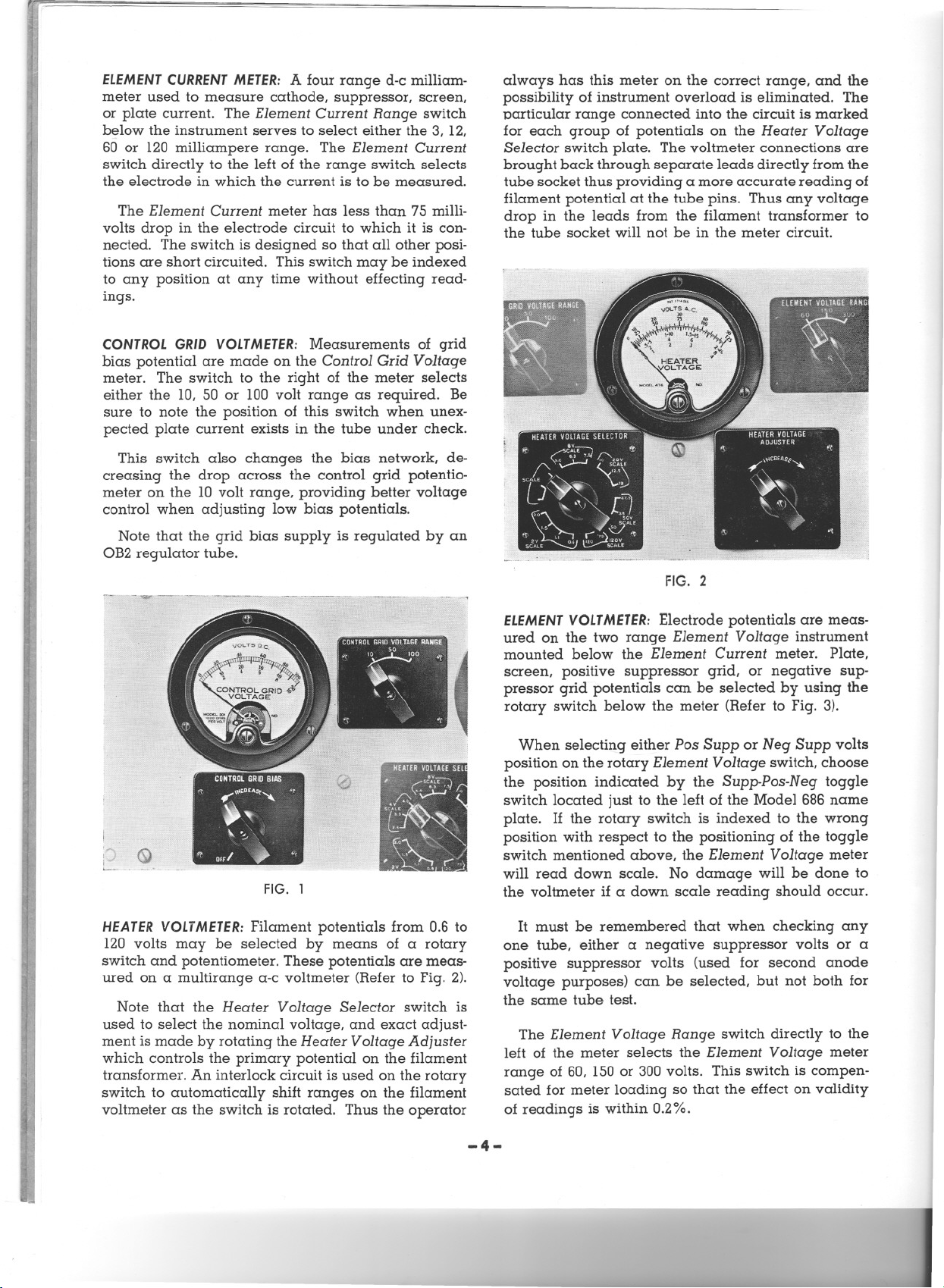
ELEMENTCURRENTMETER: A four range d-c milliam-
meter used to measure cathode, suppressor, screen,
or plate current. The Element Current Range switch
below the instrument serves to select either the 3, 12,
60 or 120 milliampere range. The Element Current
switch directly to the left of the range switch selects
the electrode in which the current is to be measured.
The Element Current meter has less than 75 milli-
volts drop in the electrode circuit to which it is con-
always has this meter on the correct range, and the
possibility of instrument overload is eliminated. The
particular range connected into the circuit is marked
for each group of potentials on the Heater Voltage
Selector switch plate. The voltmeter connections are
brought back through separate leads directly from the
tube socket thus providing a more accurate reading of
filament potential at the tube pins. Thus any voltage
drop in the leads from the filament transformer to
the tube socket will not be in the meter circuit.
nected. The switch is designed so that all other posi-
J
tions are short circuited. This switch may be indexed
to any position at any time without effecting read-
ings.
CONTROLGRIDVOLTMETER:
Measurements of grid
bias potential are made on the Control Grid Voltage
meter. The switch to the right of the meter selects
either the 10, 50 or 100 volt range as required. Be
sure to note the position of this switch when unex-
pected plate current exists in the tube under check.
This switch also changes the bias network, de-
creasing the drop across the control grid potentio-
meter on the 10 volt range, providing better voltage
control when adjusting low bias potentials.
Note that the grid bias supply is regulated by an
OB2 regulator tube.
I
L
FIG. 1
FIG. 2
ELEMENTVOLTMETER:
Electrode potentials are meas-
ured on the two range Element Voltage instrument
mounted below the Element Current meter. Plate,
screen, positive suppressor grid, or negative sup-
pressor grid potentials can be selected by using the
rotary switch below the meter (Refer to Fig. 3).
When selecting either Pos Supp or Neg Supp volts
position on the rotary Element Voltage switch, choose
the position indicated by the Supp-Pos-N eg toggle
switch located just to the left of the Model 686 name
plate. If the rotary switch is indexed to the wrong
position with respect to the positioning of the toggle
switch mentioned above, the Element Voltage meter
will read down scale. No damage will be done to
the voltmeter if a down scale reading should occur.
HEATERVOLTMETER:Filament potentials from 0.6 to
120 volts may be selected by means of a rotary
switch and potentiometer. These potentials are meas-
ured on a multirange a-c voltmeter (Refer to Fig. 2).
Note that the Heater Voltage Selector switch is
used to select the nominal voltage, and exact adjust-
ment is made by rotating the Heater Voltage Adjuster
i
,
1
which controls the primary potential on the filament
transformer. An interlock circuit is used on the rotary
switch to automatically shift ranges on the filament
voltmeter as the switch is rotated. Thus the operator
i~
i
j
1
4
~1
-4-
It must be remembered that when checking any
one tube, either a negative suppressor volts or a
positive suppressor volts (used for second anode
voltage purposes) can be selected, but not both for
the same tube test.
The Element Voltage Range switch directly to the
left of the meter selects the Element Voltage meter
range of 60, 150 or 300 volts. This switch is compen-
sated for meter loading so that the effect on validity
of readings is within 0.2%.
- ------
Page 6

FIG. 3
D-CPOWERSUPPLYCONTROLS:Individual suppressor
grid, screen grid, and plate adjusters are mounted
in line across the lower section of the Model 686
panel. These are 150 watt or 100 watt vitreous type
potentiometers connected in the d-c supply circuit.
These high wattage ratings are used to provide a
long peripheral length of contact travel, thus giving
accurate potential settings on the tube electrodes. The
element voltages should be adjusted in the following
order to prevent damage to the screen and cathode
due to excessive currents: (1) control grid (2) plate
(3) screen. All electrode potentials can then be re-
adjusted and any changes due to tube loading of
the power supply can be corrected. The accuracy
of the mutual conductance readings depend to a
great extent on the accuracy of these electrode poten-
tial adjustments.
SIGNALAMPLITUDEADJUSTER:
ing the signal voltage this potentiometer is used to
compensate for different line voltages. The signal
voltage is checked at full scale on the Gillmeter and
any necessary correction is then made with this
control.
To correct for different line voltages the Signal
switch should be placed on the "Ca1." position and
the Signal Amplitude Adjuster rotated to obtain full
scale deflection on the Gm meter.
HUM CONTROL:
accurate electrical center tap on the filament for
correct Gm readings, and it is the purpose of this
control to provide such an adjustment. On heater
voltage switch positions 12.5 volts and above, the
Hum Control is disconnected to prevent excessive
heat dissipation.
After the tube is in position and all electrode
potentials have been adjusted to the specified val-
ues, the GillFactor toggle switch to the right of the
Gillmeter should be set to the "x 1" position and the
Hum Control set for a minimum or zero reading on
Filamentary tube types require an
By effectively chang-
the Gill meter. (Serious errors in mutual conductance
readings can be expected if this operation is not per-
formed carefullyJ
SELFBIAS RESISTANCECONTROL:The Model 686 is
equipped with a Self Bias Resistance control mounted
on the left side of the top panel section. This control
provides for checking certain tube types such as the
6I4, 6I6 and 1231 where self bias is definitely speci-
fied by the manufacturer. These tubes tend to draw
grid current or are unstable under equivalent fixed
bias conditions, thus causing errors in Gmreadings.
The control may be varied from 0 to 700 ohms,
and to prevent degeneration the unit is by-passed
by a 1,000 m.f., 50 volt condenser. When checking
the normal fixed bias types this control must be set
to zero (0) but on those types requiring self bias the
Control Grid Voltage Adjuster must be set in the
most counter-clockwise position. This procedure is
necessary to prevent fixed bias from being applied
in addition to the self bias.
To prevent damage to the 1,000 microfarad con-
denser, a simple calculation should be made to see
that the product of the expected cathode current,
and the resistance in the self bias circuit does not
exceed 50 volts: V == 1x R x .001
Where V == Voltage appearing across 1,000
microfarad condenser.
I == Expected cathode current in mill-
amperes.
R ==Resistance selected by Self Bias
switch position.
SHORTTEST-METERREADINGAND ELEMENTSHORT
TESTSWITCHES:
Element Short Test switches mounted on the right
side of the top panel section provide the necessary
means for short checking tubes with a d-c potential.
Tubes, having a filament or heater, may be short
checked, either hot or cold. The Short Test-Meter
Reading switch disconnects the d-c potential and
meters from the tube elements and connects a small
d-c power supply and a neon lamp into a group of
circuits controlled by the Element Short Test switch.
This switch segregates the element to be short
checked, leaving all the other elements tied together.
The filament or heaters should be at normal op-
erating temperature when hot short checking, and
the Short Test-Meter Reading switch should be in-
dexed to "Short Test" position. The Element Short
Test switch is then rotated through its six positions,
stopping at each position to tap the tube.
If the patch cords have been connected so as to
use both PI = Plate 1 and Pz = Plate 2, index the
Plate 1
right top panel section to its other position and rotate
the Element Short Test switch through its six positions
again. A slight flicker of the neon lamp between
positions on the Element Short Test switch does not
indicate a short in the tube.
- Plate 2 toggle switch located on the upper
The Short Test-Meter Reading and
-5-
Page 7

p
HEATERSUPPLYTOGGLESWITCH:Located at the bot-
tom left side of the panel with its associated green
jewel pilot lamp, this toggle switch disconnects the
device completely from the line supply when in-
dexed to the "Off" position. When in the "On" posi-
tion, the heater transformer is energized and the line
supply voltage is delivered to the Plate Supply
Toggle Switch. After making the heater connections,
the tube can be warming up while the operator is
completing the patching operation by indexing the
Heater Supply toggle switch to the "On" position.
The "Plate Supply" toggle is shorted out on 230 volt
service, therefore, use the "Line Switch" as the "On-
Off" switch for the entire device.
PLATESUPPLYTOGGLESWITCH:
all of the internal d-c power sources and is inopera-
tive if the Heater Supply toggle is in the "Off" posi-
tion. The Plate Supply toggle should always be in
the "Off" position when the operator is changing or
removing patch cords.
SIGNALCALIBRATETOGGLESWITCH:To the right of
the Heater Supply toggle is a momentary type Signal
CaI. toggle switch. A change in power line voltage,
of course, will affect the grid signal and hence it
becomes necessary to check this potential just before
taking Gmreadings. Indexing the Signal Cal. toggle
to the "CaI." position places the grid signal directly
across the Gill meter. Regardless of Gm range se-
lected, the Gm meter must indicate top mark on this
test. If it does not, the Signal Amplitude Adjuster
should be rotated until top mark is obtained.
Gill READING TOGGLESWITCH: This switch is located
to the left of the Plate Supply switch and is of the
momentary type. It is used to apply the signal volt-
age when the operator is ready to take a Gm read-
ing.
SUPPRESSORPOSNEGTOGGLESWITCH:The
of this toggle is to allow the operator to select either
a negative potential for suppressor, or a positive
potential for tubes requiring a second anode voltage
such as the oscillator plate in a penta grid converter.
It must be kept in mind that while checking a given
tube only one or the other potential may be used.
No occasion will arise requiring both a negative
suppressor potential and a second anode positive
potential, because in such cases, the suppressor of
the tube is always connected directly to cathode.
To obtain negative suppressor volts index this
toggle, located just to the left of the name plate at
the bottom of the panel, to the NEG position. To
measure the negative potential rotate the Element
Volts switch to the "Neg Supp" position.
LAMPTESTTOGGLESWITCH:
rotary Plate I - Plate 2 switch, this toggle provides
a ready means for checking the neon lamp. If a
tube shows no short and there is some doubt as to
This switch operates
purpose
Located to the left of the
the condition of the neon lamp, lift the toggle to its
upper position and if it does not glow replace with
a new lamp.
OPERATION
STEP-BY-STEPTESTINGPROCEDURE
GENERAL:Read the paper tag on the f!ont panel of
the instrument. Remove the back cover and insert
the 5U4-G rectifier in the octal socket. Ascertain
whether the 3A4 tube is in place by removing the
shield from the miniature socket. Check to see that
the proper miniature tubes are in their respective
shielded sockets. Screw the neon lamp in the socket
located above the Lamp Test toggle switch. The line
cord can then be brought to the outside of the case
and the back cover replaced.
A toggle switch has been incorporated to facilitate
change over from 115 volt to 230 volt a-c operation.
This switch is located on the shelf jnside the device
between the 8 mfd. condenser and the small signal-
short check transformer.
The toggle is normally set for 115 volt operation.
For 230 volt operation set the switch as indicated
by adjacent markings.
The Plate
service, therefore, use the "Line Switch" as the "On-
Off" switch for the entire device.
The instrument is now ready for use and the
Step-by-Step Procedure outlined below should be
read carefully before attempting to check any tubes.
It is suggested that a type 6C4 or any indirectly
heated triode be used to acquaint the operator of
this device with the various controls and their
functions.
AMPLIFIERTUBES:
1. Plug the line cord into a power source having
a frequency of 50-60 cycles and voltage betwee.n
105-125.. Refer to preceding paragraph for 230 volt
lines.
2. Place Heater Supply and Plate Supply toggle
switches in "Off" position.
3. Patch the jumper leads in accordance with the
tube base diagram of the tube to be checked follow-
ing the specific procedures for Cathode, Heater and
Suppressor connections as follows:
A-CATHODE
I-Connect cathode of the tube to any of the
II-Connect the tube cathode to the second or
Supply toggle is shorted out on 230volt
three Cathode jacks in the bottom row when
the Self Bias Resistance control is set to
"Fixed Bias."
third Cathode jack if Self Bias Resistance
control is set to any value above zero ohms.
-6-
Page 8

B-HEATERS
I-Connect the heater or filament of the tube
to the Heater Supply jacks.
II-Duplicate the connections from the heater of
lhe tube and connect to the Heater Meter
jacks.
C-SUPPRESSOR
I-Connect suppressor to Suppressor Grid jack
except for the following two conditions.
(a) When other tube elements require a pos-
itive voltage from the Suppressor Grid
jack follow steps II or III outlined below.
(b) When Self Bias Resistance control is set
to or any value above zero ohms, step
III outlined below must be followed.
II-Connect suppressor of tube to any of the
three Cathode jacks in the bottom row when
the Self Bias Resistance control is set to
"Fixed Bias" or zero ohms.
III-Connect suppressor of tube to the second or
third Cathode jack when the Self Bias Resist-
ance control to set to any value above zero
ohms.
4. Rotate Short Test
-Meter Reading switch to
"Short Test" position.
5. Select the required heater voltage by setting the
Heater Voltage Selector switch.
6. Insert tube in a socket corresponding to the pin
arrangement of the tube to be checked.
7. Place the Heater Supply toggle in the "On"
position. For those instruments connected for 230
volt line service see "Note" under paragraph headed
"HEATER SUPPLY TOGGLE SWITCH", on page 6.
8. Rotate Heater Voltage Adjuster to correct heater
voltage indicated on Heater Voltage meter.
. 9. Rotate Element Short Test switch through its six
positions, stopping at each position to tap the tube.
10. A lighted neon lamp indicates a short in the
tube and no further tests should be conducted. A
lighted neon lamp on Position (1) indicates heater to
cathode leakage.
11. From time to time check neon lamp by placing
Lamp Test toggle in the upper position.
12. Set the Self Bias Resistance control to "Fixed
Bias" or zero ohms position. Note: If manufacturer's
rating specifically calls for self bias, set the control
to the proper value.
13. Rotate the Control Grid, Suppressor, Screen
and Plate adjusters to the extreme counter-clockwise
position.
14. Index Short Test -Meter Reading switch to
"Meter Reading" position.
IS. Place Plate Supply toggle switch in the "On"
position.
.
16. Index Gill Factor switch to the "XIO" position.
The "Xl" position may be used for subminiature
tubes or low bias high mu tubes.
17. Index
with the expected mutual conductance. This is the
value listed by the manufacturer.
18. Index Element Current switch located below
the
Gill Factor toggle switch to the "Plate" position.
19. Index Element Current Range switch located
below the Element Current meter to a position higher
than the expected plate current specified by manu-
facturer.
20. Rotate the Control Grid VoItage Adjuster un-
til the Control Grid Voltmeter indicates the value
specified by manufacturer. If over 10 volts, index
Control Grid switch to "50 Volts" position. Rotate to
extreme counter-clockwise position if Self Bias Re-
sistance control is set to any position other than
"Fixed Bias" or zero ohms.
21. Index the Element Voltage switch located un-
der the Element Voltage meter to the "Plate" position.
22. Advance the Plate Voltage Adjuster until the
Element Voltage meter indicates the plate potential
specified by manufacturer. If over 150 volts, index
Element Voltage Range switch to "300" volts position.
23. Index Element Voltage switch to "Screen" posi-
tion.
24. Advance Screen Grid Voltage Adjuster until
the Element Voltage meter indicates. the screen po-
tential specified by manufacturer. If over 150 volts,
index Element Voltage Range switch to "300" volts
position. Important Note: To prevent excessive screen
dissipation keep the plate potential the same as or
higher than the screen potential.
25. Recheck the plate, screen and control grid
voltages.
26. Plate, screen, suppressor or cathode currents
can be readily checked by rotating the Element
Current switch through its four positions noting the
current on the Element Current meter. It may be
necessary in doing this to change range on the Ele-
ment Current meter by rotating the Element Current
Range switch to one of the other positions.
27. If the tube is a filiamentary type, place the
Gill Factor toggle switch to the "x 1" position and
rotate the Hum Control to give minimum reading on
the fan-shaped Micromhos meter. Note: Serious errors
in mutual conductance readings can be expected if
this operation is not performed carefully on filament
types.
28. Pull the Microamperes toggle switch to the
"IS" position. Read microampere grid current di-
rectly on 15 scale. Refer to "Grid Current" under
Helpful Suggestions In Tube Testing on page 10.
Gill Range switch to .a range consistent
-7-
Page 9

29. Lift the Signal toggle switch to the "Cal." posi-
tion and rotate the Signal Amplitude Adjuster to
bring the Micromhos meter to exactly top mark.
30. Release Signal toggle switch.
31. To take the Gm reading, index the "Gill" tog-
gle switch to the "Reading" position and read the
Micromhos meter. Read the scale which corresponds
to the "GmRange" switch setting and multiply by an
added factor of 10 if the "Gm Factor" switch is set to
the "XI0" position.
CONVERTERAND MIXER-OSCILLATOR TYPES:
47. Patch the jumper leads in accordance with the
information in Tube Data Chart supplied separately.
A-The figure in parenthesis in the Tube Data
Charts refers to the pin connection. Example:
A type lA7-GT shows the figure (3) and (6)in
parenthesis in the column headed Plate Volts.
Hence pins 3 and 6 are connected together
and patched to the Plate 1 jack by means of
the jumper leads.
RECTIFIERTUBES:
32. Patch jumper leads as in steps "3 and 3-(B)."
If rectifier has double plates, patch one of the plates
to the Plate 1 jack and the other to Plate 2 jack.
33. Follow steps 4-10 inclusive. If double rectifier
plates have been patched as above, short check the
tube as in step 9 indexing the Plate toggle switch to
both "Plate I" and "Plate 2" positions.
34. Follow steps 12-15 inclusive.
35. Set G.mFactor switch to "xl0."
36. Turn "Signal Amplitude" adjuster to zero. Note:
If steps 35 and 36 are not followed, the emission
measurements will not be in error. However, follow-
ing these two steps reduces the Gm meter sensitivity.
37. Index Element Current switch to "Plate" posi-
tion.
38. Index Element Current Range switch to "120"
position.
39. Index Element Volts switch to "60."
40. Place Plate Supply toggle switch in the "On"
position.
41. Advance the Plate Voltage Adjuster carefully
until the Element Current meter indicates the current
listed in the Tube Data Chart suppli~d separately.
42. Reject the tube as bad if the plate voltage re-
quired to give the specified current is greater than
that shown in the Tube Data Chart su,Pplied sep-
arately.
43. Repeat the emission check on the second plate
in the same manner indexing the Plate 1- Plate 2
toggle to its other position.
44. If the two plates have materially different emis-
sion readings the tube should be rejected.
DIODEDETECTORS:
45. Patch jumpers as in step 32 and in addition
connect all other elements to cathode.
46. Follow steps 33-44 inclusive, except that in
step 38 the Element Current Range switch should be
indexed to the "3" position. Note: The 0.8 MA. limit at
10 volts maximum is usually considered satisfactory,
however, diodes normally pass considerably greater
current, some going as high as 2 or 3 MA.
B-The letter (C) in parenthesis denotes Grid Cap.
Example: A type lA7-GT shows the figure (5)
and the letter (C) in parenthesis in the column
headed Control Grid VoHs. Hence pin 5 and
the tube's grid cap are connected together and
patched to the Control Grid jack by means of
the jumper leads.
48. Follow steps 4 through 31 omitting any re-
marks concerning "manufacturer's specifications"
and substituting "value specified in the Tube Data
Chart supplied separately.
49. Reject tube when the mutual conductance indi-
cation is below that value specified in the column
headed "Life End."
THYRATRONTUBES:
Thyratrons such as the 2050 and 2051 can be
checked in any type Model 686. The step-by-step
procedure given below is for the tube type 2050.
Checking other thyratrons involves the same pro-
cedure but it must be kept in mind that the tubes
should be of a type similar to the 2050 and 2051.
1. Make connections by use of patch cords in
accordance with the base diagram except that
a 100,000 ohm 1/2 watt resistor should be in-
serted in the grid lead to pin 5. Number 2 grid
should be connected directly to cathode.
2. Set G./IIFactor switch to "x 10".
3. Turn Signal Amplitude Adjuster to zero.
4. Set Element Current Range switch to "120" milli-
amperes.
5. Set Element Current switch to "Plate" posi-
tion.
6. Before inserting the tube apply the following
element voltages:
. .
Filament _ _ _ ____ __ ___ __ ____ __ _. 6.3
Control Grid m___m m_. - 10 volts d-c
Platem_m m m + 212 volts d-c
7. Insert tube, readjust filament voltage and allow
to heat for at least 30 seconds.
8. Reduce the grid bias carefully until the thyra-
tron fires. .
-8-
--
Page 10

9. LIMITS: If the tube fires between - 3 and - 1
volts on the grid, the tube is within manufac-
turing limits for both end point and variation
in new tubes.
Note: Once the tube fires, the grid loses control.
If it should be necessary to repeat the test, in-
crease the grid bias to
the plate voltage to zero, and then reset it to
212 volts and repeat the above procedure.
The plate current for tubes 2050 and 2051
should not exceed 100 milliamperes and 75
milliamperes respectively. If it does, reduce
the plate voltage slightly to bring it within these
values.
Note also that when the thyratron fires the
plate voltage will drop to about 7-1/2 volts.
This is normal.
For low current thyratrons, a lower initial
plate voltage should be used, or a current lim-
iting resistor inserted in the plate patch cord
lead.
VOLTAGE REGULATORS:
The Model 686 can check voltage regulator tubes
similar to the 874 and VR-150-30 types. The pro-
cedure outlined below is for checking the 874 type.
1. Make connections by use of patch cords in
accordance with the base diagram. In the case
of the 874, Pin 1 is the cathode and Pin 3 is
the anode or plate.
2. Set Gm Factor switch to "x 10".
3. Turn "Signal Amplitude" control down to zero.
4. Set Element Current Range switch to "120" milli-
amperes.
5. Set Element Current switch to "Plate" posi-
tion.
6. Increase the plate voltage until conduction be-
gins. This should be at approximately 115 volts
for the type 874. (For other voltage regulators
refer to manufacturer's ratings).
7. To check the regulating characteristics vary
the plate voltage to produce anode currents be-
tween 10 and 50 milliamperes maximum. (For
other voltage regulators see manufacturer's
ratings.)
Note: The voltage applied to produce currents
between 10 and 50 milliamperes should be
within the limits indicated by the man ufac-
turer's ratings. In the case of the 874 the voltage
after conduction should not vary more than 7
when the current is varied from 10 to 50 milli-
amperes.
- 10 volts and decrease
THEORYOF OPERATION
Essentially the Model 686 is a low impedance
power supply metered for potentials and currents
and provided with a means of introducing an a-c
signal into the grid bias line and measuring the a-c
component in the plate circuit.
The incoming a-c line energizes the d-c power
supply, the heater voltage supply and the a-c grid
signal transformer. The filament transformer control
is located in the primary leads thus providing proper
adjustment to take care of varying line voltage con-
ditions. A rotary switch selects secondary taps to
give the necessary heater voltages for all tubes.
The d-c power supply delivers potentials to the
plate, screen and suppressor controls. Following
these controls the potentials are metered and the cir-
cuit is so arranged that the element milliammeter
can be placed in each of the lines. A separate reg-
ulated power supply develops the voltage for grid
bias. This potential is likewise controlled by a poten-
tiometer. A separate voltmeter is used to measure
this potential and a microammeter is placed in the
circuit to detect the presence of grid current.
The a-c grid signal winding together with a signal
voltage divider is placed in series with the control
grid circuit to the tube. The proper signal voltages
are selected by the Gm Range switch which is con-
nected to the signal voltage divider. The injection
of the a-c grid signal into the grid bias circuit is a
function performed by the GmReading toggle switch.
The Gm meter is an amplifier-rectifier type a-c
instrument which is connected to the plate circuit for
measuring the a-c component of plate current.
The element potentials are fed to a multi-circuit
Short Test-Meter Reading switch. This switch pro-
vides the necessary circuit connections so that tube
elements may be either short checked by means of
the Element Short Test switch or energized by the
potentials from the power supply.
The a-c grid signal transformer has a separate
winding feeding a type 3A4 tube which supplies the
necessary d-c voltage for high sensitivity short check.
The Hum Control is simply a potentiometer placed
across the filament winding to provide the necessary
balance on the filament return when checking these
types. This is to prevent an additional signal (which
may either add to or subtract from the true grid sig-
nal) from appearing in the grid circuit causing a
modification in the a-c plate current component. The
Hurn Control is switched out of the circuit on heater
voltages above 10.
In checking a tube, the d-c potentials are applied
to the tube through the various controls. The a-c grid
signal is applied in series with the grid bias voltage,
and is measured by switching the Gm meter to "Sig-
nal Cal." and held to a fixed value by rotating the
Signal Amplitude Adjuster. To measure a-c compo-
-9-
Page 11

nent of plate current, the Gill meter is switched to
the "Gm Reading" position. Inasmuch as the value
of the grid signal and the a-c component of plate
current are known, the mutual conductance is the
If it is not known what reduction in Gm'is allow-
able, the limits in percent of normal listed below are
suggested as the proper end points for use in gen-
eral electronic equipment:
ratio of the two. Since the ratio 2~: == G1l1 consists
of one known value and one measured quantity, the
scale can be calibrated directly in micromhos.
GENERALINFORMATION
INSTRUCTIONBOOK: This edition of the instruction
book applies to Model 686, Type lOA.
Any questions concerning a special application,
the use, maintenance or repair of these models
should be addressed to Weston Electrical Instrument
Corporation, giving all the information listed on page
11 under paragraph ORDERING INFORMATION.
TUBE
MANUALS: It is advisable for the operator of
this device to have at his disposal a tube manual
which can be obtained from any of the tube manu-
facturers. A manual facilitates the measurements of
tubes at potentials not normally listed in the manu-
facturer's specifications.
For example, if the mutual conductance of the 6C8
were to be measured at 150 volts and -I ¥2 volts
bias a glance at the Ep-Ip curves would show that
on the vertical line corresponding to 150 volts a
change in plate current of 1.6 milliamperes would
result with a grid bias change of -1 to -2 volts.
The expected mutual conductance, therefore would
be approximately 1600 micromhos, this value being
obtained by dividing plate current change in milliam-
peres by the grid bias change in volts and multiply-
ing by 1,000. Computing the approximate Gm to be
expected as explained above sometimes eliminates
an incorrect reading due to improper testing of the
tube.
TUBE
DATA CHARTS:Tube Data Charts, supplied sep-
arately, list the manufacturer's nominal ratings for
the element potentials, mutual conductance, ampli-
fication factor, and the tube base diagram number.
These charts will in most cases handle all of the tubes
that will be checked, and should be used as a quick
reference supplement to the tube manual. Tubes not
listed in the charts can be checked if the basing and
element potentials of the tube are known.
REJECTLIMITS:
sidered as nominal limits only. It is possible that in
certain special applications it will be necessary to
reject a tube when its G1l1has fallen to possibly only
75 or 80% of its nominal value. In other cases a
reduction of 60% in the G1l1would have no adverse
effect on the operation of the circuit. If an end point
figure or an end point range is specified by the
tube manufacturer, the operator should be guided
accordingly.
The reject limits listed should be con-
RF, IF, and Pentode Voltage Amplifiers 65%
General Purpose and high mu Triodesm___50%
Power Output Types m m 50%
Converters and Mixers
(Refer to Tube Data Chart)
Rectifiers (Refer to Tube Data Chart)
Diode Detectors (Refer to page 8, Step 46.)
D-CFILAMENTSUPPLY:In certain applications it may
be desirable to measure the mutual conductance of
a filamentary type using d-c voltage instead of an
a-c source to energize the filmaent. In such cases
index the Heater Voltage switch to zero position, run
jumper leads from the d-c filament supply source to
the proper numbered pin jacks in the top two rows.
Connect an additional lead from the negative fila-
ment supply to the second or third Cathode pin jack.
A separate d-c instrument will be required to meas-
ure the filament voltage and should be connected
into the two pin jacks in the top two rows corre-
sponding to the filament connections.
HELPFULSUGGESTIONSIN TUBE TESTING
GRIDCURRENT:
be exercised to see that the grid current in micro-
amperes indicated on the Grid Current meter does
not exceed three to four microamperes. This value
changes somewhat between tube types, but the
above value can be assumed in general, to be
satisfactory. Excessive grid current will cause an
error in the Gill readings and it is advisable that a
limit of 4 microampere3 be strictly adhered to and
that some means of eliminating this condition should
be tried as outlined below.
If the Grid Current meter deflects to the left of
zero the tube is either gassy or the element potentials
applied are not correct. Check the manufacturer's
specification and note whether the proper potentials
have been applied. If the potentials are correct and
the meter indicates 4 microamperes or more to the
left of zero the tube should be rejected.
If the Grid Current meter indicates to the right of
the zero with the correct potentials applied, the tube
is oscillating. This condition must be eliminated be-
fore accurate Gillindications can be obtained. Usually
a 15 to 20 ohm resistor placed in some one of the
electrode leads, except filament or cathode, will
eliminate the tendency to oscillate.
There are some tubes requiring low bias and if the
signal voltage applied is too high, grid rectification
will cause the Grid Current meter to indicate to the
right of zero. This condition can be readily detected
by noting the increase in Grid Current meter deflec-
In using the Model 686 care should
-10-
---
Page 12

tion when the Grid Signal toggle switch is indexed
to the "On" position and the Microamperes toggle
switch is indexed to the "IS" position. To correct
this select the next higher Gm range, as this will
reduce the grid signal.
Any attempt to check certain tubes under Fixed
Bias conditions that should be checked under Self-
Bias conditions, usually results in tube oscillation
or instability.
The Grid Current meter will also indicate to the
right of zero when the plate supply and grid bias
potentials are extremely low or zero.
INCONSISTENTG.mREADINGSON fiLAMENTARYTYPE
TUBES:
tubes is caused by improper setting of the Hum Con-
trol. It is recommended that Step 7:7 in the Step-
by-Step Procedure on page 7 be performed more
carefully. The operator might find it helpful to tem-
porarily set the G.mFactor range switch to the Xl
position to obtain the maximum sensitivity when
performing this operation.
VERYLOWORNO G.mREADING:
trode potentials to be correctly applied and adjusted
the operator may find that the Gm reading is zero.
This may be caused by having the"Signal Ampli-
tude" adjuster turned down to zero.
higher than zero ohms and the grid bias voltmeter
control has not been returned to the extreme counter-
clockwise position, the total grid bias applied to the
tube will be that indicated by the Control Grid Volt-
meter plus the bias developed in the self bias resis-
tor. This condition would cause the plate current to
be very low and the Gmto be either very low or zero.
scribed in the section on Maintenance.
Inconsistent Gmreadings on filamentary type
Assuming the elec-
If the Self Bias Resistance control is set a value
Other factors causing low Gm readings are de-
Don't Fail to Bring Up the Grid Voltage First, the
Plate Voltage Second and the Screen Voltage
Third, otherwise the cathode or the screen may
be damaged.
Don't fail to completely Shut Off the device when
testing is completed.
MAINTENANCE
RECTifiERTUBES:
components in the device be checked at two year
intervals so that the equipment is maintained in a
completely satisfactory operating condition.
If the power supply will not deliver 300 volts at
100 milliamperes at a measured line voltage of 120,
the 5U4-G rectifier is failing and should be replaced.
A 6L6 or a type 2A3 tube may be used as a load by
applying 300 volts to the plate and lowering the grid
bias from the specified value until the element cur-
rent meter indicates 100 milliamperes. This will pro-
vide a convenient load for the power supply for
checking the rectifier.
Each of the small miniature type tubes, 3A4, OB2,
and 6X4, can be checked by removing it from its
socket and testing in the Model 686.
ELECTROLYTiC CONDENSERS:
years the electrolytic condensers in the Model 686
should be checked with a capacity analyzer to deter-
mine whether they are in a satisfactory condition. It
is necessary to remove the back cover to check these
condensers.
The low voltage 1,000 microfarad condenser is
located in a clip near the right hand section of
the top panel when looking at the instrument from
the back. The capacitance of this unit should not be
allowed to fall below 500 microfarads as it will
cause Gm indications to be very low under self bias
conditions.
Itis recommended that the several
.
Every two to three
PRECAUTIONS
Don't Attempt to Test a tube unless it has been found
cleared in the short test.
Don't attempt to patch the circuit unless the Plate
Supply toggle switch is in the "Off" position.
Don't Insert a Tube until you are certain that the
Heater Voltage switch is set to the correct value
for that tube. Check with the Tube Data Chart.
Don't Insert a Tube in the Test Circuit Unless All Volt-
age Adjusters Are Rotated to the "Off" Position.
This may be waived if testing a group of identical
tubes.
Don't Test Rectifiers beyond their maximum current
carrying capacity.
Don't apply more than 10 volts to diode detectors or
their emission may be lost.
The 40 microfarad 450 W.V. electrolytic conden-
sers located in clips under the shelf at the left side
when looking at the back of the instrument, should
not be allowed to fall to a value below 30 micro-
farads, nor have a power factor exceeding 30 percent.
High Gm indications can be expected on tubes
when the capacity of the 40 microfarad condensers
fall below 30 microfarads.
ORDERING INFORMATION
If an occasion should ever arise requiring the
ordering of parts, be sure to give the Model Num-
ber, Type Number, Serial Number, Voltage and Fre-
quency Ratings.
A description and location of the part in the
equipment should be as complete as possible.
Address all inquiries to Weston Electrical Instru-
ment Gorporation, 614 Frelinghuysen Avenue, New-
ark 5, New Jersey.
-11-
Page 13

!J
CAP2
~
OV
I
E
ov
Gm READING
I.OV
.
.
25 ~.5V
.
15 :
2V ~~
~ O~
5 ~ 0 Wl_ 0
.IV 00:00
Lj
5
1.500
ON!
OFF.
~
I
I
I
: 600
~ON
CALIBRATE
~
L...O OFF
PLATE2
O)--(d
:0:
PLATE J
.!~,t~__
150
:. ...
5J oXI
:. Gm FAC
45~ ~
l' ...10:
OR--
Jf
~
o ~!!!
XIO 90 .0 ~?{
~
6
~
000
2MFO'
'0
~
.0)6
SCREEN
6) (0) (d
'0
~
.0)5
SUPPRESSOR
r-HEATER METER~
GRID , ,HEATER S~PLY, f
6J ~ '-~ (OJ--'to
~---~---~-------------
~ 0000
o 0 0 _
~ 0---0 3 0 3278
-6
~
~~ I 1229
.3MEG.
.3MEG.
.3MEG
1&1
2100 27.000 ~
.u. ELEMENT o1:L...
~ 10~10 0-=-
~
o ___Q ~_;'
~
1.~ RANGEd.~.~~~:E_ 2,000 9. . 0~,~ :
'0
~
.0)3
!,THOD~ 1,000 MFD
O)-{Q~~
r------
0000
o -
o
o ~
:00 o!:L,c
: 3~ ·
I ~
ISO 21
300v-L-.,60 0.2& .
.
:j
VOLTAGE olQ ;
RANGE ~ .
50 ~
o GRID 0=
VOLTAGEGRID 0.22
U9~ffi~
SELF BIAS
RH
~
~
~
EO\AT 750
METER SHORT
Ui
READING TESTS
6.3
CAP I
~
OV
'--I
f
ADJUSTER
HEATER
VOLTAGE
ADJUSTER
t
HUM
200
Page 14

'0Ji
t:OV
l
lloIV
OV
00
o
IV
0'
r'~
O~O
000
ELEMENT
CURIIENT
o
+
..6MA
100 OHMS
--- ~ J,----
-
~+-
O~On
. 0000
-.-
60 12
120~3
ELEMENT
CURRENT
/
RANGE
-
~
I
ov !
.
.
25 S.5V
ON SCREEN f16~
Gm READING1 PLAT~~~~
J.OV OF~ VOLTAGE
F'_ J
It r25MFD.
.1MEG.t
II
)ON
CALIBRATE
,27MEG. 25,000
r-~
~ 10.OOO~
.IMEG.
~
I GRIDCURRENT
RANGE
150
5
...d-
-r_ 40MFD.
ELEMENT
L.f--
--- -- --- --- ---,
2,500
.1:
MEG
-:L 40
~ MFD.
.3MEG
.3MEG.
.3MEG.
000
1229
O~
O~<
':f',.t' 0
'(:00
4g~~I~~
b~
2J~ b ~ .
HEATER
VOLTAGE
4 230V
SELECTO&
115
#-
~
012-'
o!L-:
o!L-:
~'
~
~
10 .
0-:-=--
~
OV
c
HEATE~"-6
~FP
CONo-
ON
o
.J'''O
PLATE
o
+
4000
1 MFD
H~III'
6.3VCT-w.J ~V
r~~OOOOOOOO 1.!!.; V
.-
~ .. - - - - - .. --1::---
'-I -2 -3 "4 "5-"6 -7 -8 -9-
8 MFD.
~~
-
~
~
-
~-~
-
~-1
-
*i
--.J:.'
-------
-----
------------------
I
J
__I I
I
I I
I I
-.J.. Q :l 0
'
+r~-
I
I
&500
PLATE
0+ 0
~
~ ~
~
SCREEN
:>9<
-..LIL
l5~
20,000
Q
SUPP~ESSOR
5AMP~
I 140 MFD+:!:
(i).,ooo
CONTROL
GRID
BIAS
WIRING DIAGRAM OF MODEL 686 TYPE IDA
Page 15

 Loading...