

Page 1
Installation and Assembly:
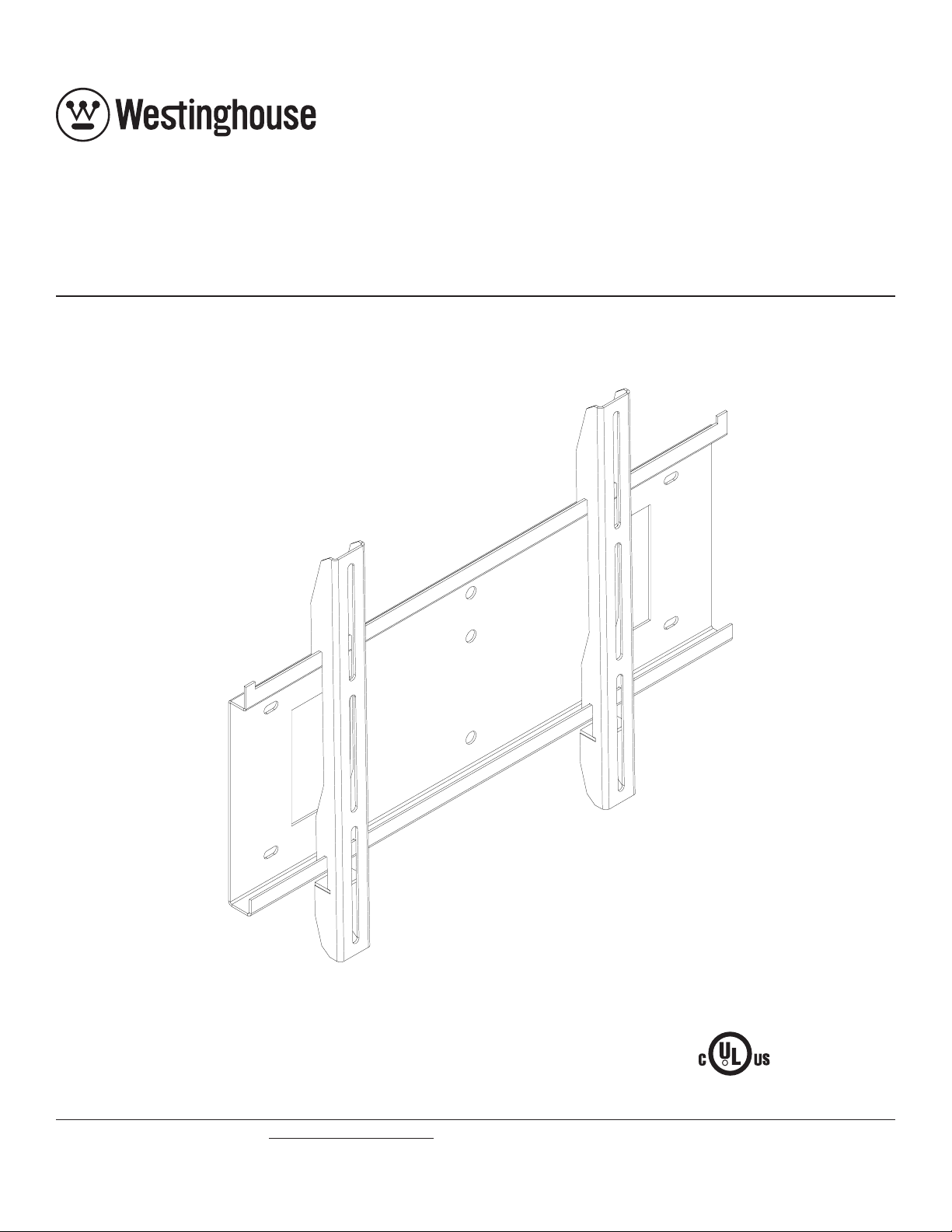
Universal Flat Wall Mount for 22" - 37" Screens
Model: MT80 THIN
Features:
• Universal design for 22" to 37" plasma and LCD screens
• Low-profile design keeps the screen close up against the wall
Visit the Westinghouse Web Site at www.westinghousedigital.com For customer service call 1-866-287-5555.
Max Load Capacity: 80 lb (36.3 kg)
R
ISSUED: 03-02-05 SHEET #: 201-9323-1
Page 2

Note: Read entire instruction sheet before you start installation and assembly.
WARNING
• Do not begin to install your Westinghouse product until you have read and understood the instructions and warnings
contained in this Installation Sheet. If you have any questions regarding any of the instructions or warnings, please
call Peerless customer service at 1-800-729-0307.
• Make sure that the wall will safely support the combined load of the equipment and all attached hardware and components.
• Never exceed the Maximum Load Capacity of 90 lb (40.8 kg).
• If mounting to wood wall studs, make sure that mounting screws are anchored into the center of the studs. Use of an
"edge to edge" stud finder is highly recommended.
• Always use an assistant or mechanical lifting equipment to safely lift and position equipment.
• Tighten screws firmly , but do not overtighten. Overtightening can damage the items, greatly reducing their holding
power.
Tools Needed for Assembly
• stud finder ("edge to edge" stud finder is recommended)
• phillips screwdriver
• drill with 1/4" and 5/32" drill bits
Table of Contents
Parts List..............................................................................................................................................................................3
Installation to Single Wood Stud Wall...................................................................................................................................4
Installation to Double Wood Stud Wall..................................................................................................................................5
Installation to Solid Concrete or Cinder Block .......................................................................................................................6
Installing Flat Panel Screen to Wall Plate.............................................................................................................................7
Adding Safety to Mount ........................................................................................................................................................7
For customer service call (800) 729-0307 or (708) 865-8870.
2 of 8
Visit the Westinghouse Web Site at www.westinghousedigital.com For customer service call 1-866-287-5555.
ISSUED: 03-02-05 SHEET #: 201-9323-1
Page 3
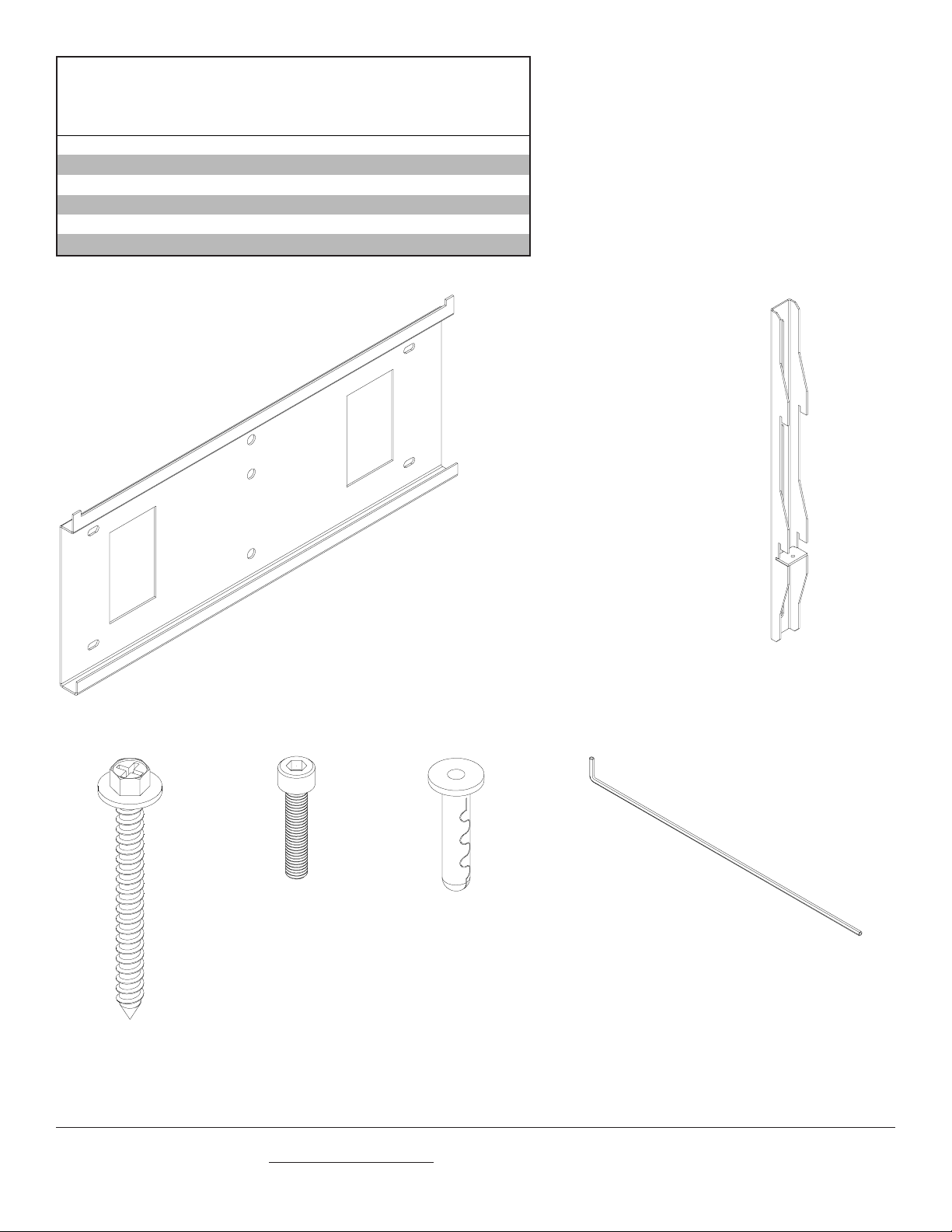
Before you begin, make sure all parts show n are included with your product.
Parts L ist
Description Qty Part #
wall plat e 1 200-4629
AA
adapter bracket 2 200-4628
BB
#14 x 2. 5" wood screw 4 5S1-015-C04
CC
M5 x . 8 x 25 mm s ocket head c ap screw 2 520-9567
DD
All i gat or® anchor 4 590-0097
EE
4 mm securit y allen wrench 1 560-1145
FF
MT80 T HIN
CC
AA
DD
BB
FF
EE
3 of 8
Visit the Westinghouse Web Site at www.westinghousedigital.com For customer service call 1-866-287-5555.
ISSUED: 03-02-05 SHEET #: 201-9323-1
Page 4
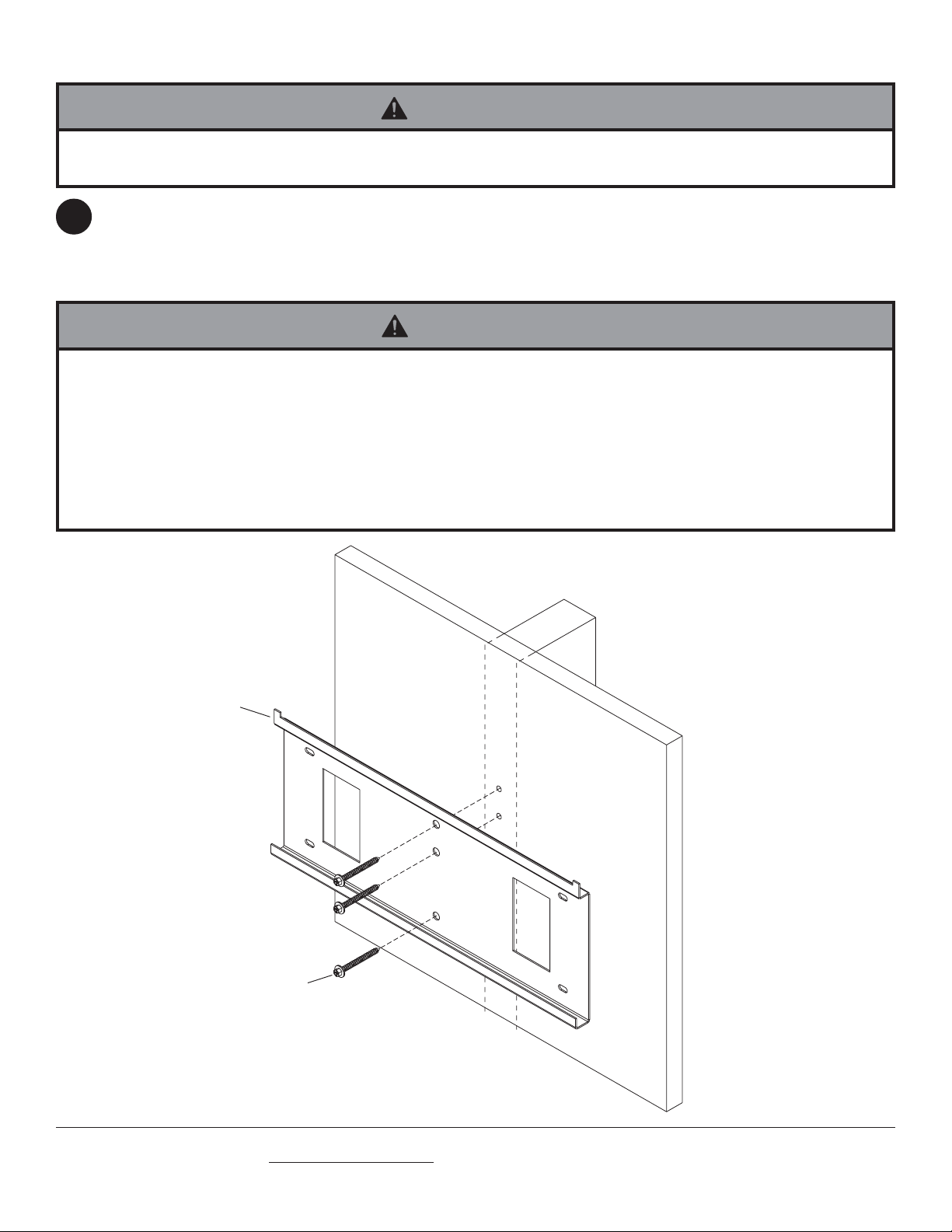
Installation to Single Wood Stud Wall
WARNING
• Installer must verify that the wall will safely support four times the combined weight of all attached equipment and
hardware.
Use stud finder to locate stud centers. Place wall plate (AA) on wall as template, level wall plate and mark center
1
of studs with pencil. Drill three 5/32" (4 mm) dia. holes 2-1/2" (65 mm) deep. Att ach wall plate (AA) using three #14
x 2.5" wood screws (CC).
Skip to step 2 on page 7.
WARNING
• Tighten wood screws so that wall plate is firmly attached, but do not overtighten. Overtightening can damage the
screws, greatly reducing their holding power.
• Never tighten in excess of 80 in. • lb (9 N.M.).
• Make sure that mounting screws are anchored into the center of the stud. The use of an "edge to edge" stud finder is
highly recommended.
• Hardware provided is for attachment of mount through standard thickness drywall or plaster into wood studs. Installers are responsible to provide hardware for other types of mounting situations.
AA
CC
4 of 8
Visit the Westinghouse Web Site at www.westinghousedigital.com For customer service call 1-866-287-5555.
ISSUED: 03-02-05 SHEET #: 201-9323-1
Page 5

Installation to Double Wood Stud Wall
WARNING
• Installer must verify that the wall will safely support four times the combined weight of all attached equipment and
hardware.
Use stud finder to locate stud centers. Place wall plate (AA) on wall as template, level wall plate and mark center
1
of studs with pencil. Drill four 5/32" (4 mm) dia. holes 2-1/2" (65 mm) deep. Att ach wall plate (AA) using four #14 x
2.5" wood screws (CC).
Skip to step 2 on page 7.
WARNING
• Tighten wood screws so that wall plate is firmly attached, but do not overtighten. Overtightening can damage the
screws, greatly reducing their holding power.
• Never tighten in excess of 80 in. • lb (9 N.M.).
• Make sure that mounting screws are anchored into the center of the stud. The use of an "edge to edge" stud finder is
highly recommended.
• Hardware provided is for attachment of mount through standard thickness drywall or plaster into wood studs. Installers are responsible to provide hardware for other types of mounting situations.
AA
CC
5 of 8
Visit the Westinghouse Web Site at www.westinghousedigital.com For customer service call 1-866-287-5555.
ISSUED: 03-02-05 SHEET #: 201-9323-1
Page 6

Installation to Solid Concrete or Cinder Block
WARNING
• When installing Westinghouse wall mounts on cinder block, verify that you have a minimum of 1-3/8" of actual concrete thickness in the hole to be used for the concrete anchors. Do not drill into mortar joints! Be sure to mount in a
solid part of the block, generally 1" minimum from the side of the block. Cinder block must meet ASTM C-90 specifications. It is suggested that a standard electric drill on slow setting is used to drill the hole instead of a hammer drill to
avoid breaking out the back of the hole when entering a void or cavity .
• Concrete must be 2000 psi density minimum. Lighter density concrete may not hold concrete anchor .
• Make sure that the wall will safely support four times the combined load of the equipment and all attached hardware
and components.
Use wall plate (AA), making sure that it is level, as
1
a template to mark holes. Drill four 1/4" (6 mm) dia.
holes to a minimum depth of 2-1/2" (64 mm). Insert
anchors (EE) in holes flush with wall as shown
(right). Place wall plate over anchors and secure
with #14 x 2.5" screws (CC). Tighten all fasteners.
WARNING
• Tighten screws so that wall plate is firmly attached,
but do not overtighten. Overtightening can damage
screws, greatly reducing their holding power.
• Never tighten in excess of 80 in. • lb (9 N.M.).
WARNING
• Always attach concrete expansion anchors directly to
load-bearing concrete.
• Never attach concrete expansion anchors to concrete covered with plaster, drywall, or other finishing
material. If mounting to concrete surfaces covered
with a finishing surface is unavoidable, the finishing
surface must be counterbored as shown below. If
plaster/drywall is thicker than 5/8", custom fasteners
must be supplied by installer .
1
Drill holes and insert anchors (EE).
2
AA
CC
Place plate (AA) over anchors (EE) and secure with
screws (CC).
3
Tighten all fasteners.
solid concrete
cinder block
AA
EE
concrete
surface
EE
EE
wall plate
CORRECT
concrete
plaster/
dry wall
INCORRECT
wall
plate
plaster/
CUT A WA Y VIEW
Visit the Westinghouse Web Site at www.westinghousedigital.com For customer service call 1-866-287-5555.
dry wall
concrete
6 of 8
CC
ISSUED: 03-02-05 SHEET #: 201-9323-1
Page 7

Note: Before starting this step refer to accompanying instruction sheet to install adapter bracket s to flat panel screen.
Installing Flat Panel Screen to Wall Plate
Insert two M5 x 25 mm socket head cap screws (DD) into mounting brackets (BB) and tighten a few turns to hold in
2
place as shown in detail 1. Hang screen by the mounting brackets (BB) on wall plate (AA) as shown below. Make
sure screen is safely hooked on mount before letting go. Screen can be adjusted horizontally if desired.
WARNING
• Always use an assistant or mechanical lifting equipment to safely lift and position the plasma television.
BB
BB
detail 1
Adding Safety to Mount
Secure mounting brackets to wall plate (AA) with socket head cap screws as shown below and in detail 1. Tighten
3
screws with 4 mm security allen wrench (FF).
AA
BB
DD
AA
DETAIL 1
7 of 8
Visit the Westinghouse Web Site at www.westinghousedigital.com For customer service call 1-866-287-5555.
ISSUED: 03-02-05 SHEET #: 201-9323-1
Page 8

Limited Five-Year Warranty
Westinghouse Digital Electronics warrants to original end-users of this Westinghouse television mounting product (the
“Product”) that the Product will be free from defects in material and workmanship, under normal use, for a period of five (5)
years from the date of purchase by the original end-user, subject to the following terms and conditions:
REP AIR OR REPLACEMENT – For a period of five (5) years from the original date of purchase, W estinghouse Digit al
Electronics will repair any defect in material or workmanship in the Product, or , at its option, replace a defective Product.
Replacement parts and products will be warranted for either the remainder of the original warranty period or ninety (90)
days from the date of delivery to the end-user, whichever occurs last.
OBT AINING WARRANTY SER VICE – To obtain warranty services, you must either personally deliver or ship the Product
to Westinghouse Digital Electronics, freight prepaid. Please call Westinghouse Digital Electronics at (866) 287-5555 to
obtain a Return Merchandise Authorization (“RMA”) and for other instructions regarding return and replacement or repair of
the Product. Westinghouse Digital Electronics will not accept Products delivered to it without an RMA.
EXCLUSIONS TO W ARRANTY – This warranty does not cover damage caused by (a) service or repairs by anyone other
than personnel authorized by Westinghouse Digital Electronics, (b) the failure to utilize proper packing when returning the
product, (c) improper installation or the failure to follow Product instructions or warnings, or (d) misuse or accident, in
transit or otherwise.
PROOF OR ORIGINAL PURCHASE – A sales receipt, invoice, or other proof of purchase specifying the original date of
purchase within the five (5) year warranty period must be presented to obtain warranty service. This warranty extends to
the original purchaser and is not transferable.
EITHER REP AIR OR REPLACEMENT IS YOUR EXCLUSIVE REMEDY UNDER THIS WARRANTY. EXCEPT TO THE
EXTENT PROHIBITED BY LAW, WESTINGHOUSE DIGITAL SHALL NOT BE LIABLE FOR ANY INCIDENTAL OR
CONSEQUENTIAL DAMAGES CLAIMED T O ARISE FROM BREACH OF ANY EXPRESS OR IMPLIED W ARRANTY ON
THIS PRODUCT . ANY IMPLIED WARRANTY OF MERCHANT ABILITY OR FITNESS FOR A P ARTICULAR PURPOSE
ON THIS PRODUCT IS LIMITED IN DURA TION AND SCOPE TO THE TERMS OF THIS WARRANTY.
Some States do not allow the exclusion or limit ation of incidental or consequential damages, or allow limitations on how
long an implied warranty lasts, so the above limitation may not apply to you. This warranty gives specific legal rights, and
you may also have other rights which vary from S tate to S tate.
Westinghouse Digital Electronics, LLC
16257 East Gale A ve.
City of Industry , California 91745
T el: (626) 333-9677.
8 of 8
Visit the Westinghouse Web Site at www.westinghousedigital.com For customer service call 1-866-287-5555.
and Westinghouse are trademarks of Westinghouse Electric Corporation and are used under license.
ISSUED: 03-02-05 SHEET #: 201-9323-1
Page 9

Installing Adapter Brackets to
the Flat Panel Screen
Begin with product installation and assembly manual before reading this instruction manual.
Par t s Li st
De scription Qty. Par t #
A M4 x .7 x 12 mm phi l l ips screw 6 504-9013
C M4 x .7 x 25 mm phi l l ips screw 6 504-1015
E M 5 x 40 mm pan head phillips scew 4 520-1199
F M6 x 25 mm pan head phi l l ips screw 4 520-1208
G M6 x 1 x 20 mm pan head phi llips screw 4 520-9402
H M5 x .8 x 12 mm pan head phillps sc rew 4 520-1027
I M6 x 1 x 12 m m pan head philli ps screw 6 520-1128
K M5 x 25 mm pan head phi l l ips screw 6 520-9543
O multi-washer 6 580-1036
S .25" ID x .5" OD x .625" H nylon s pacer 4 590-1106
V .251" ID x .5" OD x 1.25" H al um inum spacer 4 580-1067
Model: MT80 THIN
E G
OI
FA C H
S VK
BB
Note: This part is listed on the
product installation and assembly manual.
1 of 4
Visit the Westinghouse Web Site at www.westinghousedigital.com For customer service call 1-866-287-5555.
ISSUED: 01-18-05 SHEET #: 201-9325-1
Page 10

To assemble the adapter brackets to your screen, begin with the table on pages 2 and 3. Find the configuration
(
)
A
A
A
A
A
A
A
A
A
A
A
A
A
A
V
A
A
A
A
A
y
A
A
A
A
that corresponds to your screen. Refer to the configuration table on page 3 to install the adapter brackets.
Notes: The Universal Flat Wall Mount
is a universal mount which accommodates a wide variety of screens. If your particular
screen is not listed on pages 2 and 3 or unsure which configuration matches your screen, please contact customer service
to ensure product compatibility .
Screen
Size
Akai 22" LC2260 K
BenQ 30"
CTX 23" H2300 K
Dell 23" W2300 K
Dell 26"
Dell 30"
Gateway 23" GTW-L23M102 K
Gateway 26"
Gateway 30"
Hewlett Packard 23" f2304 K
IBM 22.2" T221 K
Image Systems 24" FP2400MAX K
JVC 23" LT23X475 K
JVC 26"
JVC 32"
LG 22" 285LT, 295LM K
LG 23"
LG 27"
LG 30"
LG 30"
LG 30"
LG 32"
Maxx Products 30"
Luce 22" LCTV2201A / GB K
MAXENT 27"
MAXENT 30"
Mitsubishi 22" LT-2220, LT-2240 K
Mitsubishi 30"
Mitsubishi 30"
NEC-Mitsubishi 30"
Net T
Ovideon 27"
Ovideon 30"
Panasonic 22" TC-22LH1 K
Panasonic 26"
Panasonic 32"
Panasonic 32"
Philips 23" 23FW995/997, 23PF9945 K
Philips 23" 23PF8946, 23PF8946A K
Philips 23" 23PF9966 K
Philips 26"
Philips 30"
PixelPro 27"
PixelPro 30"
Planar 22" XP22WSA-01 K
Planar 23.1" WS231 K
Samsung 22" LTM225W, LTN226W K
Samsung 24"
Samsung 26"
Sceptre 23" Naga X23S K
Sceptre 30" X30SV- Naga III
Sharp 26"
Sharp 30"
Sharp 32"
Sharp 37" LC-37HV4U, LC-M3700, LC-37HV6U, LC-37G4U, LC-37GD4U, LC-37GD6U
Sony 23" LMD-230WS K
Sony 23"
Sony 23"
Sony 26"
Sony 30"
30"
DV3080
DV3070
W2600
W3000
GTW-L26M103
GTW-L30M103
LT26WX84, LT26X575 F
LT32WX84, LT32X575 F
RU-23LZ21, RU-23LZ50C, L2320A, L2323T K
RU-27LZ50C
L3000A F
L3020T, RU-30LZ50C
DU-30LZ30
RU-32LZ50C
MAXX 3000 I
MX-27X1
MX-30X1
LT-3020, LT-3040, LT-3050
MLM300
LCD3000
LCTV-30W
LC2700w
LC3000W
TC-26LX20 C
TC-32LX20 C
TC32LH1 C
26PF9966
30PF9975, 30FW9955, 30FW9975, 30FW995, 30FW997 F
PX-27XP10
PX-30XP10
ncmaster 204T, 240T, 243T K
S
LT-P266W
LC-26GA4U, LC-26GD4U, LC-26GD6U
LC-30HV2U, LC-30HV4U, LC-30HV6U
LC-32G4U, LC-32GD4U, LC-32GD6U L
KLV-23HR2, SDM-232W/B K
KLV-23M1 K
KLV-26HG2
KLV-30XBR900, KLV-30XBR950, LDM3000 F
LCD Screens
Config.Manufacturer Manufacturer Model
I
A
L
Continued on the following page...
2 of 4
Visit the Westinghouse Web Site at www.westinghousedigital.com For customer service call 1-866-287-5555.
ISSUED: 01-18-05 SHEET #: 201-9325-1
Page 11

Screen
A
A
A
T
T
A
T
A
A
A
A
A
A
A
A
A
A
A
Sony 32"
Sony 32"
Studio Experience 30"
Syntax 27"
Syntax 30"
Tatung 23" V23CLT
Tatung 27"
Tatung 30"
Toshiba 26"
Toshiba 26"
Toshiba 32"
ToteVision 22"
ViewSonic 22.2" VP2290b K
ViewSonic 23" VP230mb K
Viewsonic 27"
Viewsonic 30"
Viewsonic 30"
Westinghouse 27"
Westinghouse 27"
Westinghouse 30"
Westinghouse 30"
Westinghouse 32"
Westinghouse 37"
Westinghouse 37"
Zenith 23" L23W36 K
Zenith 27"
Eiki 32" PLD-32U G
Hitachi 32" 32HDT20, 32HDT50, 32HDT55, 32HDT60 B
Hitachi 37” CMP307SX, CMP307U, CMP307XU B
Maxx Products 32" MAXX 3200 I
Monovision 32" PD3231 I
Philips 32" 32FD9954, 32FW997 F
Philips 37" 37FD9944, 37FD9954/17, 37PF9965 F
Sanyo 32" PDP-32H1A G
Sony 32" KZ-32TS1U, KZ-32TS1, KE-32TS2 H
Studio Experience 32" SEPD3200, SEPD3231 I
Size
KDL-32XBR950 G
KLV-32M1
SELCD300 I
LT27HV
LT30HV
V27CMT
V30CMT
26HL83
26HL84
32HL84
LCD-2200VT, LCD-2216TD K
N2700w I
N3000w C
N3020w C
LTV-27w2
W32701
LTV-30w2 C
W33000, W33001
LTV-32w1
LTV-37w2 HD
LVM-37w1
L27W46
Plasma Screens
Config.Manufacturer Manufacturer Model
K
Using your screen's configuration letter from the
1
previous table, find the configuration that
corresponds to your screen. Refer to the table
below to find which fasteners to use when installing
the adapter brackets and use the corresponding
hole in the multi-washer (O) that matches your
screw size as shown in figure 1.
TOP HOLE FOR M5 SCREWS
MIDDLE HOLE FOR M4 SCREWS
BOTTOM HOLE FOR M6 SCREWS
TOP
O
Config. Screws Spacer
A Ano
B Ino
C CS
fig. 1
BOTTOM
F Hno
G KS
H EV
I FS
*K Ano
**L Ino
**Note: If screws (A) do not engage with four complete
turns, then use screws (C) with spacer (S).
**Note: If screws (I) do not engage with the threads
inside the mounting hole then use screws (G).
If screws (G) are not long enough then use
screws (F).
3 of 4
Visit the Westinghouse Web Site at www.westinghousedigital.com For customer service call 1-866-287-5555.
ISSUED: 01-18-05 SHEET #: 201-9325-1
Page 12

Installing Adapter Brackets
T o prevent scratching the screen, set a cloth on a flat, level surface that will support the weight of the screen. Place
2
screen face side down. If screen has knobs on the back, remove them to allow the adapter brackets to be attached.
Place adapter brackets (BB) on back of screen, align to holes, and center on back of screen as shown in figure 2.1.
Refer to step 1 to determine the proper fasteners to use. Attach the adapter brackets to the back of the screen using
the appropriate combination of screws, multi-washers (O), and spacers as shown in figure 2.2. Verify that all holes are
properly aligned, and then tighten screws using a phillips screwdriver .
WARNING
X
• Tighten screws so adapter brackets are firmly
attached. Do not tighten with excessive force.
Overtightening can cause stress damage to
screws, greatly reducing their holding power and
possibly causing screw heads to become
detached. Tighten to 40 in. • lb (4.5 N.M.)
maximum torque.
Notes:
• The number of fasteners used will vary ,
depending upon the type of screen.
• Spacers may not be used, depending upon
the type of screen.
BB
fig 2.1
BB
CENTER BRACKETS VERTICALLY
ON BACK OF SCREEN
BB
X
Note: "X" dimensions should be equal.
SCREWS
O
BB
SPACERS
fig 2.2
4 of 4
Visit the Westinghouse Web Site at www.westinghousedigital.com For customer service call 1-866-287-5555.
and Westinghouse are trademarks of Westinghouse Electric Corporation and are used under license.
ISSUED: 01-18-05 SHEET #: 201-9325-1
 Loading...