

Page 1
Web Interface and
Command Line
Reference Guide
6622-3201
MR-250, DR-250
MR-200
3G Router
ADSL Router
GPRS Router
www.westermo.com
Page 2

www.westermo.com
Web Interface and Command Line Reference Guide
Legal information
The contents of this document are provided “as is”. Except as required by applicable law, no warranties of any kind, either express or implied, including, but not limited to, the implied warranties of
merchantability and fitness for a particular purpose, are made in relation to the accuracy and reliability or contents of this document. Westermo reserves the right to revise this document or withdraw it at any time without prior notice.
Under no circumstances shall Westermo be responsible for any loss of data or income or any special, incidental, and consequential or indirect damages howsoever caused.
More information about Westermo can be found at the following Internet address:
www.westermo.com
2
6622-3201
Page 3

Web Interface and Command Line Reference Guide
Typographical Conventions 1.
Throughout this manual certain typographical conventions are used as follows:
Text Type Meaning
Text like this
Note:
Text like this
Text like this
Text like this
Configure > Save
is standard text.
indicates points that are of particular importance.
indicates commands entered by the user at the command line.
indicates responses from the unit to commands you enter at the command line.
refers to the unit’s web-based menu system.
www.westermo.com
6622-3201
3
Page 4

www.westermo.com
Web Interface and Command Line Reference Guide
Table of Contents
1. ........................................... Typographical Conventions ................................................... 3
2............................................ Using the Web Interface ....................................................... 12
2.1 .............................................. Access Via a LAN Port ............................................................................. 12
2.2 .............................................. Access Via a Serial Port ............................................................................ 12
2.2.1 ................................... Installing the Driver File ........................................................................... 13
2.2.2 ................................... Creating A New Dial-Up Network Connection ................................ 17
2.2.3 ................................... Configuring the New DUN Connection ..............................................20
2.2.4 ................................... Initiating a DUN Connection .................................................................. 22
3............................................ Using the command line interface ...................................... 24
3.1 .............................................. The “AT” Command Interface ............................................................... 24
3.1.1 ................................... Command Prefix ........................................................................................ 24
3.1.2 ................................... The Escape Sequence ................................................................................25
3.1.3 ...................................Result Codes ............................................................................................... 25
3.1.4 ................................... “S” Registers ............................................................................................... 25
3.2 .............................................. Westermo Application Commands ....................................................... 26
3.2.1 ................................... The Reboot Command ............................................................................26
3.2.2 ...................................The Active Port ..........................................................................................27
3.3 .............................................. Establishing a Remote Connection ........................................................ 27
4............................................ Configuring your unit ............................................................ 28
4.1 .............................................. Logging In ..................................................................................................... 28
4.2 .............................................. Configuring and Testing W-WAN Models ............................................ 30
4.2.1 ................................... Signal Strength Indicators .........................................................................30
4.3 .............................................. The Configuration Pages .......................................................................... 31
4.4 .............................................. Configure > ADAPT > ADAPT n ...........................................................32
4.5 .............................................. Configure > Analyser ................................................................................ 35
4.6 .............................................. Configure > ASY Ports > ASY Port n ...................................................42
4.7 .............................................. Configure > TRANSIP ASY Ports ...........................................................45
4.8 .............................................. Configure > Backup IP Addresses ..........................................................47
4.9 .............................................. Configure > Basic .......................................................................................48
4.10 ............................................ Configure > BGP ........................................................................................ 49
4.11 ............................................ Configure > Certificates > Certificate request .................................. 59
4.12 ............................................ Configure > Certificates > SCEP ........................................................... 61
4.13 ............................................ Configure > Certificates > Utilities ....................................................... 63
4.14 ............................................ Configure > Calling Numbers ................................................................. 65
4.15 ............................................ Configure > Command Filters ................................................................ 66
4.16 ............................................ Configure > Command Mappings .......................................................... 67
4.17 ............................................ Configure > DHCP Servers > Ethernet Port n .................................68
4.18 ............................................ Configure > DHCP Options > DHCP option n ................................ 71
4.19 ............................................ Configure > DHCP Server > MAC –>IP Addresses .........................72
4.20 ............................................ Configure > DNS Server selection > DNS server selection n ...... 73
4.21 ............................................ Configure > DNS Server Update .......................................................... 75
4.22 ............................................ Configure > DSL > ADSL ........................................................................ 78
4.23 ............................................ Configure > DSL > ATM PVCs > PVC n ............................................. 80
4.24 ............................................ Configure > Dynamic DNS ..................................................................... 82
4.25 ............................................ Configure > Ethernet > ETH n .............................................................. 84
4.26 ............................................ Configure > Ethernet > ETH n > QOS ............................................... 93
............................................Configure > Ethernet > ETH n > VRRP Probing ............................... 95
4.27
4.28 ............................................ Configure > Ethernet > MAC Filters .................................................... 97
4
6622-3201
Page 5

Web Interface and Command Line Reference Guide
4.29 ............................................ Configure > Ethernet > VLANs .............................................................. 98
4.30 ............................................ Configure > Event Handler ...................................................................100
4.31 ............................................ Configure > Event Logcodes ................................................................. 105
4.31.1 ................................. Configuring Events ...................................................................................105
4.31.2 ................................. Configuring Reasons ................................................................................ 107
4.32 ............................................ Configure > Firewall ................................................................................109
4.33 ............................................ Configure > Firewall Options ...............................................................111
4.34 ............................................ Configure > FTP Client ..........................................................................113
4.35 ............................................ Configure > FTP Relay Agents > RELAY n ........................................ 114
4.36 ............................................ Configure > General ............................................................................... 117
4.37 ............................................ Configure > IP Routes > RIP > RIP update options .......................125
4.38 ............................................ Configure > IP Routes > RIP > RIP access list .................................126
4.39 ............................................ Configure > IP Routes > Route n ........................................................127
4.40 ............................................ Configure > IP Routes > RIP > Authentication keys > Key n .......131
4.41 ............................................ Configure > IP Routes > Default Route n .........................................133
4.42 ............................................ Configure > IPSec ....................................................................................133
4.43 ............................................ Configure > IPSec > DPD .....................................................................134
4.44 ............................................ Configure > IPSec > IKE > MODECFG > Static NAT Mappings .136
4.45 ............................................ Configure > IPSec > IKE > IKE n .........................................................138
4.46 ............................................ Configure > IPSec > IKE > Responder ...............................................141
4.47 ............................................ Configure > IPSec > IKEv2 > IKEv2 n ................................................146
4.48 ............................................ Configure > IPSec > IKEv2 > Responder ..........................................148
4.49 ............................................ Configure > IPSec > IPSec Egroups > Egroup n ...............................150
4.50 ............................................ Configure > IPSec > IPSec Eroutes > Eroute n ................................155
4.50.1 ................................. Setting up Eroutes for Multiple Users ................................................163
4.51 ............................................ Configure > IPSec > Default Eroute ...................................................164
4.52 ............................................ Configure > ISDN LAPB > LAPB n .....................................................165
4.53 ............................................ Configure > ISDN LAPD > LAPD n ...................................................168
4.54 ............................................ Configure > L2TP > L2TP n .................................................................171
4.55 ............................................ Configure > OSPF ....................................................................................174
4.56 ............................................ Configure > PPP .......................................................................................177
4.57 ............................................ Configure > PPP > MLPPP .....................................................................178
4.58 ............................................ Configure > PPP > External Modems > External Modem n .........181
4.59 ............................................ Configure > PPP > Sub-Configs > Sub-Config n ..............................183
4.60 ............................................ Configure > PPP > PPP n > Standard .................................................184
4.61 ............................................ Configure > PPP > PPP n > Advanced ................................................192
4.62 ............................................ Configure > PPP > PPP n > PPP/IP Over X25 .................................200
4.63 ............................................ Configure > PPP > PPP n > QOS ........................................................202
4.64 ............................................ Configure > PPTP ....................................................................................204
4.65 ............................................ Configure > Protocol Bindings ............................................................. 206
4.65.1 ................................. Binding TANS to ADAPT ........................................................................206
4.66 ............................................ Configure > Protocol Switch ................................................................ 207
4.67 ............................................ Configure > Protocol Switch > CUD Mappings ..............................215
4.68 ............................................ Configure > Protocol Switch > NUA Mappings ...............................216
4.69 ............................................ Configure > PSTN Modem ....................................................................217
4.70 ............................................ Configure > Quality of Service ............................................................218
4.70.1 ................................. Introduction ...............................................................................................218
4.70.2 ................................. Basic Operation ........................................................................................218
4.71 ............................................ Configure > Quality of Service > DSCP Mappings ..........................220
4.72 ............................................ Configure > Quality of Service > Q Profiles > Q Profile n ..........221
4.73 ............................................ Configure > RADIUS client ...................................................................223
4.74 ............................................ Configure > SMS Edit ..............................................................................226
4.75 ............................................ Configure > SMTP ...................................................................................227
4.76 ............................................ Configure > SNAIP > SNAIP n ............................................................229
www.westermo.com
6622-3201
5
Page 6

www.westermo.com
4.77 ............................................ Configure >SNMP .................................................................................... 235
4.78 ............................................ Configure >SNMP Filters .......................................................................237
4.79 ............................................ Configure >SNMP > Trap Servers > Trap Server n .........................238
4.80 ............................................ Configure >SNMP > Users > User n .................................................240
4.81 ............................................ Configure > STP .......................................................................................242
4.82 ............................................ Configure > NTP .....................................................................................244
4.83 ............................................ Configure > SNTP ...................................................................................246
4.84 ............................................ Configure > SSH server .........................................................................248
4.84.1 ................................. Complete SSH Configuration ...............................................................251
4.84.2 ................................. SSH Authentication with a public/private keypair. ............................252
4.85 ............................................ Configure > SSL clients > SSL Client n ..............................................253
4.86 ............................................ Configure > SSL server ..........................................................................254
4.87 ............................................ Configure > Static Multicast Routes ...................................................255
4.88 ............................................ Configure > Static NAT Mappings .......................................................256
4.89 ............................................ Configure > SYNC Ports > SYNC n ..................................................258
4.90 ............................................ Configure > Syslog Clients > Syslog n ................................................ 259
4.91 ............................................ Configure > System Messages ..............................................................261
4.92 ............................................ Configure > TACACS+ ...........................................................................262
4.93 ............................................ Configure > TANS > TANS n ................................................................264
4.94 ............................................ Configure > Time .....................................................................................267
4.95 ............................................ Configure > Time Bands > Time Band n ............................................268
4.96 ............................................ Configure > TPAD > TPAD Statistics ..................................................270
4.97 ............................................ Configure > TPAD > TPAD n ...............................................................271
4.98 ............................................ Configure > Tunnel (GRE) .....................................................................280
4.99 ............................................ Configure > UDP Echo Client/Server > UDP Echo n ....................283
4.100 ......................................... Configure > Users > User n .................................................................285
4.101 ......................................... Configure > VXN client ..........................................................................288
4.102 ......................................... Configure > W-WAN ..............................................................................291
4.102.1 ............................... Additional Configuration for wireless .................................................296
4.103 ......................................... Configure > W-WAN module > Cell Monitor .................................297
4.104 ......................................... Configure > X25 > NUI Mappings ...................................................... 299
4.105 ......................................... Configure > X25 ......................................................................................300
4.106 ......................................... Configure > X25 > Macros ...................................................................302
4.107 ......................................... Configure > X25 > IP–>X25 Calls ......................................................303
4.108 ......................................... Configure > X25 > NUA/NUI–>Interface ........................................306
4.109 ......................................... Configure > X25 > PADs > PAD n .....................................................308
4.110 ......................................... Configure > X25 > PADs > PAD n > Parameters ..........................313
4.110.1 ............................... PAD Recall Character .............................................................................313
4.110.2 ............................... Echo .............................................................................................................313
4.110.3 ............................... Data Forwarding Characters .................................................................313
4.110.4 ............................... Idle Timer Delay .......................................................................................314
4.110.5 ............................... Ancillary Device Control .......................................................................314
4.110.6 ............................... Suppression of PAD Service Signals ....................................................314
4.110.7 ............................... Action on Break (from DTE) ................................................................314
4.110.8 ............................... Discard Output ........................................................................................315
4.110.9 ............................... Padding after CR ......................................................................................315
4.110.10 ............................. Line Folding ...............................................................................................315
4.110.11 ............................. Port Speed .................................................................................................315
4.110.12 ............................. Flow Control of PAD (by DTE) ........................................................... 315
4.110.13 ............................. LF Insertion (after CR) ........................................................................... 316
4.110.14 ............................. LF Padding ..................................................................................................316
4.110.15 ............................. Editing .........................................................................................................316
4.110.16 ............................. Character Delete Character .................................................................316
4.110.17 ............................. Line Delete Character ............................................................................316
Web Interface and Command Line Reference Guide
6
6622-3201
Page 7

Web Interface and Command Line Reference Guide
4.110.18 ............................. Line Redisplay Character .......................................................................316
4.110.19 ............................. Editing PAD Service Signals ...................................................................317
4.110.20 ............................. Echo Mask ..................................................................................................317
4.110.21 ............................. Parity Treatment .......................................................................................317
4.110.22 ............................. Page Wait ...................................................................................................318
4.111 ......................................... Configure > X25 > PVCs > PVC n .....................................................319
4.112 ......................................... Saving Configuration Settings. ............................................................... 321
4.112.1 ............................... Config Files ................................................................................................321
4.112.2 ............................... SREGS.DAT ................................................................................................321
4.112.3 ............................... PWDS.DA0 ................................................................................................321
4.112.4 ............................... Factory Reset ............................................................................................322
4.112.5 ............................... Universal config.da0 using tags .............................................................322
5............................................ Statistics Pages .................................................................... 324
5.1 .............................................. Statistics > ATM PVCs > PVC n ...........................................................325
5.2 .............................................. Statistics > ADAPT > ADAPT n ...........................................................325
5.3 .............................................. Statistics > ADSL ......................................................................................326
5.4 .............................................. Statistics > ASY Ports ............................................................................. 326
5.5 .............................................. Statistics > DNS Update ........................................................................327
5.6 .............................................. Statistics > Ethernet > ETH n ..............................................................328
5.7 .............................................. Statistics > Ethernet > ETH n > QOS ...............................................329
5.8 .............................................. Statistics > Firewall ..................................................................................330
5.9 .............................................. Statistics > W-WAN Port ......................................................................330
5.10 ............................................ Statistics > IP .............................................................................................331
5.11 ............................................ Statistics > PPP > PPP n .........................................................................332
5.11.1 ................................. PPP n Stats .................................................................................................332
5.11.2 ................................. Transaction Stats ...................................................................................... 333
5.12 ............................................ Statistics > PPP > PPP n > QOS ..........................................................333
5.13 ............................................ Statistics > SYNC Channels ..................................................................334
5.13.1 ................................. ISDN D Channel ......................................................................................334
5.13.2 ................................. ISDN B1 Channel .....................................................................................335
5.13.3 ................................. ISDN B2 Channel .....................................................................................335
5.13.4 ................................. Physical Port 0 ..........................................................................................336
5.14 ............................................ Statistics > TPAD > TPAD n ..................................................................336
5.14.1 ................................. TPAD Stats ................................................................................................336
5.14.2 ................................. Layer 3 X25 Stats .....................................................................................338
5.14.3 ................................. Layer 2 LAPB Stats ..................................................................................338
5.14.4 ................................. Layer 1 B1 Sync Stats ..............................................................................339
5.14.5 ................................. Layer 2 LAPD Stats .................................................................................340
5.14.6 ................................. D Channel Stats .......................................................................................340
5.14.7 ................................. Layer 1 D Sync Stats ............................................................................... 341
5.15 ............................................ Statistics > X25 PADs > PAD n ..........................................................342
5.15.1 ................................. Layer 3 X25 Stats .....................................................................................342
5.15.2 ................................. Layer 2 LAPD Stats .................................................................................342
5.15.3 ................................. D Channel Stats .......................................................................................343
5.15.4 ................................. Layer 1 D Sync Stats ............................................................................... 343
www.westermo.com
6............................................ Status Pages ........................................................................ 344
6.1 .............................................. Status > Analyser Trace ...........................................................................344
6.2 .............................................. Status > PCAP traces .............................................................................344
6.3 .............................................. Status > DHCP Server ...........................................................................345
6.4 .............................................. Status > Ethernet > ETH n ...................................................................346
6.5 .............................................. Status > Ethernet > ETH n > QOS ....................................................347
6.6 .............................................. Status > Event log ....................................................................................347
6622-3201
7
Page 8

www.westermo.com
Web Interface and Command Line Reference Guide
6.7 .............................................. Status > File Directory ...........................................................................347
6.8 .............................................. Status > Firmware Versions ...................................................................348
6.9 .............................................. Status > W-WAN Module ......................................................................348
6.10 ............................................ Status > W-WAN Module > Neighbour Cells ..................................352
6.11 ............................................ Status > W-WAN Module > Serving Cell ..........................................353
6.12 ............................................ Status > W-WAN Module > W-WAN Cell Information ................355
6.13 ............................................ Status > IGMP Groups ...........................................................................357
6.14 ............................................ Status > IPSec > IPSec Peers .................................................................357
6.15 ............................................ Status > IPSec > IKE SAs .......................................................................358
6.16 ............................................ Status > IPSec > IPSec SAs > Dynamic tunnels ...............................358
6.17 ............................................ Status > IPSec > IPSec SAs > Eroute n ..............................................359
6.18 ............................................ Status > ISDN BRI ................................................................................... 360
6.19 ............................................ Status > Web Directory .........................................................................360
6.20 ............................................ Status > Web Server ...............................................................................360
6.21 ............................................ Status > X.25 Sessions ...........................................................................361
7............................................ The Filing System ............................................................... 362
7.1 .............................................. System Files ...............................................................................................362
7.2 .............................................. Filing System Commands .......................................................................362
7.2.1 ................................... COPY Copy File .......................................................................................362
7.2.2 ................................... DEL Delete File ........................................................................................362
7.2.3 ................................... DIR List File Directory ............................................................................363
7.2.4 ................................... FLOCK Lock Files ...................................................................................363
7.2.5 ................................... FUNLOCK Unlock Files ........................................................................ 363
7.2.6 ................................... MOVE Move File ......................................................................................363
7.2.7 ................................... REN Rename File ..................................................................................... 363
7.2.8 ................................... SCAN/SCANR Scan File System ..........................................................364
7.2.9 ................................... TYPE Display Text File ...........................................................................364
7.2.10 ................................. XMODEM File Transfer ..........................................................................364
7.3 .............................................. USB Support .............................................................................................365
7.3.1 ................................... SD Memory Card Support .................................................................... 365
7.3.2 ................................... Batch Control Commands .....................................................................365
7.3.3 ................................... USB Filing System Commands ..............................................................365
7.3.4 ................................... Using USB devices to upgrade firmware ............................................366
7.3.5 ................................... Using USB devices with .all files ...........................................................366
7.3.6 ...................................USB Security .............................................................................................366
7.3.7 ................................... Disable/Enable the USB ports ...............................................................367
8............................................ SQL Commands .................................................................. 369
9............................................ Using V.120 ........................................................................... 372
9.1 .............................................. Initial Set Up ..............................................................................................372
9.2 .............................................. Initiating a V.120 Call ...............................................................................372
9.3 .............................................. Answering V.120 Calls .............................................................................373
10 .........................................Answering ISDN Calls ......................................................... 374
10.1 ............................................ Protocol Entities .......................................................................................374
10.2 ............................................ Multiple Subscriber Numbers ...............................................................375
10.3 ............................................ Multiple PPP Instances ............................................................................375
11 .........................................X.25 Packet Switching ........................................................ 376
11.1 ............................................ Introduction ...............................................................................................376
11.2 ............................................ B-channel X.25 .........................................................................................376
8
6622-3201
Page 9

Web Interface and Command Line Reference Guide
11.3 ............................................ D-channel X.25 .........................................................................................376
11.4 ............................................ X.28 Commands ...................................................................................... 377
11.4.1 ................................. CALL Make an X.25 Call .......................................................................377
11.4.2 ................................. Aborting a CALL ......................................................................................379
11.4.3 ................................. CLR Clear an X.25 Call .........................................................................381
11.4.4 ................................. ICLR Invitation To CLR ...........................................................................381
11.4.5 ................................. INT Send Interrupt Packet ....................................................................381
11.4.6 ................................. LOG Logoff and Disconnect .................................................................381
11.4.7 ................................. PAR? List Local X.3 Parameters ...........................................................381
11.4.8 ................................. PROF Load/Save PAD Profile ................................................................382
11.4.9 ................................. RESET Send Reset Packet ......................................................................383
11.4.10 ............................... RPAR? Read Remote X.3 Parameters .................................................383
11.4.11 ............................... RSET Set Remote X.3 Parameters ......................................................383
11.4.12 ............................... SET Set Local X.3 Parameters ..............................................................383
12 .........................................PPP Over Ethernet ............................................................. 384
13 ......................................... IPSEC and VPNs .................................................................. 385
13.1 ............................................ What is IPSec? ..........................................................................................385
13.2 ............................................ Data Encryption Methods ......................................................................385
13.2.1 ................................. DES (64-bit key) .......................................................................................385
13.2.2 ................................. DES (192-bit key) .....................................................................................386
13.2.3 ................................. AES (128-bit key) .....................................................................................386
13.3 ............................................ What is a VPN? .........................................................................................386
13.4 ............................................ The Benefits of IPSec ..............................................................................386
13.5 ............................................ X.509 Certificates ....................................................................................387
www.westermo.com
14 .........................................The Event Log ...................................................................... 389
14.1 ............................................ What is the Event Log? ..........................................................................389
14.2 ............................................ The LOGCODES.TXT File ...................................................................390
14.2.1 ................................. Event Blocks .............................................................................................391
14.2.2 ................................. Reason Blocks ...........................................................................................391
14.2.3 ................................. Editing the File ..........................................................................................391
15 ......................................... Firewall Scripts .................................................................... 392
15.1 ............................................ Introduction ...............................................................................................392
15.2 ............................................ Firewall Script Syntax ..............................................................................392
15.2.1 ................................. Labels ..........................................................................................................392
15.2.2 ................................. Comments .................................................................................................392
15.2.3 ................................. Filter Rules .................................................................................................393
15.3 ............................................ Specifying IP Addresses and Ranges .....................................................397
15.4 ............................................ Address/Port Translation ........................................................................398
15.5 ............................................ Filtering on Port Numbers ....................................................................398
15.6 ............................................ Filtering on TCP Flags .............................................................................400
15.7 ............................................ Filtering on ICMP Codes .......................................................................401
15.8 ............................................ Stateful Inspection ....................................................................................402
15.8.1 ................................. Using [inspect-state] with Flags ............................................................403
15.8.2 ................................. Using [inspect-state] with ICMP ..........................................................403
15.8.3 ................................. Using [inspect-state] with the Out Of Service Option ..................404
15.8.4 ................................. Using [inspect-state] with the Stat Option .......................................405
15.8.5 ................................. Assigning DSCP Values ............................................................................405
15.9 ............................................ The FWLOG.TXT File ...........................................................................406
15.9.1 ................................. Log File Examples .....................................................................................407
6622-3201
9
Page 10

www.westermo.com
Web Interface and Command Line Reference Guide
15.10 ......................................... Further [inspect-state] Examples .........................................................408
15.11 ......................................... Debugging a Firewall ...............................................................................410
16 ......................................... Remote Management .......................................................... 411
16.1 ............................................ Using V.120 .................................................................................................411
16.2 ............................................ Using Telnet ...............................................................................................411
16.3 ............................................ Using FTP ...................................................................................................411
16.3.1 ................................. FTP under Windows ...............................................................................412
16.3.2 ................................. FTP under DOS .......................................................................................412
16.4 ............................................ Using X.25 .................................................................................................412
17 ......................................... AT Commands ..................................................................... 413
17.1 ............................................ D Dial .........................................................................................................413
17.1.1 ................................. Dialling with a Specified Sub-Address .................................................413
17.1.2 ................................. Dialling Stored Numbers .......................................................................413
17.1.3 ................................. Combining ISDN and X.25 Calls .........................................................413
17.2 ............................................ H Hang-up ................................................................................................ 413
17.3 ............................................ Z Reset .....................................................................................................413
17.4 ............................................ &C DCD Control ....................................................................................414
17.5 ............................................ &F Load Factory Settings ....................................................................... 414
17.6 ............................................ &R CTS Control ......................................................................................414
17.7 ............................................ &V View Profiles ....................................................................................... 414
17.8 ............................................ &W Write SREGS.DAT ..........................................................................415
17.9 ............................................ &Y Set Default Profile .............................................................................415
17.10 ......................................... &Z Store Phone Number ......................................................................415
17.11 ......................................... \AT Ignore Invalid AT Commands ........................................................416
17.12 ......................................... \LS Lock Speed .........................................................................................416
17.13 ......................................... \PORT Set Active Port ............................................................................416
17.14 ......................................... \smib Commands .....................................................................................417
17.14.1 ............................... System .........................................................................................................417
17.14.2 ............................... Interfaces ....................................................................................................418
17.14.3 ............................... IP ..................................................................................................................419
18 ......................................... “S” Registers ........................................................................ 421
18.1 ............................................ S0 V.120 Answer Enabled ........................................................................421
18.2 ............................................ S1 Ring count ............................................................................................421
18.3 ............................................ S2 Escape Character ...............................................................................422
18.4 ............................................ S12 Escape Delay .....................................................................................422
18.5 ............................................ S15 Data Forwarding Timer ..................................................................422
18.6 ............................................ S23 Parity ................................................................................................... 422
18.7 ............................................ S31 ASY Interface Speed ........................................................................ 422
18.8 ............................................ S33 DTR Dialling ......................................................................................423
18.9 ............................................ S45 DTR Loss De-Bounce
.....................................................................423
19 .........................................General System Commands .............................................. 424
19.1 ............................................ CONFIG Show/Save Configuration .....................................................424
19.2 ............................................ Config changes counter ..........................................................................424
19.3 ............................................ REBOOT Reboot Unit ...........................................................................425
19.4 ............................................ Reset router to factory defaults ..........................................................425
19.5 ............................................ Disabling the reset button .....................................................................425
19.6 ............................................ TEMPLOG Temperature monitoring ...................................................425
19.7 ............................................ ADSL ...........................................................................................................426
19.8 ............................................ Ping and Traceroute .................................................................................426
10
6622-3201
Page 11

Web Interface and Command Line Reference Guide
20 ......................................... TCPPERM and TCPDIAL ................................................... 427
20.1 ............................................ TCPPERM ..................................................................................................427
20.2 ............................................ TCPDIAL ...................................................................................................428
20.2.1 ................................. Aborting TCPDIAL ..................................................................................428
21 .........................................Serial Port Connections ...................................................... 429
21.1 ............................................ MR-200, MR-250, DR-250 .......................................................................429
21.1.1 ................................. Port Pin-Outs ............................................................................................429
21.1.2 ................................. X.21 25-Pin to 15-Pin Straight Through Cable – Internal Clock ..430
21.1.3 ................................. X.21 25-Pin to 15-Pin Straight Through Cable – External Clock 431
21.1.4 ................................. X.21 25-Pin to 15-Pin Crossover Cable – Internal Clock .............432
21.1.5 ................................. X.21 25-Pin to 15-Pin Crossover Cable – External Clock ............433
21.2 ............................................ RS-232 (V.24) Serial Cable Wiring .......................................................434
22 ......................................... LOGCODES.TXT ................................................................ 439
23 ......................................... Email Templates ................................................................... 453
23.1 ............................................ Template Structure ..................................................................................453
23.1.1 ................................. The Header Section ................................................................................453
23.1.2 ................................. Other Fields ..............................................................................................453
23.1.3 ................................. Body Section .............................................................................................454
www.westermo.com
24 ......................................... Glossary ................................................................................ 456
6622-3201
11
Page 12

www.westermo.com
Web Interface and Command Line Reference Guide
Using the Web Interface2
To access the built-in web pages using a web browser (e.g. Internet Explorer), there are two
options.
Access Via a LAN Port 2.1
To access the unit through a LAN port you should assign your PC an IP address on the 192.168.0.0/
24 network (for example use an IP address of 192.168.0.1 and a mask of 255.255.255.0).
Next, either connect an Ethernet crossover cable between the LAN ports on your router and PC,
or ensure that both devices are connected to an Ethernet hub/switch on the same network. You
should then be able to access the unit’s web, Telnet and FTP services on the IP address 192.168.0.99.
Note:
All models are auto-sensing for 10/100 operation. All models are also auto MDI/MDX, i.e. will
auto matically work with either a straight-through or cross-over cable.
Access Via a Serial Port 2.2
To access the web interface through one of the unit’s serial ports (using Windows dial-up networking) follow the steps below.
Note:
To use Dial-up Networking you must have the TCP/IP > Dial-up adapter installed in the
Network Con figuration for Windows. Check this by selecting Settings > Control Panel >
Network > Configuration.
12
6622-3201
Page 13
Web Interface and Command Line Reference Guide
Installing the Driver File 2.2.1
You will need to install the “Westermo_Multi_Port.inf” driver file and create a Windows PPP Dial up
Networking connection (DUN) for the unit as described below. It is assumed that you already have
a basic knowledge of Windows networking concepts and terminology.
The precise procedure for installing the .inf driver file for the unit will vary slightly between different ver sions of Windows. The following description applies to Windows XP.
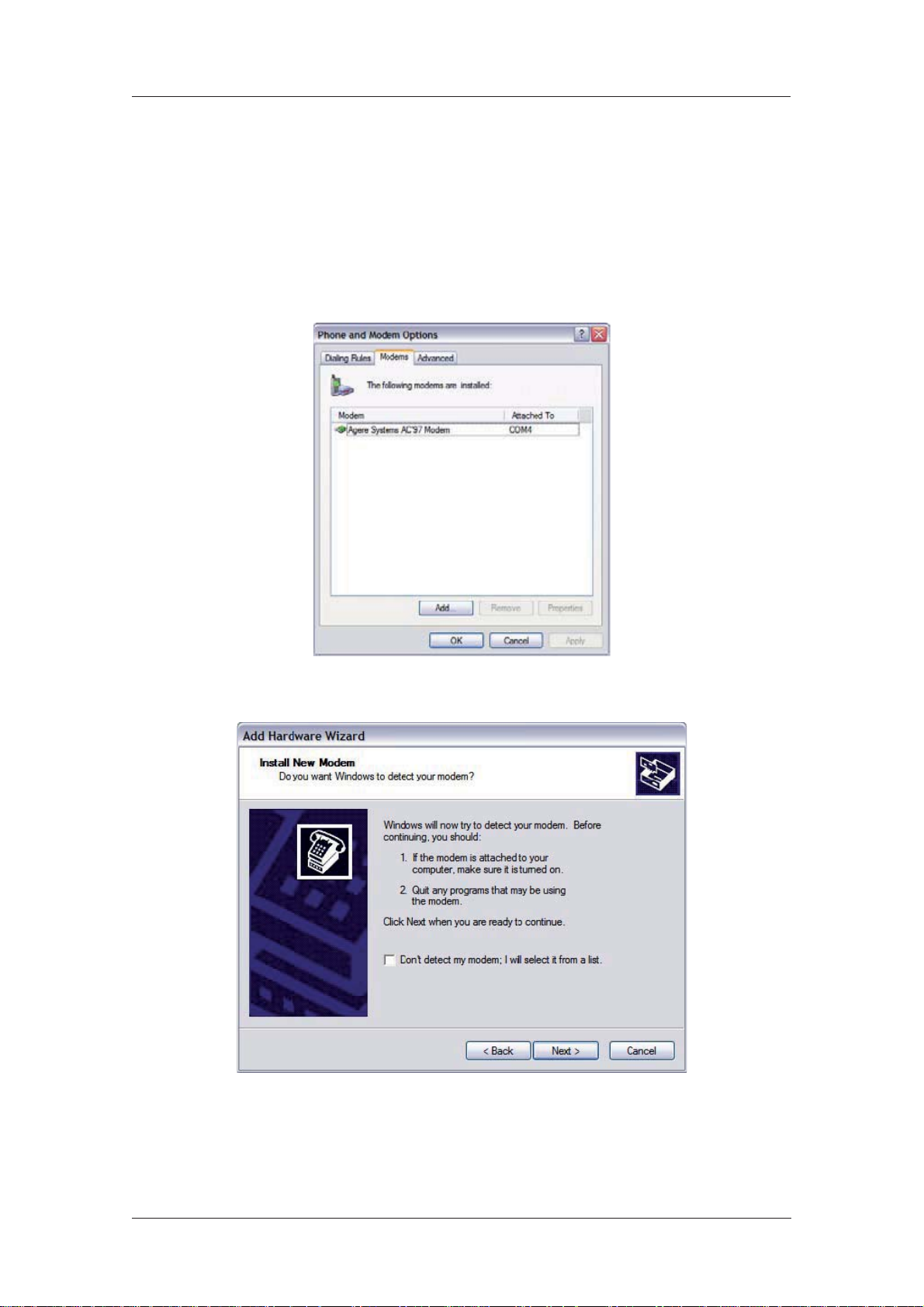
1. Start by selecting Start > Control Panel > Phone and Modem Options. You must be in
Classic View. Select the Modems tab and you will see a dialog similar to the following:
www.westermo.com
2. Click on Add to install a new modem driver:
6622-3201
13
Page 14

www.westermo.com
3. Check the Don’t detect my modem, I will select it from a list option before clicking Next >
to display the following dialog screen:
Web Interface and Command Line Reference Guide
This screen lists the manufacturers and models of modem currently available on your system.
4. Insert the CD supplied into the CD drive and click on Have Disk.
14
6622-3201
Page 15

Web Interface and Command Line Reference Guide
Use the Browse button to locate the Westermo_Multi_Port.inf file on the drive CD supplied
with your unit. This will be in the appropriate Windows version sub-directory of the drives
folder, e.g. win95-98. A list of routers will appear in the Models list:
www.westermo.com
Each entry in the list is the same driver, set up for a different COM port.
5. Choose the entry corresponding to the COM port your router is connected to, and click
Next >. The wizard will ask you which COM port you wish to install the modem on.
6622-3201
15
Page 16
www.westermo.com
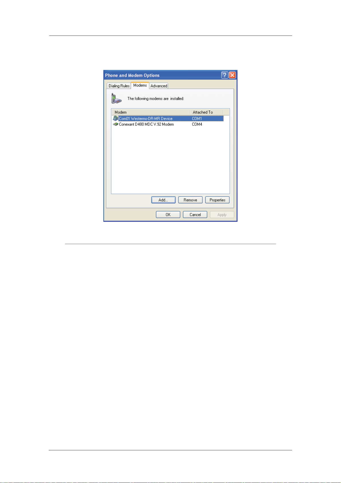
6. Select the appropriate port and click Next >, and Windows will install the driver. Once
installa tion is complete click Finish to return to the Phone and Modem Options dialog, where
your unit will be listed:
Web Interface and Command Line Reference Guide
Click on the OK button if you are satisfied with the installation.
Note:
During the installation you may receive a warning that the driver is not digitally signed. Click on
Con tinue Installation to install the driver.
16
6622-3201
Page 17
Web Interface and Command Line Reference Guide
Creating A New Dial-Up Network Connection 2.2.2
You now need to create a new DUN connection through which you can access your unit.
If you are planning to connect the unit directly to your PC for configuration purposes, connect it to
the appropriate COM port now using a suitable serial cable.
If you wish to configure a remote unit, make sure it is connected to a suitable ISDN line and make a
note of the ISDN number.
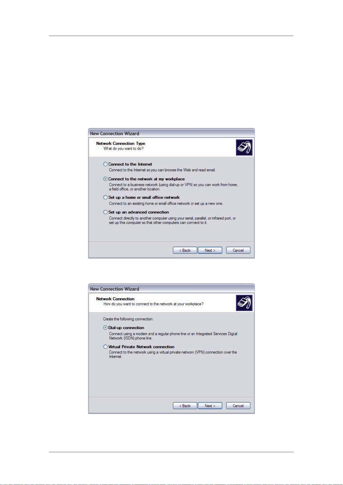
1. From the Windows Start menu, select All Programs > Accessories > Communications >
New Connection Wizard. You will be presented with the New Connection Wizard introduction
screen. Click on Next > to proceed to the Network Connection Type dialog:
www.westermo.com
2. Select the Connect to the network at my workplace radio-button then click on Next >:
6622-3201
17
Page 18

www.westermo.com
3. Select the Dial-up connection radio-button then click on Next >:
Web Interface and Command Line Reference Guide
4. From the Select a Device dialog, select the unit you have just installed and make sure that any
other devices in the list are unchecked. Click Next >.
18
6622-3201
Page 19

Web Interface and Command Line Reference Guide
5. You must now enter a name for the connection. It is helpful to choose a name that you will
easily remember such as “My Local Westermo” or “DR-250 - Bristol Office”. Click Next >. The
fol lowing dialog allows you to fill in the phone number for the connection:
www.westermo.com
If the connection is being created for direct local access using a COM port, you should set the
phone number to 123. This number will be intercepted by the unit and recognised as an attempt
to connect locally.
If the connection is being created for remote access, enter the correct ISDN telephone number
(including the area code) for the remote unit.
When you have done this click Next >. The final dialog screen will confirm that the connection
has been created and includes a check box to allow you to create a shortcut on your desktop if
necessary. Click on Finish to complete the task.
6622-3201
19
Page 20
www.westermo.com
Web Interface and Command Line Reference Guide
Confi guring the New DUN Connection 2.2.3
The new DUN connection that you have just created may now be used to connect to the unit but
before you do this, you will need to check some of the configuration properties.
1. Click on the Start button and select Connect To > My Westermo Router (substituting the
connec tion name you chose).
2. Click on the Properties button to display the properties dialog for the connection:
20
6622-3201
Page 21
Web Interface and Command Line Reference Guide
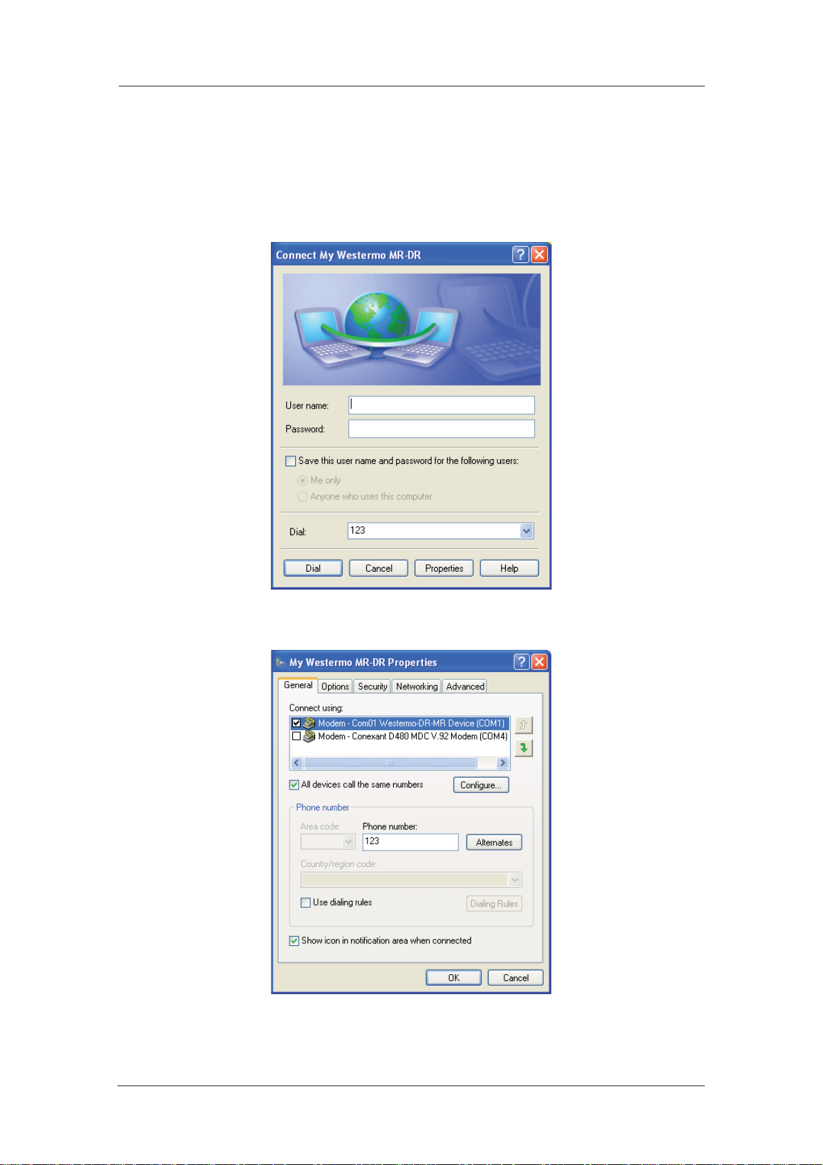
3. On the General tab, click the Configure button to display the Modem Configuration dia log:
Make sure that the Maximum speed (bps): value is set to 115200 and that the Enable hard ware
flow control box is checked.
Click OK when you have finished to return to the main properties dialog.
www.westermo.com
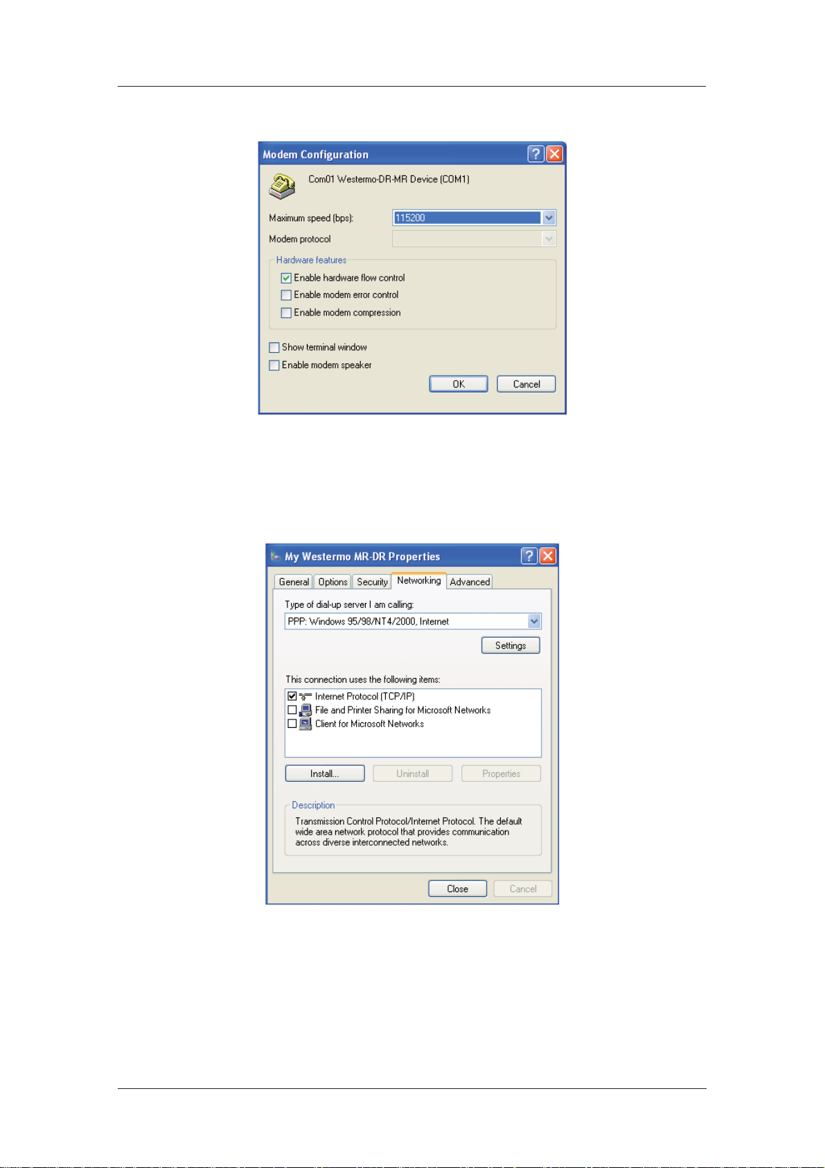
4. Now select the Networking tab:
6622-3201
21
Page 22
www.westermo.com
Web Interface and Command Line Reference Guide
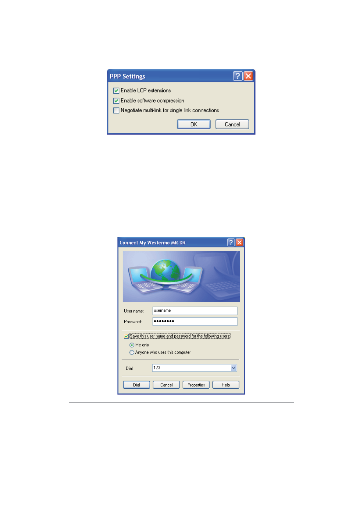
Make sure that the Type of dial-up server I am calling is set to PPP: Windows 95/98/NT/ 2000,
Internet and click on Settings:
Make sure that all three options are unchecked before clicking OK to return to the Network ing
tab. In the This connection uses the following items list, Internet Protocol (TCP/IP) should be
the only item that is checked. Make sure that this is the case and then click OK to return to the
main dialog. You are now ready to initiate a connection.
Initiating a DUN Connection 2.2.4
In the main dialog, you are asked to enter a username and password. The default settings for your
unit are “username” and “password” respectively but you should change as soon as possible in
order to prevent unauthorised access to your unit (refer to the section entitled Configure > Users
for instructions on how to do this). The username is not case sensitive, but the password is.
Note:
When you type the password it will appear as a series of dots to ensure privacy.
Once you have entered these, initiate a connection to your unit by clicking the Dial button. During
the dialling and connection process, you may see a series of status dialog boxes and, if the connection is successful, the final dialog box will indicate that the PPP login has been authenticated.
22
6622-3201
Page 23

Web Interface and Command Line Reference Guide
After a short delay, this dialog will minimise to a “linked computers” icon in the Windows taskbar:
You should now be ready to access the built-in web pages using your Web browser. The default
“web address” for the unit is 1.2.3.4. By default, this is also mapped to the system IP hostname
ss.2000r.
You will need a valid username and password to access the web interface. Once again, the default
settings are username and password respectively. If these values do not allow access, you should
contact your system administrator.
www.westermo.com
6622-3201
23
Page 24

www.westermo.com
Web Interface and Command Line Reference Guide
Using the command line interface3
Using a Web browser to modify text box or table values in the configuration pages is the simplest
way to configure the unit and this process is described in the next chapter. However, if you do not
have access to a Web browser, the unit can be configured using text commands. These commands
may be entered directly at one of the serial ports or via a Telnet session. Remote configuration is
also possible using Telnet or X.25.
To use the serial ports you will need a PC and some communications software such as HyperTerminal™ (supplied with Windows) or TeraTerm™. The same commands may also be used to configure
the unit remotely via Telnet, X.25 or V.120.
There are several types of text command:
AT Commands & S Registers
AT commands (pronounced “ay tee”) and Special registers (S registers) are supported in order
to maintain compatibility with modems when the unit is used as a modem replacement.
Application Commands
Application commands are specific to Westermo products and are used to control most features of the unit when not using the Web interface.
X.3 Commands
These are standard X.3 commands which are used only in X.25 PAD mode
TPAD Commands
These are used only in TPAD mode.
The “AT” Command Interface 3.1
Command Prefi x 3.1.1
The “AT” command prefix is used for those commands that are common to modems. To configure
the unit using AT commands you must first connect it to a suitable asynchronous terminal.
You will first need to set the interface speed/data format for your terminal to 115,200bps, 8 data
bits, no parity and 1 stop bit (these settings can be changed later if necessary).
When your terminal is correctly configured, apply power and wait for the B2 indicator to stop
flashing. Unless you have previously configured the unit to automatically connect to a remote system on power-up, it will now be ready to respond to commands from an attached terminal and is in
“command mode”.
Now type “AT” (in upper or lower case), and press [Enter]. The unit should respond with the message “OK”. This message is issued after successful completion of each command. If an invalid command is entered, the unit will respond with the message “ERROR”.
Note:
For consistency AT commands are shown in upper case throughout this guide.
If there is no response, check that the serial cable is properly connected and that your terminal or
PC communications software is correctly configured before trying again.
If you have local command echo enabled on your terminal, you may see the AT command displayed
as “AATT”. If this happens you may use the “ATE0” command (which will appear as “AATTEE00”),
to prevent the unit from providing command echo. After this command has been entered, further
com mands will be displayed without the echo.
The “AT” command prefix and the commands that follow it can be entered in upper or lower case.
After the prefix, you may enter one or more commands on the same line of up to 40 characters.
When the line is entered, the unit will execute each command in turn.
24
6622-3201
Page 25

Web Interface and Command Line Reference Guide
The Escape Sequence 3.1.2
If you enter a command such as “ATD”, which results in the unit successfully establishing a connection to a remote system, it will issue a “CONNECT” result code and switch from command mode
to on-line mode. This means that it will no longer accept commands from the terminal. Instead, data
will be passed transparently through the unit to the remote system. In the same way, data from the
remote system will pass straight through to your terminal.
The unit will automatically return to command mode if the connection to the remote system is
termi nated. To return to command mode manually, you must enter a special sequence of characters called the “escape sequence”. This consists of three occurrences of the “escape character”, a
pause (user configurable) and then “AT”. The default escape character is “+” so the default escape
sequence is:
+++ {pause} AT
Entering this sequence when the unit is on-line will cause it to return to command mode but it will
NOT disconnect from the remote system unless you specifically instruct it to do so (using “ATH”
or another method of disconnecting). If you have not disconnected the call, the “ATO” command
may be used to go back on-line.
Result Codes 3.1.3
Each time an AT command line is executed, the unit responds with a result code to indicate whether the command was successful. If all commands entered on the line are valid, the “OK” result code
will be issued. If any command on the line is invalid, the “ERROR” result code will be issued.
Result codes may take the form of an English word or phrase (verbose code) or an equivalent
number (numeric code), depending on the setting of the “ATV” command. Verbose codes are used
by default. The “ATV0” command can be used to select numeric codes if required. A full list of the
Result codes is provided in the following table:
www.westermo.com
Numeric Code Verbose Code Meaning
0 OK Command line executed correctly
1 CONNECT ISDN connection established
2 RING Incoming ring signal detected
3 NO CARRIER X.25 service not available
4 ERROR Error in command line
6 NO DIALTONE ISDN service not available
7 BUSY B-channel(s) in use
8 NO ANSWER No response from remote
“S” Registers 3.1.4
“S” (Special) registers are registers in the unit that are used to store certain types of configuration
infor mation. They are essentially a “legacy” feature included to provide compatibility with software
that was originally designed to interact with modems. A full list of the registers is provided under
the section heading “S registers”.
6622-3201
25
Page 26

www.westermo.com
Web Interface and Command Line Reference Guide
Westermo Application Commands 3.2
The unit also supports numerous text-based “application” commands that are specific to Westermo
products and do not require the “AT” prefix. Some of these are generic i.e. they are related to the
general operation of the unit; others are application or protocol specific.
Application commands may be entered via any of the serial ports but if you are using ASY 0 or
ASY 1 with auto-speed detection enabled (which is not possible on ports 2, 3, etc.), you must first
lock the interface speed to the same as that of your terminal. To do this first ensure that the unit is
responding to AT commands correctly and then enter the command:
AT\LS
The speed will remain locked until the unit goes on-line and then off-line again, the power is
removed or the unit is reset. Once the port speed has been locked, “AT” commands will still work
but you may also use the application commands.
Remember that if you subsequently re-enable auto-speed detection on the port it will disable the
use of application commands until the “AT\LS” command has been re-entered or the port speed
has been set to a specific speed using “S31”. For example, to set the port speed at 19,200bps enter
the com mand:
ATS31=6
then change your terminal settings to match.
Note:
Speed locking is not necessary when you use the text commands via a Telnet session.
Westermo application commands (referred to just as text commands throughout the remainder of
this guide), can be entered in upper or lower case but unlike “AT” commands, only one command
may be entered on a line. After each successful command, the “OK” result code will be issued. An
invalid com mand will cause the “ERROR” result code to be issued.
The general syntax for an application commands is:
<cmd_name> <instance> <param_name> <value>
where:
<cmd_name> is the name of the command
<instance> is the instance number for the entity that you are configuring.
<param_name> is the name of the parameter that you wish to configure.
<value> is the new value for the specified parameter.
For example, to set the window size to 5 for X.25 PAD instance 1 you would enter:
pad 1 window 5
Even if there is only once instance of particular entity, you should only enter 0 for the instance
number.
The Reboot Command 3.2.1
The reboot command is used to reboot the unit after altering the configuration. It has three modes
of operation:
reboot - will reboot the unit after any FLASH write operations have been completed. Also, 1
second each is allowed for the following operations to be completed before reboot will take
palce:
IPSec SA delete notifications have been created and sent •
TCP sockets have been closed •
PPP interfaces have been disconnected •
reboot <n> - will reboot the unit in <n> minutes where n is 1 to 65,535
reboot cancel - will cancel a timed reboot if entered before the time period has passed.
26
6622-3201
Page 27

Web Interface and Command Line Reference Guide
The Active Port 3.2.2
When entering “AT” or text commands it is important to understand that in most cases, the command only affects the settings for the “active” port. This is usually the port to which you are physically con nected but you may, if necessary, set the active port to another port of your choice using
the “AT\PORT=N” command where “N” is 0-3.
Establishing a Remote Connection 3.3
Once you have finished configuring the unit, there are several ways of establishing a link to a remote
system:
.
An outgoing V.120 call may be made using the “ATD” command •
You can initiate a DUN session to establish a dial-up PPP connection. •
An outgoing X.25 call may be made using the “ATD” command followed by the X.28 CALL •
command.
An outgoing TPAD (Transaction PAD) call may be made by using the TPAD “a” (address) •
command followed by the appropriate NUA (this is normally only carried out under software control).
Similarly, incoming calls will be handled according to which protocols have been bound to the ASY
ports and whether or not answering is enabled for each protocol.
www.westermo.com
6622-3201
27
Page 28

www.westermo.com
Web Interface and Command Line Reference Guide
Confi guring your unit4
This section describes the various configuration parameters for the unit and how to set or change
them using the built-in web pages or the text commands. Configuration using the Web pages is
achieved by entering the required values into text boxes or tables on the page, or by turning features on or off using checkboxes. The same results can be achieved entering the appropriate text
commands via one of the serial ports.
Note:
The WEB pages are arranged in two tiers. The initial WEB page displayed, is the basis setup
page were many of the most often used features have been grouped together. For more
advanced configuration option the “Full Menu” option can be selected. This will give the user
access to all the advanced features detailed in section 4.4 onwards.
Logging In 4.1
To configure the unit via the Web interface, either establish a DUN connection to it and then open
your web browser and enter 1.2.3.4 for the web address, or enter the unit’s Ethernet IP address
(192.168.0.99) into your web browser after configuring your PC to have an address on the same
sub net. You will be presented with a login page similar to the following:
28
6622-3201
Page 29
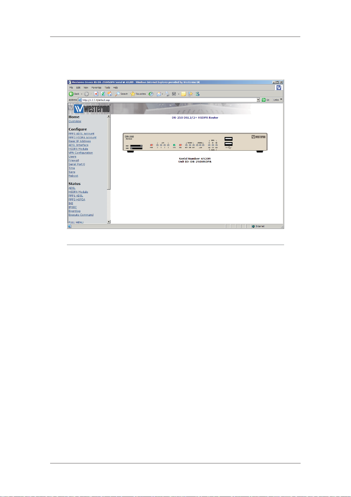
Web Interface and Command Line Reference Guide
The default Username and Password are “username” and “password” respectively. Enter these and
click the Login button to access the configuration pages. The password will be displayed as a series
of dots for security purposes. Correct entry of the username and password will display the main
oper ations page similar to that shown below.
www.westermo.com
Note:
The display the DR-25 Applet, JAVA must first be downloaded, installed and enabled within the
Internet Explorer.
Clicking on the Click to load Applet graphics! button will display a representation of the front panel
of your unit that will be updated every few seconds to show the actual status of the LED indicators.
The model number of your unit will be shown at the top of the screen. The unit’s serial number and
ID are shown below the front panel representation.
Down the left side of the page you will see a directory tree listing the various folders and pages
that are available.
Each folder may be preceded by a small “+” symbol and a closed folder icon indicating that it can
be expanded to reveal sub-pages or folders. To do this, click anywhere on the appropriate line. The
closed folder icon will change to an open folder icon and the “+” symbol will change to “-”. Clicking
on the line again will hide the sub-options. Where there are no sub-pages, a web-page icon is shown
next to the page title. Clicking on this will display the associated web page. The following sections
describe how to use these pages to configure and monitor the operation of your unit.
6622-3201
29
Page 30
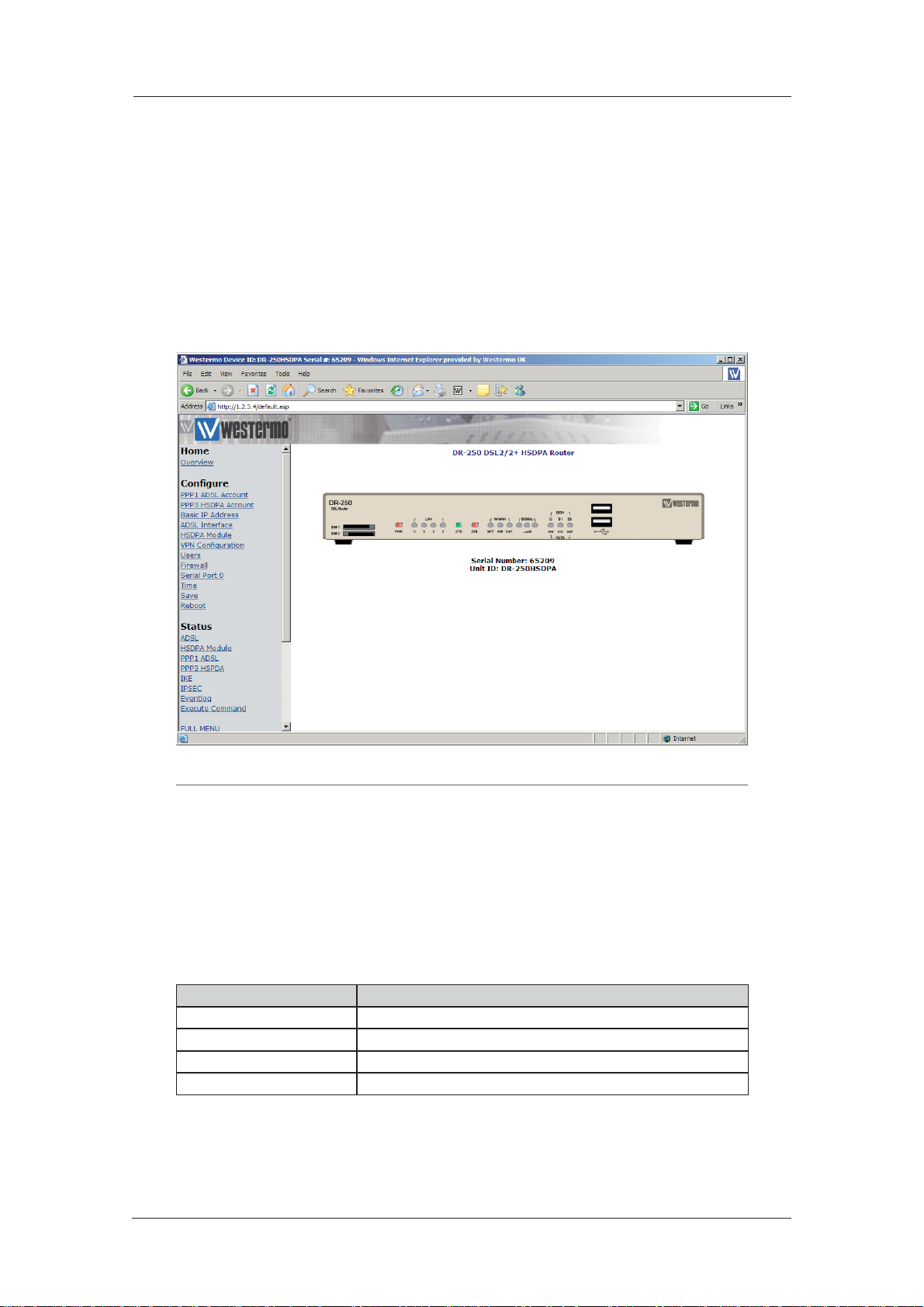
www.westermo.com
Web Interface and Command Line Reference Guide
Confi guring and Testing W-WAN Models 4.2
Refer to the Configure > W-WAN Module section of this guide to configure your router for the
correct APN and PIN code (if any).
You can now power up your unit and test connection to the wireless network. If you have correctly con figured everything, the W-WAN SIM indicator on the front panel should illuminate green
to show that a W-WAN enabled SIM card is present. The unit will now attempt to log on to the
specified GPRS network and if it is able to do so, the W-WAN NET indicator will illuminate steady.
Data passing to and from the network will be reflected by the status of the DAT indicator, which
will flash alternatively red and green. If you are unable to connect to the network, go to the Status
> W-WAN Module web page and press the Refresh button. The page should appear similar to the
following:
Note:
The signal strength is shown in “negative dB”, which means that the stronger the signal, the
lower the number. As a guide -51dB would be a very strong signal, only normally obtained very
close to a cell site. -115dB represents no signal. If your unit reports -115dB try reorienting the
antenna or consider adding an external antenna.
Signal Strength Indicators 4.2.1
On units equipped with GPRS modules, there are three LEDs on the front panel that will indicate
the strength of the signal, as shown in the table below.
LEDs Lit Signal Strength
None Under -113 dBm (effectively no signal)
1 -112 dBm to -87 dBm (weak signal)
2 -86 dBm to -71 dBm (medium strength signal)
3 -70 dBm to -51 dBm (strong signal)
The minimum recommended strength indication is 2 LEDs. If you have no or 1 LEDs lit, it is recommended that you fit an external antenna to the unit.
30
6622-3201
Page 31

Web Interface and Command Line Reference Guide
The Confi guration Pages 4.3
Click on the Configure closed folder icon. The folder will open to show its contents as illustrated
below:
www.westermo.com
You will see a list of web pages and sub-folders containing further web pages. Each page allows
you to configure parameters that are related to a particular function or protocol. For example, the
Ethernet page allows you to set up the unit’s IP address, DNS server address etc.
A page will contain a mixture of text-boxes, check boxes and/or list-boxes. To configure a particular
item simply select the appropriate value from a list, type in into a text-box the appropriate value
from a series of checkboxes.
When you have finished making changes on a particular page, click on the OK button to accept the
changes or CANCEL to revert to the existing values.
Note:
Pressing OK will save the changes you have made for the current session only i.e. they will be
lost if the unit when the power is removed. If you wish to save the changes more permanent,
make sure that you save them to non-volatile memory as described in Saving Configuration
Changes.
The following sections describe each of the configuration pages in detail. They first explain each of
the parameters or options shown on the web page. This is followed by a description of the equivalent text commands.
6622-3201
31
Page 32

www.westermo.com
Web Interface and Command Line Reference Guide
Confi gure > ADAPT > ADAPT n 4.4
The unit incorporates two “Adapt” (rate adaptation protocol) instances. Each instance allows you to
select and configure the protocol to be used for providing rate adaptation over an ISDN B channel.
The supported protocols are V.110, V.120 and X.75. Depending on which protocol is selected, there
may be an associated LAPB instance (distinct from the two general purpose LAPB instances), as for
exam ple, when V.120 is used in error corrected (Multi-frame) mode.
Using the Web Page(s)
V120 mode:
When the V mode parameter (see below), has been set to “V120”, the V120 mode parameter
allows you to select “Unacknowledged”, “Multi-frame” or “Multi-frame/Fallback” mode for V.120
operation.
“Unacknowledged” mode is the simplest mode and does not provide error control.
“Multi-frame” mode provides error control but may only be used if the remote system also sup-
ports this mode. In “Multi-frame/Fallback” mode, the unit will attempt to establish a multi-frame
error controlled link
but will allow a connection in Unacknowledged mode if the remote unit does not support error
control.
MSN:
This parameter provides the filter for the ISDN Multiple Subscriber Numbering facility. It is
blank by default but when set to an appropriate value it will cause the unit to answer only
incoming calls to telephone numbers where the trailing digits match that value (if answering
is enabled). For exam ple setting MSN to 123 will prevent the unit from answering any calls to
numbers that do not end in 123.
Sub-address:
This parameter provides the filter for the ISDN sub-address facility. It is blank by default but
when set to an appropriate value with answering enabled, it will cause the unit to answer
incoming calls only to ISDN numbers where the trailing digits of the sub address called match
that value. For example, setting the Sub-address parameter to 123 will prevent the unit from
answering any calls to numbers where the sub address does not end in 123.
CLI:
Calling Line Identification. The unit will only answer calls from numbers whose trailing digits
match what is entered in this field. The line the unit is connected to must have CLI enabled by
the tele coms provider, and the calling number cannot be withheld.
V mode:
This parameter allows you to specify which rate adaptation protocol to use and can be set to
one of the following:
Option Description
V.120 Mode This allows one B-channel to carry multiple sub-rate channels in a suc-
cession of statistically multiplexed (variable-length) frames. These frames
support error detection and correction procedures if selected under V120
mode (above).
V.110 Mode V.110 is a fixed-frame based rate adaptation standard that subdivides the
ISDN B-channel capacity so that it can carry one lower speed (sub-rate)
data channel.
V110/V120 Detect This mode detects which protocol (V.110 or V.120) the remote host is
using.
X75 Transparent This selects bit transparent X.75 mode of operation.
X75 T.70 NL This option generates T.70 NL telematic prefixes that are required by
some ISDN terminal adapters.
32
6622-3201
Page 33

Web Interface and Command Line Reference Guide
V110 user rate:
This parameter allows you to specify the data rate to be used on ISDN when operating in V.110
mode.
V110 fixed rate:
This parameter can be set to Yes to prevent the V.110 protocol from changing the data rate.
Direct sync mode:
This parameter allows you to replace the standard V120 frame header with the 0xff character.
The data received on the ASY port can then be considered to be written directly onto the sync
ISDN line (apart from the 0xff header in each frame).
Socket mode:
This parameter allows you to connect using a TCP socket rather than an ISDN line.
IP address:
The IP address of the TCP socket the router is connecting to in Socket mode.
IP port:
The port number of the TCP socket the router is connecting to in Socket mode.
www.westermo.com
Listening IP port:
The port number the router is listening on in Socket mode.
LAPB Confi guration:
The following parameters are only used if a V.120 connection is established in Multi-frame mode:
N400 counter:
This is the standard LAPB/LAPD retry counter. The default value is 3 and it should not normally
be necessary to change this.
RR timer (ms):
This is a standard LAPB/LAPD Receiver Ready timer. The default value is 10,000ms (10 seconds)
and it should not normally be necessary to change this.
T1 timer (ms):
This is a standard LAPB/LAPD timer. The default value is 1000 milliseconds and under normal
cir cumstances, it should not be necessary to change it.
T200 timer (ms):
This is a standard LAPB/LAPD re-transmit timer. The default value is 1000 milliseconds and
under normal circumstances, it should not be necessary to change it.
6622-3201
33
Page 34

www.westermo.com
Web Interface and Command Line Reference Guide
Using Text Commands
To configure rate adaptation parameters via the command line use the adaptcommand. To display
current settings for “adapt 0” enter the command:
adapt 0 ?
To change the value of a parameter use the command in the format:
adapt <instance> <parameter> <value>
where <instance> is 0 or 1.
The parameters and values are:
Parameter Values Equivalent Web Parameter
cli number CLI
dial_retries number None - see below
dsync off, on Direct sync mode
fixed_rate off, on V110 fixed rate
ip_addr number IP address
ip_port number IP port
leased_line off, on None - see below
lip_port number Listening IP port
msn number MSN
msnv110 number MSN for V.110
multi 0,1,2 Mode: 0=unacknowledged, 1=multi-frame, 2=multi-frame/fallback
sockmode 0, 1 Socket mode: 0=Off 1=TCP
sub number Sub-address
user_rate 5,6,7,8,9,10,11 V110 User Rate: 5=38400, 6=19200, 7=9600, 8=4800, 9=2400, 10=1200,
11=600
vmode 0,1,2,3,4 V Mode: 0=V120 mode, 1=V110 mode, 2=V110/V120 detect, 3=X75
Transparent, 4=X75 T.70 NL
Dial Retries
If an ISDN connection is established, but rate adaption is not negotiated, this parameter will
allow the unit to drop the connection and redial it.
Leased Line
This parameter will allow the unit to automatically attempt to maintain the connection once it
has been established. A connection can be disconnected by the unit if it is instructed to do so,
but if the connection is lost due to an error, it will continually redial. In other words, if the unit
is not responsi ble for a disconnection, redialling will take place.
To change the values of the LAPB parameters for rate adaptation, use the lapb command. Note
that LAPB 2 is used for “adapt 0” and LAPB 3 is used for “adapt 1”.
34
6622-3201
Page 35

Web Interface and Command Line Reference Guide
Confi gure > Analyser 4.5
Your unit can be configured to maintain a trace of activity taking place at the various ports and of
the layer 2 and 3 protocols. Trace information is stored in a circular buffer in memory. When the
buffer is full, the storage of new trace data starts at the beginning of the buffer again (overwriting
the oldest data). This buffer appears in the file directory as a pseudo-file called “ANA.TXT”.
The following is a typical trace showing activity on the D-channel:
----- 4-5-2002 13:11:50.260 ----- L2 DCHAN SABME from NT to TE: COMMAND POLL SAPI=10, TEI=01,
42,03,7F,
--------- ----- 4-5-2002 13:11:50.260 -----L2 DCHAN UA from TE to NT: RESPONSE FINAL SAPI=10, TEI=01,
42,03,73,
----- 4-5-2002 13:11:50.330 ----- L2 DCHAN I FRAME from NT to TE: COMMAND SAPI=10, TEI=01,
NS=00, NR=00,
42,03,00,00,
X25 RESTART from DCE to DTE:
LCG=0 LCN=0 PTI
10, 00, FB,
07 00 ..
---------
www.westermo.com
----- 4-5-2002 13:11:50.330 -----L2 DCHAN I FRAME from TE to NT: COMMAND SAPI=10, TEI=01, NS=00,
NR=01, 40,03,00,02,
X25 RESTART CONFIRMATION from DTE to DCE:
LCG=0 LCN=0 PTI
10, 00, FF,
Both B and D-channel analysis can be enabled simultaneously if necessary and you can select which
LAPB and LAPD sources you wish to include in the trace by checking the appropriate boxes.
Traffi c capture fi les for use with Ethereal / Wireshark
Depending on the source options chosen, the analyser trace will capture specific traffic into .cap
files. These files can then be opened with Wireshark (formerly Ethereal). The 3 files are stored in
the unit’s memory and will be retained during a warm reboot but cleared in the event of a power
failure.
The .cap files and the traffic captures they contain are:
Capture file name Contents
anaeth.cap Ethernet traffic
anappp.cap PPP traffic
anaip.cap IP traffic
Using the Web Page(s)
The Configure > Analyser web page allows you to turn the analyser “On” or “Off ” and to deter-
mine what information is included in the trace using the following parameters:
Analyser:
This parameter is used to turn the protocol analyser “On” or “Off ”.
6622-3201
35
Page 36

www.westermo.com
Protocol layers:
The check boxes shown under this heading are used to specify which protocol layers are included in the protocol analyser trace. You can choose to generate a trace of the physical layer (Layer
1), the Link Layer (Layer 2) protocol, the Network Layer (Layer 3) protocol or any combination,
by checking or clearing the appropriate check-boxes. In addition, you may select XOT (X.25
over TCP/IP) tracing if this feature is included in your product.
IKE:
This checkbox is used to enable or disable the inclusion of IKE packets in the analyser trace
when using IPSec.
SNAIP:
This checkbox is used to enable or disable the inclusion of SNAIP packets in the analyser trace.
ISDN sources:
The group of check boxes shown under this heading are used to select the ISDN channels (D,
B1 and B2) that will be included in the trace. To include or exclude a specific LAPB or LAPD
instance from the trace ensure that the appropriate checkbox is checked or cleared respectively.
ASY sources:
The group of checkboxes shown under this heading is used to select the ASY ports that will be
included in the trace. To include a trace of commands issued to and responses from a particular port, ensure that the appropriate box is checked. The list of available ports will include the
physical ASY ports, internal “virtual ASY ports” (if present) and ports used by built-in GPRS/
PSTN modems.
Web Interface and Command Line Reference Guide
Raw sync sources:
The group of checkboxes shown under this heading are is to select the synchronous sources
to be included in the trace. These include the ISDN channels D, B1 and B2 and any other synchronous ports/protocols that your unit may include (e.g. physical port 1, 2, etc.). This feature
is especially useful for monitoring data transferred over ISDN when the higher layer protocol
does not record data in the trace (e.g.V.120).
Max I-PAK size:
The text-box labelled Max I-PAK Size allows you to specify the maximum number of bytes from
each X.25 Information Frame that will be included in the trace. Frames that are larger than this
value are truncated. Bear in mind that the larger this value, the quicker the “ANA.TXT” pseudofile (in which the trace output is stored), will become full so that the effective length of the
trace is reduced. The default value of 128 should be suitable in most cases.
PPP sources:
The group of checkboxes shown under this heading may be used to select the PPP sources to
be included in the trace.
IP sources:
The group of checkboxes shown under this heading may be used to select the IP sources to be
included in the trace. These sources include IP packets transmitted over PPP and ETH instances.
Ethernet sources:
The group of checkboxes shown under this heading may be used to select the Ethernet port
sources to be included in the trace.
IP Options:
The Trace Discarded Packets option will trace packets that have been discarded by any interface
and will also record the reason for the discard, regardless of any other analyser trace configuration. Packets blocked by the firewall will also be logged to the trace.
36
6622-3201
Page 37

Web Interface and Command Line Reference Guide
ATM PVC sources:
The group of checkboxes shown under this heading may be used to select the ADSL ATM PVCs
to include in the analyser trace.
IP filters:
This text box is used to prevent the tracing of packets to or from specific TCP or UDP ports.
The format of this text box is a comma-separated list of port numbers. For example, you may
wish to exclude tracing of HTTP traffic that would otherwise swamp the data of interest. This
can be done by entering “80” in the IP Filters box. To filter in specific traffic enter a tilde (~)
symbol before the list of filters, for example to capture telnet and ssh traffic enter ~22,23 in the
Ports filter box.
At the bottom of the page, the OK and Cancel buttons may be used to save or cancel any
changes respectively.
Using Text Commands
From the command line, the ana command can be used to configure the protocol analyser. To display the current settings for the analyser enter the command:
ana <instance> ?
where <instance> is 0 (there is only one instance of the Analyser). To change the value of a
parameter use the same command in the format:
www.westermo.com
ana 0 <parameter> <value>
The parameters and values are:
Parameter Values Equivalent Web Parameter
anon off, on Analyser
asyon 1-15 ASY source
discardson off, on IP Options - Trace discarded pack-
ets
ikeon off, on IKE
ipfilt number list IP filters
l1on off, on Protocol layers - layer 1
l2on off, on Protocol layers - layer 2
l3on off, on Protocol layers - layer 3
lapbon 1-3 ISDN sources - LAPB
lapdon 1-7 ISDN sources - LAPD
maxdata number Max I-PAK size
syon 1-15 Raw sync sources
xoton off, Protocol layers - XOT
For example, to turn the analyser on, enter:
ana 0 anon on
To clear the existing contents of the analyser trace prior to starting a new trace session, use the
following command:
ana 0 anaclr
6622-3201
37
Page 38

www.westermo.com
Web Interface and Command Line Reference Guide
To include or exclude trace information from the various possible sources, use the appropriate
command from the above table in conjunction with the required value from the following tables:
ASY sources:
Value ASY 3 ASY 2 ASY 1 ASY 0
0 OFF OFF OFF OFF
1 OFF OFF OFF ON
2 OFF OFF ON OFF
3 OFF OFF ON ON
4 OFF ON OFF OFF
5 OFF ON OFF ON
6 OFF ON ON OFF
7 OFF ON ON ON
8 ON OFF OFF OFF
9 ON OFF OFF ON
10 ON OFF ON OFF
11 ON OFF ON ON
12 ON ON OFF OFF
13 ON ON OFF ON
14 ON ON ON OFF
15 ON ON ON ON
Ethernet, IP or PPP sources:
These are a special case and cannot be configured from the command line using the ana command.
Instead, these sources must be turned on or off from the command line by using the appropriate
pppor eth commands. For example to turn IP tracing on for PPP instance 1 enter the following
command:
ppp 1 ipanon on
For example to turn PPP tracing on for PPP instance 1 enter the following command:
ppp 1 pppanon on
To turn IP tracing on for Ethernet instance 0 enter the following command:
eth 0 ipanon on
This tracing can also be turned on or off in the web page entries for the Ethernet and PPP instances.
LAPB sources:
Value LAPB 1 LAPB 0
0 OFF OFF
1 OFF ON
2 ON OFF
3 ON ON
38
6622-3201
Page 39

Web Interface and Command Line Reference Guide
LAPD sources:
Value LAPB 2 LAPB 1 LAPB 0
0 OFF OFF OFF
1 OFF OFF ON
2 OFF ON OFF
3 OFF ON ON
4 ON OFF OFF
5 ON OFF ON
6 ON ON OFF
7 ON ON ON
Raw Sync sources:
Value Physical
Por t 1
0 OFF OFF OFF OFF OFF
1 OFF OFF OFF OFF ON
2 OFF OFF OFF ON OFF
3 OFF OFF OFF ON ON
4 OFF OFF ON OFF OFF
5 OFF OFF ON OFF ON
6 OFF OFF ON ON OFF
7 OFF OFF ON ON ON
8 OFF ON OFF OFF OFF
9 OFF ON OFF OFF ON
10 OFF ON OFF ON OFF
11 OFF ON OFF ON ON
12 OFF ON ON OFF OFF
13 OFF ON ON OFF ON
14 OFF ON ON ON OFF
15 OFF ON ON ON ON
16 ON OFF OFF OFF OFF
17 ON OFF OFF OFF ON
18 ON OFF OFF ON OFF
19 ON OFF OFF ON ON
20 ON OFF ON OFF OFF
21 ON OFF ON OFF ON
22 ON OFF ON ON OFF
23 ON OFF ON ON ON
24 ON ON OFF OFF OFF
25 ON ON OFF OFF ON
26 ON ON OFF ON OFF
27 ON ON OFF ON ON
28 ON ON ON OFF OFF
29 ON ON ON OFF ON
30 ON ON ON ON OFF
31 ON ON ON ON ON
Physical
Por t 0
www.westermo.com
ISDN B2 ISDN B1 ISDN D
6622-3201
39
Page 40

www.westermo.com
Web Interface and Command Line Reference Guide
Secondary log fi les
A second analyser trace can be written to a USB flash drive plugged into the router or internal SD
card. This is useful if the analyser is needed to be captured over an extended period of time and the
normal ana.txt file would erase old events before having chance to view them. The secondary log file
can be limited in size if required or allowed to fill the drive. Once the log file is full, old events will
be pruned off the end of the file to allow for new entries at the top.
There are 2 options for this feature:
1. Take a snapshot of the analyser trace on a specific event and append this to the file on the s: or u:
drive.
2. Continuous writing of the analyser trace to both files, i.e. the regular ana.txt and the file on the s:
or u: drive.
Snapshot to log drive
A secondary log file will be created on the USB or drive and the analyser trace will be appended to
this log file on a triggered event. As this is event triggered, there is an option in the logcodes editor
(Con figure > Event Logcodes) Analyser snapshot to log drive which will need to be set to ON for
the event on which the unit will send a copy of the analyser trace to selected drive.
There are no web page options.
The CLI commands are:
To specify the drive to log to:
ana 0 logdrive [s:|u:]
event 0 logdrive [s:|u:]
To specify the log file:
ana 0 logfile <name>
Where <name> is the name of the file on the log drive: For example, to log a trace to the file
u:mylog.txt or s:mylog.txt
ana 0 logfile mylog.txt
To limit the maximum size of the log file:
ana 0 logsizek <n>
Where <n> is the maximum allowed size of the file in Kb, if 0 is used or this value is not set, the
file size is unlimited. For example, to limit the log file to 1Gb
ana 0 logsizek 1048576
40
6622-3201
Page 41

Web Interface and Command Line Reference Guide
Continuous writing
A secondary log file will be created on the log drive and the analyser trace will continuously be
appended to this log file in real time. Care should be taken when using this feature to ensure that
the analyser trace is configured correctly and precisely, to only capture the data that is required. If
the analyser is left to capture all traffic on a fast interface, trace data will be missed out from the file
as the unit is unable to write the data fast enough. If this happens the following error will be seen in
the log file ===== Missed Frames 34 =====
There are no web page options.
The CLI commands are:
To specify the log file:
ana 0 contfile <name>
Where <name> is the name of the file on the log drive:
For example, to log a trace to the file u:analog.txt or s:analog.txt
ana 0 contfile analog.txt
To limit the maximum size of the log file:
ana 0 logsizek <n>
Where <n> is the maximum allowed size of the file in Kb, if 0 is used or this value is not set, the
file size is unlimited. For example, to limit the log file to 1Gb
www.westermo.com
ana 0 logsizek 1048576
Writing PCAP fi les to USB or SD cards
As with the standard analyser trace, the secondary trace may also be configured to capture in
PCAP format for use with Wireshark.
To specify logging to PCAP files:
ana 0 <anatype> <n>
Where <anatype> can be anappps for PPP, anaeths for ethernet and anaips for IP. Where
<n> defines the maximum number of separate log files to create using circular logging.
This is to be used in conjunction with the ana 0 logsizek <n> command to restrict the size
of the log. eg: ana 0 logsizek 524288
The files written to the log drive will be named anapppx, anaethx or anaipx where x will be the
number of the log file. eg: anappp1, anaeth1 or anaip1.
Disable / enable logging
The command logfat <0|1> will disable and enable secondary logging. This can be used to temporarily stop logging to the secondary log files, this does not affect logging to the standard analyser
trace (ana.txt) which is held in internal memory. This command should be used before removing
a USB flash drive to allow the log files to be closed and ensure data is not being written during
removal of the flash drive.
For example, to disable USB logging
logfat 0
To re-enable USB logging
logfat 1
6622-3201
41
Page 42

www.westermo.com
Web Interface and Command Line Reference Guide
Confi gure > ASY Ports > ASY Port n 4.6
Each ASY (serial) port can be independently configured for interface speed, parity, command echo,
etc. These parameters can be set via the appropriate Configure > ASY Port web page or from the
command line using AT commands and S registers.
Using the Web Page(s)
The Configure > ASY Ports folder icon opens to list a page for each of the asynchronous serial
ports (usually ASY 0, 1, 2 & 3).
Note:
On models fitted with GPRS one of the pages will be entitled GPRS port. Similarly, on models
fitted with an analog modem, one of the pages will be entitled PSTN port.
Each page allows you to configure the following port parameters:
Description:
This parameter allows you to enter a name for this Ethernet instance, to make it easier to identify.
Answer ring count (S0):
This parameter controls the answering of incoming V.120 calls. When set to zero, V.120 answering is disabled, otherwise V.120 answering is enabled on this port. The actual value used for this
parameter sets the number of rings the unit will wait before answering. This is equivalent to setting the value of the “S0” register for the relevant ASY port.
DCD:
The DCD parameter is used to configure the way in which the unit controls the DCD signal to
the terminal.
Setting this parameter to “Auto” configures the unit so that it will only turn the DCD signal on
when an ISDN connection has been established (this is equivalent to “AT&C1”).
Selecting “On” configures the unit so that the DCD signal is always on when the unit is powered-up (this is equivalent to “AT&C0”).
Selecting “Off ” configures the unit so that the DCD signal is normally on but goes off for the
length of time specified by S10 after a call is disconnected (this is equivalent to “AT&C2”).
DTR control:
The DTR control parameter is used to configure the way in which the unit responds to the
DTR sig nal from the terminal.
Setting this parameter to “None” configures the unit so that the DTR signal from the attached
ter minal is ignored (this is equivalent to AT&D0).
Selecting to “Drop Call” configures the unit so that it will disconnect the current call and return
to AT command mode when the DTR signal from the terminal goes from on to off (this is
equivalent to “AT&D1”).
Selecting to “Drop Line & Call” configures the unit so that it will disconnect the current call,
drop the line and return to AT command mode when the DTR signal from the terminal goes
from On to Off (this is equivalent to “AT&D2”).
DTR de-bounce time (x20ms):
The value of this parameter determines the length of time (in multiples of 20ms), for which the
DTR signal from the terminal must go off before the unit acts upon any options that are set to
trigger on loss of DTR. Increasing or decreasing this value makes the unit less or more sensitive
to “bounc ing” of the DTR signal respectively.
42
6622-3201
Page 43

Web Interface and Command Line Reference Guide
Echo:
This parameter can be used to turn command echo “On” or “Off” when using the text command interface. Turn command echo off if your terminal provides local command echo itself.
Escape character:
This parameter determines which character is used in the escape sequence. The value of this
parameter is the decimal ASCII code for the character, normally 43 (“+” symbol). Changing this
parameter has the same effect as changing the “S2” register.
Escape delay (x20 ms):
This parameter defines the required minimum length of the pause (in multiples of 20ms), in the
escape sequence between entering three escape characters and then entering “AT”.
Flow control:
The unit supports software flow control using XON/XOFF characters and hardware flow
control using the RS232 RTS and CTS signals. Use this drop-down list to select “Software”,
“Hardware” or a combination of “Both”. To disable flow control select the “None” option.
Interface speed:
This parameter allows you to select the interface speed from a drop down list. Select the
required speed (from 300bps to 115,200bps), or for ASY 0 or ASY 1 only you may select the
“Auto” option to allow automatic speed detection from the AT commands entered at the port.
www.westermo.com
Result codes:
This parameter is used to select “Numeric”, “Verbose” or no result codes (“None”) when using
the text command interface.
Parity:
This parameter is used to set the ASY port parity to “None”, “Odd”, “Even”, “8Data Odd” or
“8Data Even” as required.
Note:
When the ASY port is not in 8-bit with parity mode (i.e. it is in either 8-bit no parity, or 7-bit
with par ity), then the unit will continually check for parity when receiving AT commands, and
adjust and match accordingly.
Disable Port:
This parameter will disable the ASY port from the software stack. The ASY port will not be able
to send data and any data received will be discarded.
Forwarding Timeout(x10ms)
This parameter is the length of time the unit will wait for more data after receiving at least one
byte of data through the serial port and before transmitting it onwards. This timer is reset each
time more data is received. The unit will forward the data onwards when either the forwarding
timer expires or the input buffer is full. This parameter applies to ADAPT, TCPDIAL, TCPPERM
and PANS.
6622-3201
Power-up profile:
This parameter can be set to 0 or 1 to determine which of the two stored profiles is loaded
when the unit is first powered up.
The two buttons at the bottom of the page are used to save/load the above settings to/from
the “SREGS.DAT” file. You may create two stored profiles for each available ASY port containing
the set tings detailed on this page, all of which are contained in “SREGS.DAT”.
Load Profile
Clicking this button loads the profile specified in the list box to the right.
43
Page 44

www.westermo.com
Web Interface and Command Line Reference Guide
Save Profile
Clicking this button will store the current settings to the profile specified in the list box to the
right.
Using Text Commands
ASY ports are configured from the command line using “AT” commands and “S” registers:
Cmd/S-reg Description
E Echo
V Verbose mode
Z Load profile
&C DCD control
&D DTR response
&K Flow control
&W Store profile
&Y Power-up profile
S0 Answer Ring count
S1 Ring count
S2 Escape character
S12 Escape delay
S15 Forwarding register
S23 Parity
S31 ASY port speed
S45 DTR de-bounce time (x10ms)
S99 Disable Port
To save any changes you have made to the profiles in command mode, use the “AT&W” command.
44
6622-3201
Page 45

Web Interface and Command Line Reference Guide
Confi gure > TRANSIP ASY Ports 4.7
TransIP is a method of using virtual ASY ports for serial connections, in effect multiplying the
number of concurrent serial connections to a unit.
Using the Web Page(s)
TransIP #:
The TransIP port number. Each TransIP is assigned a separate virtual ASY port.
ASY port:
The virtual ASY port number assigned to the TransIP instance.
TCP port:
The TCP port number to listen on.
TCP remote port:
TransIP can be configured to actively connect on a TCP socket (i.e. make outgoing socket connections). If this parameter is set it defines the TCP port number to use when TransIP is making
TCP socket connections. When this parameter is set to zero, TransIP is listening only on the
port defined in the TCP Port parameter.
www.westermo.com
Host:
The Hostname or IP address to which TransIP will make outward TCP connections.
Keep Alive(s):
This parameter defines the amount of time (in seconds) a connection will stay open without any
traffic being passed.
Stay connected mode:
When this parameter is set to “On” the socket will not be cleared by the unit) at the end of
a trans action, data call or data session (depending on what the TransIP ASY port was bound to
and pro tocol it was implementing). For example, if the TransIP port is bound to TPAD and this
parameter is “Off ”, then the TransIP TCP socket will be cleared at the end of the TPAD transaction.
Command echo off:
Setting this parameter to “On” disables the command echo for the TransIP port. When set to
“On”, all commands issued will be echoed back in the TransIP TCP socket.
Escape char:
This parameter defines which ASCII character is used as the Escape character, which by default
is the “+” symbol. Entering this character three times followed by a delay of at least the period
defined in the Escape time parameter, and then an AT command will cause the unit to switch
from on-line mode to command mode. This is equivalent to the “S” Register S2.
6622-3201
Escape time:
This parameter defines the delay between sending the escape sequence and entering an AT
com mand for the unit to switch from on-line mode to command mode. This is equivalent to the
“S” Reg ister S12.
45
Page 46

www.westermo.com
Web Interface and Command Line Reference Guide
Using Text Commands
To configure TransIP parameters via the command line use the transipcommand. To display current
settings for a TransIP instance enter the command:
transip <instance> ?
where <instance> is 0 to 3.
To change the value of a parameter use the command in the format:
trnasip <instance> <parameter> <value>
The parameters and values are:
Parameter Values Equivalent Web Parameter
cmd_echo_off off, on Command echo off
escchar character Escape char
esctime number Escape time
host IP address/host name Host
keepact number Keep Alive(s)
port number TCP port
remport number TCP remote port
staycon off, on Stay connected mode
For example, to set TransIP instance 1 to use TCP port 7000 you would enter:
transip 1 port 7000
46
6622-3201
Page 47

Web Interface and Command Line Reference Guide
Confi gure > Backup IP Addresses 4.8
This page contains a table that is used to specify alternative addresses to use when the unit fails in
an attempt to open a socket. These addresses are used only for socket connections that originate
from the unit and are typically used to provide back-up for XOT connections, TANS (TPAD answering) con nections or any application in which the unit is making outgoing socket connections.
When a back-up address is in use, the original IP address that failed to open is tested at intervals to
check if it has become available again. Additionally, at the end of a session, the unit will remember
when an IP address has failed and use the back-up IP address immediately for future connections.
When the original IP address eventually becomes available again, the unit will automatically detect
this and revert to using it.
Using the Web Page(s)
The web page contains a table with four columns headed:
IP Address:
In this column you should enter the original IP address to which the backup address relates.
Backup IP Address: This is the backup address to try when the unit fails to open a connection to
IP Address.
Retry Time (s):
The is the length of time seconds that the unit will wait between checks to see if a connection
can yet be made to IP Address.
Try Next:
In the case that a connection to the primary IP address has just failed, this parameter determines whether a connection to the backup IP address should be attempted immediately or
when the application next attempts to open a connection.
When set to “Yes” the socket will attempt to connect to the backup IP address immediately
after the connection to the primary IP address failed and BEFORE reporting this failure to the
calling application, e.g. TPAD. If the backup is successful this means the application will not experience any kind of failure even though the unit has connected to the backup IP address.
When set to “No” the socket will report the failure to connect back to the calling application imme diately after the connection to the primary IP address has failed. The unit will not
try to connect to the backup IP address at this stage. The next time the application attempts
to connect to the same IP address, the unit will instead automatically connect to the backup IP
address.
www.westermo.com
Chaining IP Addresses
It is possible to chain backup IP addresses by making multiple entries in the table.
For example the following table with 3 rows populated will cause the router to back-up from
192.168.0.1 to 192.168.0.2 and then to 192.168.0.3 and then to 192.168.0.4 (if necessary).
Note:
The length of time that it takes for a connection to an IP address to fail is determined by the
TCP socket connect timeout parameter on the Configure > General web page
6622-3201
47
Page 48

www.westermo.com
Web Interface and Command Line Reference Guide
Confi gure > Basic 4.9
This page contains the parameters to configure Script Basic.
Using the Web Page(s)
User parameter n:
These parameters numbered 1 through 15 are string values that will be used as variables within
the running script, named string1 though string15. For example, configuring User parameter 1 as
test123 will replace all instances of string1 in the Basic script with test123.
Run Basic script:
This is the Basic script that will be run straight away. Only 1 script can be run from this parameter but the running script can call other scripts if required. Click the “Go!” button to run the
Basic script straight away. The “Kill Basic” button will stop the active script from running.
If a Basic script is required to run automatically when the router boots up, this should be done
using the Auto start macro parameter in Configure > General. Enter bas followed by the name
of the script. Eg: bas test.sb
Using Text Commands
To configure Script Basic parameters via the command line use the basic command.
To display current settings for basic 0 enter the command:
basic <instance> ?
where <instance> is 0.
To change the value of a parameter use the command in the format:
basic <instance> <parameter> <value>
The parameters and values are:
Parameter Values Equipment Web Parameter
string1 text User parameter 1
... text ...
string15 text User parameter 15
bas script name Run Basic Script & Go!
basic 0 kill none Kill basic button
48
6622-3201
Page 49

Web Interface and Command Line Reference Guide
Confi gure > BGP 4.10
This page contains the parameters to enable BGP, specify the configuration file and define the action
that is taken on errors or when a new configuration file is loaded. The majority of BGP configuration is done from a text file called bgp.conf This text file can be created in a text editor then
uploaded to the router. A basic example bgp.conf is shown below.
Using the Web Page(s)
Enable BGP:
This parameter enables and disables BGP routing. Options are No, Yes.
Configuration file:
A dropdown list of all the files stored on the router, select the BGP configuration file.
Restart BGP when new config file loaded:
If a new configuration file is selected, BGP can automatically restart and load in the new parameters. Options are No, Yes.
Restart BGP after fatal error:
In the event of a fatal BGP error that stops the process from running, the BGP process will be
restarted automatically. Options are No, Yes.
Debug level:
Enabling this option will output debug information via a CLI session. Options are OFF, LOW,
MEDIUM, HIGH.
www.westermo.com
Using Text Commands
To configure BGP parameters via the command line use the bgp command.
To display current settings for BGP 0 enter the command:
bgp <instance> ?
where <instance> is 0.
To change the value of a parameter use the command in the format:
bgp <instance> <parameter> <value>
The parameters and values are:
Parameter Values Equipment Web Parameter
conffile filename Configuration file
debug 0,1,2,3 Debug level 0=Off 1=LOW
2=MEDIUM 3=HIGH
enable OFF,ON Enable BGP
fatal_rest OFF,ON Restart after fatal error
new_cfg_rest OFF,ON Restart BGP when new config file
loaded
Use of the BGP.conf fi le.
The bgp.conf config file is divided into four main sections.
Macros
User-defined variables may be defined and used later, simplifying the configuration file.
6622-3201
49
Page 50

www.westermo.com
Web Interface and Command Line Reference Guide
Global Confi guration
Global settings for bgp.
Neighbors and Groups
bgp establishes sessions with neighbors. The neighbor definition and properties are set in this section, as well as grouping neighbors for the ease of configuration.
Filter
Filter rules for incoming and outgoing UPDATES. .
Note:
With the exception of macros, the sections should be grouped and appear in bgp.conf in the
order shown above.
Macros
Macros can be defined that will later be expanded in context. Macro names must start with a letter, and may contain letters, digits and underscores. Macro names may not be reserved words (for
example, AS, neighbor, or group). Macros are not expanded inside quotes.
For example:
peer1=”1.2.3.4”
neighbor $peer1 {
remote-as 65001
}
Global Confi guration
There are quite a few settings that affect the operation of the BGP daemon globally.
AS as-number
Set the local autonomous system number to as-number. The AS numbers are assigned by local
RIRs, such as:
AfriNIC for Africa
APNIC for Asia Pacific
ARIN for North America and parts of the Caribbean
LACNIC for Latin America and the Caribbean
RIPE NCC for Europe, the Middle East, and parts of Asia
For example:
AS 65001
sets the local AS to 65001.
fib-update (yes|no)
If set to no, do not update the Forwarding Information Base, a.k.a. the kernel routing table. The
default is yes.
50
6622-3201
Page 51

Web Interface and Command Line Reference Guide
holdtime seconds
Set the holdtime in seconds. The holdtime is reset to its initial value every time either a
KEEPALIVE or an UPDATE message is received from the neighbor. If the holdtime expires the
session is dropped. The default is 90 seconds. Neighboring systems negotiate the holdtime used
when the connection is established in the OPEN messages. Each neighbor announces its configured holdtime; the smaller one is then agreed upon.
holdtime min seconds
The minimal accepted holdtime in seconds. This value must be greater than or equal to 3.
listen on address
Specify the local IP address bgp should listen on.
listen on 127.0.0.1
log updates
Log received and sent updates.
network address/prefix [set ...] network (inet|inet6) static [set ...] network (inet|inet6) connected [set ...] Announce the specified network as belonging to our AS. If set to connected,
routes to directly attached networks will be announced. If set to static, all static routes will be
announced.
network 192.168.7.0/24
It is possible to set default AS path attributes per network statement:
network 192.168.7.0/24 set localpref 220
See also the ATTRIBUTE SET section.
www.westermo.com
nexthop qualify via (bgp|default)
If set to bgp, bgp may use BGP routes to verify nexthops. If set to default, bgp may use the
default route to verify nexthops. By default bgp will only use static routes or routes added by
other routing daemons like ospf.
rde med compare (always|strict)
If set to always, the MED attributes will always be compared. The default is strict, where the
MED is only compared between peers belonging to the same AS.
rde route-age (ignore|evaluate)
If set to evaluate, the best path selection will not only be based on the path attributes but also
on the age of the route, giving preference to the older, typically more stable, route. In this case
the decision process is no longer deterministic. The default is ignore.
route-collector (yes|no)
If set to yes, the route selection process is turned off. The default is no.
router-id address
Set the router ID to the given IP address, which must be local to the machine.
router-id 10.0.0.1
If not given, the BGP ID is determined as the biggest IP address assigned to the local machine.
Neighbors
BGP establishes TCP connections to other BGP speakers called neighbors. Each neighbor is
specified by a neighbor section, which allows properties to be set specifically for that neighbor:
neighbor 10.0.0.2 {
remote-as 65002
descr ”a neighbor”
}
Multiple neighbors can be grouped together by a group section. Each neighbor section within
the group section inherits all properties from its group:
6622-3201
51
Page 52

www.westermo.com
group ”peering AS65002” {
remote-as 65002
neighbor 10.0.0.2 {
descr ”AS65002-p1”
}
neighbor 10.0.0.3 {
descr ”AS65002-p2”
}
}
Instead of the neighbor’s IP address, an address/netmask pair may be given:
neighbor 10.0.0.0/8
In this case, the neighbor specification becomes a template, and if a neighbor connects from
an IP address within the given network, the template is cloned, inheriting everything from the
template but the remote address, which is replaced by the connecting neighbor’s address. With
a template specification it is valid to omit remote-as; bgp will then accept any AS the neighbor
presents in the OPEN message.
There are several neighbor properties:
announce (all|none|self|default-route)
If set to none, no UPDATE messages will be sent to the neighbor. If set to default-route, only
the default route will be announced to the neighbor. If set to all, all generated UPDATE messages will be sent to the neighbor. This is usually used for transit AS’s and IBGP peers. The default
value for EBGP peers is self, which limits the sent UPDATE messages to announcements of the
local AS. The default for IBGP peers is all.
Web Interface and Command Line Reference Guide
announce (IPv4|IPv6) (none|unicast)
For the given address family, control which subsequent address families (at the moment, only
none, which disables the announcement of that address family, and unicast are supported) are
announced during the capabilities negotiation. Only routes for that address family and subsequent address family will be announced and processed.
demote group
Increase the carp(4) demotion counter on the given interface group, usually carp, when the
session is not in state ESTABLISHED. The demotion counter will be increased as soon as bgp
starts and decreased 60 seconds after the session went to state ESTABLISHED. For neighbors added at runtime, the demotion counter is only increased after the session has been
ESTABLISHED at least once before dropping.
depend on interface
The neighbor session will be kept in state IDLE as long as interface reports no link. For carp(4)
interfaces, no link means that the interface is currently backup. This is primarily intended to be
used with carp(4) to reduce failover times.
The state of the network interfaces on the system can be viewed using the show interfaces
command to bgpctl.
descr description
Add a description. The description is used when logging neighbor events, in status reports, for
specifying neighbors, etc., but has no further meaning to bgp.
down
Do not start the session when bgp comes up but stay in IDLE.
dump (all|updates) (in|out) file [timeout]
Do a peer specific MRT dump. Peer specific dumps are limited to all and updates. See also the
dump section in GLOBAL CONFIGURATION.
52
6622-3201
Page 53

Web Interface and Command Line Reference Guide
enforce neighbor-as (yes|no)
If set to yes, AS paths whose leftmost AS is not equal to the remote AS of the neighbor are
rejected and a NOTIFICATION is sent back. The default value for IBGP peers is no otherwise
the default is yes.
holdtime seconds
Set the holdtime in seconds. Inherited from the global configuration if not given.
holdtime min seconds
Set the minimal acceptable holdtime. Inherited from the global configuration if not given.
ipsec (ah|esp) (in|out) spi spi-number authspec [encspec]
Enable IPsec with static keying. There must be at least two ipsec statements per peer with man-
ual keying, one per direction. authspec specifies the authentication algorithm and key. It can be
sha1 <key>
md5 <key>
encspec specifies the encryption algorithm and key. ah does not support encryption. With esp,
encryption is optional. encspec can be
3des <key>
3des-cbc <key>
aes <key>
aes-128-cbc <key>
www.westermo.com
Keys must be given in hexadecimal format.
ipsec (ah|esp) ike
Enable IPsec with dynamic keying. In this mode, bgp sets up the flows, and a key management
daemon such as isakmp is responsible for managing the session keys. With isakmpd, it is sufficient to copy the peer’s public key, found in /etc/isakmpd/private/local.pub, to the local machine.
It must be stored in a file named after the peer’s IP address and must be stored in /etc/
isakmpd/pubkeys/ipv4/. The local public key must be copied to the peer in the same way. As
bgp manages the flows on its own, it is sufficient to restrict isakmpd to only take care of keying
by specifying the flags -Ka. This can be done in rc.conf.local. After starting the isakmpd and bgp
daemons on both sides, the session should be established.
local-address address
When bgp initiates the TCP connection to the neighbor system, it normally does not bind to a
specific IP address. If a local address is given, bgp binds to this address first.
max-prefix number [restart number]
Terminate the session after number prefixes have been received (no such limit is imposed by
default). If restart is specified, the session will be restarted after number minutes.
multihop hops
Neighbors not in the same AS as the local bgp normally have to be directly connected to the
local machine. If this is not the case, the multihop statement defines the maximum hops the
neighbor may be away.
passive
Do not attempt to actively open a TCP connection to the neighbor system.
6622-3201
remote-as as-number
Set the AS number of the remote system.
route-reflector [address]
Act as an RFC 2796 route-reflector for this neighbor. An optional cluster ID can be specified;
otherwise the BGP ID will be used.
53
Page 54

www.westermo.com
set attribute ...
Set the AS path attributes to some default per neighbor or group block:
set localpref 300
See also the ATTRIBUTE SET section. Set parameters are applied to the received prefixes; the
only exceptions are prepend-self, nexthop no-modify and nexthop self. These sets are rewritten
into filter rules and can be viewed with ``bgp -nv’’.
softreconfig (in|out) (yes|no)
Turn soft reconfiguration on or off for the specified direction. If soft reconfiguration is turned
on, filter changes will be applied on configuration reloads. If turned off, a BGP session needs to
be cleared to apply the filter changes. Enabling softreconfig in will raise the memory requirements of bgp because the unmodified AS path attributes need to be stored as well.
tcp md5sig password secret
tcp md5sig key secret Enable TCP MD5 signatures per RFC 2385. The shared secret can either
be given as a password or hexadecimal key.
tcp md5sig password mekmidasdigoat
tcp md5sig key deadbeef
ttl-security (yes|no)
Enable or disable ttl-security. When enabled, outgoing packets are sent using a TTL of 255 and a
check is made against an incoming packet’s TTL. For directly connected peers, incoming packets
are required to have a TTL of 255, ensuring they have not been routed. For multihop peers,
incoming packets are required to have a TTL of 256 minus multihop distance, ensuring they have
not passed through more than the expected number of hops. The default is no.
Web Interface and Command Line Reference Guide
Filter
BGP has the ability to allow and deny UPDATES based on prefix or AS path attributes. In addi-
tion, UPDATES may also be modified by filter rules. For each UPDATE processed by the filter,
the filter rules are evaluated in sequential order, from first to last. The last matching allow or
deny rule decides what action is taken.
The following actions can be used in the filter:
allow The UPDATE is passed.
deny The UPDATE is blocked.
match Apply the filter attribute set without influencing the filter decision.
PARAMETERS
The rule parameters specify the UPDATES to which a rule applies. An UPDATE always comes
from, or goes to, one neighbor. Most parameters are optional, but each can appear at most
once per rule. If a parameter is specified, the rule only applies to packets with matching
attributes.
as-type as-number
This rule applies only to UPDATES where the AS path matches. The as-number is matched
against a part of the AS path specified by the as-type. as-type is one of the following operators:
AS (any part)
source-as (rightmost AS number)
transit-as (all but the rightmost AS number)
Multiple as-number entries for a given type or as-type as-number entries may also be specified,
separated by commas or whitespace, if enclosed in curly brackets:
deny from any AS { 1, 2, 3 }
deny from any { AS 1, source-as 2, transit-as 3 }
deny from any { AS { 1, 2, 3 }, source-as 4, transit-as 5 }
54
6622-3201
Page 55

Web Interface and Command Line Reference Guide
community as-number:local
community name
This rule applies only to UPDATES where the community path attribute is present and matches.
Communities are specified as as-number:local, where as-number is an AS number and local is a
locally significant number between zero and 65535. Both as-number and local may be set to `*’
to do wildcard matching. Alternatively, well-known communities may be given by name instead
and include NO_EXPORT, NO_ADVERTISE, NO_EXPORT_SUBCONFED, and NO_PEER.
Both as number and local may be set to neighbor-as, which is expanded to the current neighbor
remote AS number.
www.westermo.com
6622-3201
55
Page 56

www.westermo.com
(from|to) peer
This rule applies only to UPDATES coming from, or going to, this particular neighbor. This
parameter must be specified. peer is one of the following:
any Any neighbor will be matched.
address Neighbors with this address will be matched.
group descr Neighbors in this group will be matched.
Multiple peer entries may also be specified, separated by commas or whitespace, if enclosed in
curly brackets:
deny from { 128.251.16.1, 251.128.16.2, group hojo }
prefix address/len
This rule applies only to UPDATES for the specified prefix.
Multiple address/len entries may be specified, separated by commas or whitespace, if enclosed in
curly brackets:
deny from any prefix { 192.168.0.0/16, 10.0.0.0/8 }
Multiple lists can also be specified, which is useful for macro expansion:
good=”{ 192.168.0.0/16, 172.16.0.0/12, 10.0.0.0/8 }”
bad=”{ 224.0.0.0/4, 240.0.0.0/4 }”
ugly=”{ 127.0.0.1/8, 169.254.0.0/16 }”
deny from any prefix { $good $bad $ugly }
prefixlen range
This rule applies only to UPDATES for prefixes where the prefixlen matches. Prefix length
ranges are specified by using these operators:
= (equal)
!= (unequal)
< (less than)
<= (less than or equal)
> (greater than)
>= (greater than or equal)
- (range including boundaries)
>< (except range)
Web Interface and Command Line Reference Guide
>< and - are binary operators (they take two arguments). For instance, to match all prefix
lengths >= 8 and <= 12, and hence the CIDR netmasks 8, 9, 10, 11 and 12:
prefixlen 8-12
Or, to match all prefix lengths < 8 or > 12, and hence the CIDR netmasks 0-7 and 13-32:
prefixlen 8><12
prefixlen can be used together with prefix. This will match all prefixes in the 10.0.0.0/8 netblock
with net masks longer than 16:
prefix 10.0.0.0/8 prefixlen > 16
quick
If an UPDATE matches a rule which has the quick option set, this rule is considered the last
matching rule, and evaluation of subsequent rules is skipped.
set attribute ...
All matching rules can set the AS path attributes to some default. The set of every matching
rule is applied, not only the last matching one. See also the following section.
ATTRIBUTE SET AS path attributes can be modified with set.set can be used on network statements, in neighbor or group blocks, and on filter rules. Attribute sets can be expressed as lists.
The following attributes can be modified:
community [delete] as-number:local
community [delete] name
Set or delete the COMMUNITIES AS path attribute. Communities are specified as
56
6622-3201
Page 57

Web Interface and Command Line Reference Guide
as number:local, where as-number is an AS number and local is a locally-significant number
between zero and 65535. Alternately, well-known communities may be specified by name:
NO_EXPORT, NO_ADVERTISE, NO_EXPORT_SUBCONFED, or NO_PEER.
localpref number
Set the LOCAL_PREF AS path attribute. If number starts with a plus or minus sign, LOCAL_
PREF will be adjusted by adding or subtracting number; otherwise it will be set to number.
med number
metric number
Set the MULTI_EXIT_DISC AS path attribute. If number starts with a plus or minus sign,
MULTI_EXIT_DISC will be adjusted by adding or subtracting number; otherwise it will be set to
number.
nexthop (address|blackhole|reject|self|no-modify)
Set the NEXTHOP AS path attribute to a different nexthop address or use blackhole or reject
routes. If set to no-modify, the nexthop attribute is not modified. Unless set to self, the nexthop
is left unmodified for IBGP sessions. self forces the nexthop to be set to the local interface
address.
set nexthop 192.168.0.1
set nexthop blackhole
set nexthop reject
set nexthop no-modify
set nexthop self
www.westermo.com
pftable table
Add the prefix in the update to the specified pf(4) table, regardless of whether or not the path
was selected for routing. This option may be useful in building realtime blacklists.
prepend-neighbor number
Prepend the neighbor’s AS number times to the AS path.
prepend-self number
Prepend the local AS number times to the AS path.
rtlabel label
Add the prefix with the specified label to the kernel routing table.
weight number
The weight is used to tip prefixes with equally long AS paths in one or the other direction. A
prefix is weighed at a very late stage in the decision process. If number starts with a plus or
minus sign, the weight will be adjusted by adding or subtracting number; otherwise it will be set
to number. Weight is a local non-transitive attribute and a bgp-specific extension.
Example bgp.conf
# sample bgp configuration file
#macros
peer1=”100.100.100.23”
# global configuration
AS 65001
router-id 100.100.100.20
holdtime 180
holdtime min 3
# fib-update no
# route-collector no
log updates
network inet static
network inet connected
neighbor 100.100.100.23 {
6622-3201
57
Page 58

www.westermo.com
remote-as65003
descrupstream
multihop2
passive
announceall
}
neighbor 100.100.100.27 {
remote-as65003
descr”site a”
multihop2
passive
announceall
}
neighbor 100.100.102.28 {
remote-as65003
descr”site b”
multihop2
passive
announceall
}
# filter out prefixes longer than 24 or shorter than 8 bits
#deny from any
#allow from any prefixlen 8 - 24
# do not accept a default route
#allow from any prefix 0.0.0.0/0
# filter bogus networks
#deny from any prefix 10.0.0.0/8 prefixlen >= 8
#deny from any prefix 172.16.0.0/12 prefixlen >= 12
#deny from any prefix 192.168.0.0/16 prefixlen >= 16
#deny from any prefix 169.254.0.0/16 prefixlen >= 16
#deny from any prefix 192.0.2.0/24 prefixlen >= 24
#deny from any prefix 224.0.0.0/4 prefixlen >= 4
#deny from any prefix 240.0.0.0/4 prefixlen >= 4
Web Interface and Command Line Reference Guide
58
6622-3201
Page 59

Web Interface and Command Line Reference Guide
Confi gure > Certifi cates > Certifi cate request 4.11
The unit can establish an IPSec tunnel to another unit using certificates. For more information on
using certificates with your unit, please refer to the Application Note “How to configure an IPSEC
VPN tunnel between two Westermo Routers using Certificates and SCEP”, which is available from
the Westermo technical support.
This page contains fields that required when sending a certificate request to a Certificate Authority
(CA). This information forms part of the certificate request, and thus part of the signed public key
certificate.
Using the Web Page(s)
Challenge password:
Before you can create a certificate request you must first obtain a challenge password from the
Certificate Authority Server. This password is generally obtained from the SCEP CA server by
way of a WEB server, or a phone call to the CA Server Administrator. For the Microsoft® SCEP
server, you browse to a web interface. If the server requires a challenge password, it will be displayed on the page along with the CA certificate fingerprint.
This challenge password is usually only valid once and for a short period of time, in this case 60
minutes, meaning that a certificate request must be created after retrieving the challenge password.
Country:
A two-character representation of the country the unit is in (e.g. UK for the United Kingdom).
Common name:
Enter a name for your unit. This field is important, as the common name will be used as the
unit’s ID in IKE negotiations.
Locality:
The location of the unit (e.g. London).
Organisation:
An appropriate company name.
Organisational unit:
An appropriate organisational unit within the company (e.g. Development).
State:
State, County of Province the unit is located in.
Email address:
An appropriate email address.
Unstructured name:
This parameter is optional. You can enter some descriptive text if you wish.
Digest algorithm:
Choose either MD5 or SHA1. This is used when signing (encrypting) the certificate request.
www.westermo.com
6622-3201
59
Page 60

www.westermo.com
Web Interface and Command Line Reference Guide
Using Text Commands
From the command line, the creq command can be used to enter the certificate request information. To display the current settings for certificate request enter the command:
creq <instance> ?
where <instance> is 0. To change the value of a parameter use the same command in the format:
creq <instance> <parameter> <value>
where <instance> is 0.
The parameters and values are:
Parameter Values Equivalent Web Parameter
challenge_pwd text Challenge password
commonname text Common name
country text Country
digest text Digest algorithm
email text Email
locality text Locality
orgname text Organisation
org_unit text Organisational unit
state text State
unstructname text Unstructured name
For example, to set the country as UK, enter:
creq 0 country UK
To set the email address, enter:
creq 0 email someone@hotmail.com
60
6622-3201
Page 61

Web Interface and Command Line Reference Guide
Confi gure > Certifi cates > SCEP 4.12
This page contains information needed to both request CA certificates from the CA server, and to
enrol the certificate requests using Simple Certificate Enrolment Protocol (SCEP).
Using the Web Page(s)
Host:
The IP address of the CA server.
Remote port:
The destination port. If this parameter is non-zero, the unit will use this value as the destination
port rather than the default of 80 (HTTP).
Path:
The path on the server to the SCEP application. The path will be entered automatically if you
choose either cgi-bin or Microsoft SCEP from the drop-down list.
Application:
This represents the SCEP application on the server.
CA Identifier:
CA identifier.
Private key filename:
The filename of the private key.
Certificate request filename:
The filename of the certificate request.
Certificate filename:
The filename for the public key certificate (must be prefixed with “cert”)
CA certificate filename:
The filename of the CA certificate.
CA encryption certificate filename:
The filename of the CA encryption certificate.
CA signature certificate filename:
The filename of the CA signature certificate.
CA certificate filename prefix:
Prefix used for all CA certificates.
www.westermo.com
There are also two buttons at the bottom of the page:
Enrol Certificate Request
Clicking this button will send the certificate request to the CA for signing.
Get CA certificate/s
Clicking this button will retrieve the CA certificates from the CA server.
6622-3201
61
Page 62

www.westermo.com
Web Interface and Command Line Reference Guide
Using Text Commands
From the command line, the scep command can be used to retrieve CA certificates and enrol
certif icate requests.
To display the current settings for SCEP enter the command:
scep <instance> ?
where <instance> is 0.
To change the value of a parameter use the same command in the format:
scep <instance> <parameter> <value>
where <instance> is 0. The parameters and values are:
Parameter Value Equivalent Web Parameter
app text Application
caencfile text CA encryption certificate filename
cafile text CA certificate filename
caident text CA Identifier
casigfile text CA signature certificate filename
certfile text Certificate filename
host text Host
keyfile text Private Key filename
path text Path
port number Remote port
reqfile text Certificate request filename
For example, to enter the path for Microsoft SCEP, enter:
scep 0 path certsrv/mscep/mscep.dll
To set the port to port 20, enter:
scep 0 port 20
62
6622-3201
Page 63

Web Interface and Command Line Reference Guide
Confi gure > Certifi cates > Utilities 4.13
This page contains information used to generate the private key needed before a certificate can be
requested from the CA.
Using the Web Page(s)
New Key Size:
The size of the private key in bits. If this parameter is set to Off, the private key will not be
gener ated. The key size can be anything between 384 bits and 2048 bits. The larger the key, the
more secure the connection, but also the larger the key, the slower the connection.
Private key filename:
Enter a name for the private key (the filename must be prefixed with “priv” and have a “.pem”
extension).
Save in SSHv1 format:
If this box is checked the private key will be generated in SSH version 1 format. If this box is
cleared the private key will be generated in SSH version 2 format.
Note:
IPSec requires SSH version 2 private keys.
www.westermo.com
Certificate request filename:
Enter a name for the certificate request (the filename must have a “.pem” extension)
The two buttons at the bottom of the page are used to generate the private key and the certifi-
cate request.
Generate Private Key
Clicking this button will generate the private key.
Generate Certificate Request
Clicking this button will generate the certificate request. If the private key does not already
exist, and the appropriate fields are completed, the key will be generated at the same time.
6622-3201
63
Page 64

www.westermo.com
Web Interface and Command Line Reference Guide
Using Text Commands
From the command line the genkey command can be used to generate a private key. To generate a
private key, enter the command
genkey <instance> <keysize> <filename> < -ssh1>
where: <instance> is 0
<keysize> is the size of the key in bits
<filename> is the name of the private key file
<-ssh1> is optional, and will generate the private key file in SSH version 1 format
For example, to generate a 1024 bit SSH version 2 key called privkey.pem, enter:
genkey 1024 privkey.pem
You will see the following output:
OK
Starting 1024 bit key generation. Please wait. This may take some
time...
\Key generated, saving to FLASH file privkey.pem
Closing file
Private key file created
All tasks completed
From the command line, the creqnew command can be used to generate a certificate request. If the
private key does not already exist, and the appropriate parameters are entered, the key will be generated at the same time.
To generate a certificate request, enter the command:
creq new <parameter><value> <parameter><value>
To generate a private key and a certificate request, enter the command:
creq new <parameter><value> <parameter><value> <parameter><value>
The parameters and values are:
Parameter Values Equivalent Web Parameter
-b number New Key Size
-k text Private key filename
-o text Certificate request filename
For example, to generate a certificate request file called “request.pem” from a private key called
“priv001.pem”, enter:
creq new -kpriv001.pem -o request.pem
To generate a 512 bit private key called “private.pem”, and generate a certificate request called “certreq.pem” using that file, enter:
creq new -b512 -kprivate.pem -ocertreq.pem
Private key fi les - Splitting Certifi cates
For increased security there is the option of splitting the private key file between the Westermo
flash and a USB memory stick. Once a private key has been split and stored in 2 parts, the USB
memory stick must be present for any successful IKE negotiations that involve the private key. As
the USB memory only contains a part of the private key, it cannot be used in another unit.
The command to split a private key is:
privsplit <certificate filename>
64
6622-3201
Page 65

Web Interface and Command Line Reference Guide
Confi gure > Calling Numbers 4.14
Note:
This feature is for use by experienced personnel for network testing and fault diagnosis. It
should not be required in normal use. To use this feature, your ISDN circuit must support the
Calling Line Identi fication (CLI) facility. If CLI is available, incoming calls from specified numbers
may be answered nor mally or alternatively, rejected with an optional reject code.
Using the Web Page(s)
The Configure > Calling Numbers page contains a table that allows you to enter a series of tele-
phone numbers each of which has an associated Answer or Reject parameter, and in the case of
num bers from which calls are to be rejected, a user defined reason code. For each number that
you enter and set to “Reject”, the unit will reject incoming calls from that number using the reject
reason code specified. The reason code is simply a numeric value that may be selected to suit your
particular appli cation. If any one of the entries is set to “Answer” the unit will only answer incoming
calls from that number and will reject calls from other numbers using a standard ISDN reject code.
Using Text Commands
www.westermo.com
To configure calling numbers from the command line use the rejlst command. To display an entry in
the calling numbers list enter the command:
rejlst <entry> ?
where <entry> is 0-9.
For example, to display entry number 5 enter the command:
rejlst 5 ?
Up to three separate commands are needed to set up an entry. These take the form:
rejlst <entry> NUM <number>
rejlst <entry> ANS <mode>
rejlst <entry> CODE <code>
where: <entry> is the required entry number in the calling numbers table in each case.
<number> is the telephone number.
<mode> is either Off to reject calls from the corresponding number (the default), or On to accept
calls.
<code> is the reject reason code.
For example:
rejlst 0 NUM 1234567
rejlst 0 ANS OFF
rejlst 0 CODE 42
6622-3201
65
Page 66

www.westermo.com
Web Interface and Command Line Reference Guide
Confi gure > Command Filters 4.15
When this feature is enabled, commands will not reach the unit’s command interpreter unless they
are defined in the Command Filters table. Terminal devices may send commands that the unit will
not nec essarily understand but that require a basic “OK” response.
With Command Filtering turned on any command entered will be responded to with a modem like
“OK” response unless the command is found in the Command Filters table. The command filter
table uses wildcharacter matching so that command filters such as “cmd*” are permitted which
would allow all “cmd 0 ....” commands to be executed. Note that the command mapping table is
checked first and the command filter table is only checked if there was not a match in the command mapping table.
Using the Web Page(s)
The Configure > Command Filters page contains a table that allows you to enter a series of com-
mand filters.
Using Text Commands
To enable or disable command filtering, use the cmd command in the format:
cmd <port> cfilton <value>
where: <port> is the port number
<value> is 1 to enable command filtering, or 0 to disable command filtering
To configure command filters from the command line use the cfilter command. To display an entry
in the command filter list enter the command:
cfilter <entry> ?
where <entry> is 0-9.
For example, to display entry number 5 enter the command:
cfilter 5 ?
To change the value of a parameter use the same command in the format:
cfilter <entry> cmd <value>
where:
<entry> is the required entry number in the command filters table
<value> is the command.
Note:
If the command string contains blank characters you must enclose it with double quotes. When
sub stituting a command, upper case characters are considered the same as the corresponding
lower case characters.
66
6622-3201
Page 67

Web Interface and Command Line Reference Guide
Confi gure > Command Mappings 4.16
It is possible to specify a small number of command “aliases” on your unit. This allows you to specify
substitute strings for text commands entered at the command line.
Using the Web Page(s)
The Configure > Command Mappings page contains a table that allows you to specify up to four
ali ases for commands entered at the command prompt. Each table entry has the following fields:
Command to Map:
This column specifies the command that you want substituted.
Command Mapping:
This column specifies the corresponding replacement command.
Using Text Commands
From the command line, use the cmd command to configure or display the command mappings. To
display the current command mappings enter the following commands:
www.westermo.com
cmd <n> cmdmapo ?
cmd <n> cmdmapi ?
where <n> is the table entry number, i.e. 0 to 3. The cmdmapi parameter shows the command to
be substituted, and the cmdmapo parameter shows the replacement command.
To change a command mapping use the following commands:
cmd <n> cmdmapo <string>
cmd <n> cmdmapi <string>
Note:
If either string contains blank characters you must enclose it with double quotes. When substituting a command, upper case characters are considered the same as the corresponding lower
case characters.
For example, to substitute the command “type ana.text” with “tana”, use the commands:
cmd 0 cmdmapo “type ana.txt”
cmd 0 cmdmapi tana
After you have done this, typing “tana” at the command line will have the same effect as typing
“type ana.txt”.
6622-3201
67
Page 68

www.westermo.com
Web Interface and Command Line Reference Guide
Confi gure > DHCP Servers > Ethernet Port n 4.17
Westermo routers incorporate one or more Dynamic Host Configuration Protocol (DHCP) servers, one for each Ethernet port. DHCP is a standard Internet protocol that allows a DHCP server
to dynamically distribute IP addressing and configuration information to network clients.
The Configure > DHCP Servers folder contains one page for each for the DHCP Server instances.
In addition, there is a separate page for mapping MAC addresses to fixed IP addresses.
Using the Web Page(s)
The Configure > DHCP Servers pages allow you to set up the parameters for the DHCP servers.
The parameters are as follows.
Forward requests to this server (Act as relay agent):
Use this parameter if the DHCP server is on a different subnet. Entering an IP address will forward DHCP requests to the IP address specified. DHCP server must be within 4 hops.
Minimum assigned IP address:
This parameter specifies the lowest IP address that the DHCP server will assign to a client.
Clearing this parameter will disable the DHCP server. This may be necessary if another device
on the LAN provides a DHCP server.
IP address range:
This parameter is used to specify the number of different IP addresses that the DHCP server
will assign. A value of 10 would assign 10 addresses starting with the address set for the
Minimum assigned IP address parameter.
Minimum assigned IP address #2 & #3:
As above, but if using pools 2 & 3 this allows for breaks in the DHCP scope. eg DHCP pool 1
172.16.1.1 - 10, DHCP pool 2 172.16.1.21 - 99. Leaving 172.16.1.11 -20 free for static IP
addresses.
1 - Mask:
This parameter specifies the subnet mask used on the network to which the unit is connected.
For example, for a Class C network this would be 255.255.255.0.
3 - Gateway address:
A “gateway” is required in order to route data to IP addresses that are not on the local subnet.
This parameter specifies the IP address of the gateway (which is usually the IP address of the
router itself as configured by the IP address parameter on the Configure > Ethernet > ETH n
page). Alternatively, you may set this to the address of another router on the LAN.
6 - DNS server address:
This parameter specifies the IP address of the primary DNS server to be used by clients on
the LAN. This will usually be the IP address of the unit itself (as configured by the Configure >
Ethernet > ETH n IP address parameter). Alternatively, you may set this to the address of an
alternative DNS server.
6 - Secondary DNS server address:
This parameter specifies the IP address of a secondary DNS server (if available) to be used by
clients on the LAN.
15 - Domain name:
This is the domain name which will be returned to clients. Altered DNS so that queries for
names using that domain.
68
6622-3201
Page 69

Web Interface and Command Line Reference Guide
44 - NetBIOS name server address:
This is used to specify the primary WINS server.
44 - Secondary NetBIOS name server address:
This is used to specify the secondary WINS server.
51 - Lease time (mins):
This parameter specifies how long (in minutes), a DHCP client can use an assigned IP address
before it must renew its configuration with the DHCP server.
150 - TFTP server address:
This parameter specifies the IP address of a TFTP server. Mainly used for boot images.
161 - FTP server address (for Wyse Terminals)
Custom optionfor use with Wyse Terminals
162 - FTP Root Dir (for Wyse Terminals)
Custom optionfor use with Wyse Terminals
Next server address:
This parameter specifies the IP address of a secondary configuration server. This server does
not have to be on the same logical subnet as the client.
www.westermo.com
Server hostname:
This parameter specifies a host that the DHCP client can make contact with, in order to download a boot file.
Boot filename:
This parameter specifies the name of the boot file the client can download from the host specified in the Server hostname parameter.
Response backoff delay(ms):
Configuring a backoff time will delay the DHCP_OFFER messages sent by this DHCP server.
This will allow other DHCP servers on the network to respond first.
6622-3201
69
Page 70

www.westermo.com
Web Interface and Command Line Reference Guide
Using Text Commands
From the command line, use the dhcp command to configure or display the DHCP server settings.
To display current settings for the DHCP server enter the following command:
dhcp <instance> ?
When configured for Port Isolate operation, models with a built-in hub support multiple DHCP
instances. DHCP instance 0 will run on Ethernet port 0, DHCP instance 1 will run on Ethernet port
1, etc. On models with a single Ethernet port only one DHCP instance is available.
To change the value of a parameter use the following command:
dhcp 0 <parameter> <value>
The parameters and values are:
Parameter Values Equivalent Web Parameter
dns IP address DNS server address
dns2 IP address Secondary DNS server address
domain text Domain name
file text Boot filename
ftp IP address FTP server address
ftproot text FTP root dir
fwdip IP address Forward requests to this server
gateway IP address Gateway address
ipmin IP address Minimum assigned IP address
iprange number IP address range
lease number Lease time (mins)
mask IP netmask Mask
NBNS IP address NetBIOS name server address
nxtsvr IP address Next server address
sname text Server hostname
tftp IP address TFTP server address
For example, to set the IP Address range to 30, enter:
dhcp 0 iprange 30
70
6622-3201
Page 71

Web Interface and Command Line Reference Guide
Confi gure > DHCP Options > DHCP option n 4.18
The DHCP options configuration pages allow custom DHCP parameters to be defined, such as
those required by VOIP telephones for example.
Using the Web Page(s)
The Configure > DHCP Options pages allow you to set up the parameters for custom DHCP
options. The parameters are as follows.
Option number:
The DHCP option number
Option data type:
Defines the type of data in the DHCP option. This can be either 1 byte value, 2 byte value, 4
byte value, IPv4 address, String or HEX data.
Option value:
The Option value as defined above, for example if the option data type was IPv4 address, this
value field could contain 192.168.1.1
www.westermo.com
Using Text Commands
From the command line, use the dhcpopt command to configure or display the DHCP option
settings.
To display current settings for the DHCP options enter the following command:
dhcpopt <instance> ?
where <instance> is 0 - 9.
To change the value of a parameter use the following command:
dhcpopt <instance> <parameter> <value>
The parameters and values are:
Parameter Values Equivalent Web Parameter
optnb 0 - 9 Option number
type i1, i2, i4, ipv4, string, hex Option data type
value alphanumeric Option value
For example, to set the DHCP option 0 to type IPv4 address, enter:
dhcpopt 0 type ipv4
6622-3201
71
Page 72

www.westermo.com
Web Interface and Command Line Reference Guide
Confi gure > DHCP Server > MAC –>IP Addresses 4.19
This page allows you to configure a number of MAC to IP address mappings and should be used
when it is necessary to supply a specific IP address to a particular Ethernet MAC address. This is
particularly useful for mobile applications, e.g. GPRS, where a particular piece of mobile equipment
is issued the same IP address no matter how long it has been since it was last connected to the
network.
Using the Web Page(s)
To configure an entry in the table simply enter the MAC addresses of the devices that you want
to allo cate a fixed IP addresses to in the left hand column and the required IP addresses in the
right hand column. It is important to ensure that the IP addresses used DO NOT fall within the IP
address ranges specified in the DHCP server page(s).
Using Text Commands
To configure NUI mappings from the command line use the mac2ip command.
To display a current mapping enter the command:
mac2ip <entry> ?
where <entry> is 0-9.
Two separate commands are needed to set up a mapping. These take the form:
mac2ip <entry> mac <MAC>
mac2ip <entry> ip <IP address>
where:
<entry> is the required entry number in the mapping table in each case
<MAC> is the MAC
<IP Address> is the IP address
72
6622-3201
Page 73

Web Interface and Command Line Reference Guide
Confi gure > DNS Server selection > DNS server selection n 4.20
The DNS server selection configuration pages allow the DNS server to be specified depending
on the domain being queried. This is useful when an internal DNS server is to be used for internal
DNS queries only and all other queries should use a public DNS server as defined in the PPP configuration.
Using the Web Page(s)
The web page includes the following parameters:
Hostname pattern:
The is the hostname or domain name that needs to match for queries to use the DNS server
specified in the parameters below. This can refer to the FQDN of a host, a subdomain, a domain
or any part thereof. Wildcards are supported. eg: host1.digi.com or *ilkley.digi.com or *.ilkley.
digi.com
DNS server IP:
The IP address of the DNS server to use when performing queries on the hosts defined above.
Secondary DNS server IP:
The IP address of the DNS server to use when performing queries on the hosts defined above,
used when the primary DNS server does not respond.
www.westermo.com
Interface: / Interface #:
The exit interface for DNS queries.
Source IP Interface: / Source IP Interface #:
If the DNS server is available via an IPSec tunnel, this parameter can be used to specify the
source interface so the DNS query matches the Eroute subnet selectors.
6622-3201
73
Page 74

www.westermo.com
Web Interface and Command Line Reference Guide
Using Text Commands
From the command line, use the dnssel command to configure or display DNS server selection
settings.
To display current settings enter the command:
dnssel <instance> ?
where <instance> is 0 - 14.
To change the value of a parameter use the command in the format:
dnssel <instance> <parameter> <value>
The parameters and values are:
Parameter Values Equivalent Web Parameter
pattern domain name Hostname pattern
svr IP address DNS server IP
secsvr IP address Secondary DNS server IP
ent <blank>, PPP, Eth Interface
add number Interface #
ipent <blank>, PPP, Eth
Source IP
ipadd number Source IP Interface #
Interface
For example, to set the host pattern to “*.digi.com” you would enter the command:
dnssel 0 pattern *.digi.com
74
6622-3201
Page 75

Web Interface and Command Line Reference Guide
Confi gure > DNS Server Update 4.21
“Dynamic DNS” is supported in accordance with RFC2136 and RFC2485. This allows units to
update specified DNS servers with their IP addresses when they first connect to the Internet and at
regular intervals thereafter. The Configure > DNS Update page allows you to configure the dynamic DNS Update feature to operate as required.
Using the Web Page(s)
The web page includes the following parameters:
DNS server IP address:
This parameter is used to specify the IP address of the DNS Server that you wish to use. This
server must support “DNS Update messages”. Dynamic DNS is generally offered as a subscription based service by ISPs but it may be appropriate for you to establish your own DNS Server
if you have a large number of deployed units.
Zone to update:
When using Dynamic DNS it will be necessary for you to select or “purchase” a domain name,
e.g. “mycompany.co.uk”. This parameter should be set match this domain name.
www.westermo.com
Name to update:
This parameter specifies an identifier that is used in conjunction with the Zone to update
parame ter to uniquely identify the unit e.g. “epos33”. The Name to update and the Zone to
update together specify the full address of the unit e.g. “epos33.mycompany.co.uk”.
Update interval (s):
This parameter specifies the interval (in seconds), at which the unit will issue update messages
to the DNS server.
Username:
This parameter is used to store the username that has been allocated to you by the Dynamic
DNS service provider.
Password:
This parameter is used to store the password that has been allocated to you by the Dynamic
DNS service provider.
Confirm password:
Enter the password again in this field to confirm it.
Password is Base64 encoded:
Some Dynamic DNS servers issue passwords that are Base64 encoded, e.g. Linux base servers.
If this is the case turn this option on so that the unit correctly decodes the password before
trans mission. Note that the password is not actually transmitted as part of the message but is
used to create a “signature” that is appended to the message. If the password is issued to you as
a hexa decimal string instead of text, you must prefix the parameter with 0x.
6622-3201
Interface:
This parameter defines which type of interface is configured for Internet connections (usually
PPP). May also be set to use the default route if required.
Interface #:
This parameter defines which Interface instance is configured for Internet connections.
75
Page 76

www.westermo.com
Local time offset from GMT (hrs):
As part of the authentication process the DNS update message must include a time-stamp that
is referenced to GMT. If you live in a non-GMT time zone ensure that you select the correct
time offset.
Auto-detect time offset:
If no time offset is specified the unit can be configured automatically correct for time zone
differ ences by setting this parameter to “Yes”.
Required time accuracy (s)
This parameter specifies the permitted variance between the unit’s time and that of the DNS
server. If the variance exceeds this time then the DNS update will fail.
Time to live (s):
This parameter specifies how long a unit that resolved the address is allowed to cache that
address for.
Always delete previous records:
When set to “Yes”, this parameter causes the DNS server to delete all records of previous
addresses served to the unit.
Web Interface and Command Line Reference Guide
76
6622-3201
Page 77

Web Interface and Command Line Reference Guide
Using Text Commands
From the command line, use the dnsupd command to configure or display DNS Update settings. To
display current settings enter the command:
dnsupd <instance> ?
where <instance> is 0.
To change the value of a parameter use the command in the format:
dnsupd <instance> <parameter> <value>
The parameters and values are:
Parameter Values Equivalent Web Parameter
autotzone off, on Auto-detect time offset
b64pw off, on Password is Base64 encoded
delprevrr off, on Always delete previous records
epassword text None - this is the password in
encrypted format. This parameter is
not configurable.
fudge number Required time accuracy (s)
ifadd 0,1,2 Interface #
ifent none ppp, eth, default Interface
name text Name to update
password text Password
server IP address DNS server IP address
ttl number Time to live (s)
tzone 0-24 Local time offset from GMT (hrs)
upd_int number Update interval (s)
username text Username
zone text Zone to update
www.westermo.com
For example, to set the username to “david24” you would enter the command:
dnsupd 0 username david24
6622-3201
77
Page 78

www.westermo.com
Web Interface and Command Line Reference Guide
Confi gure > DSL > ADSL 4.22
Products incorporating a DSL broadband interface will include a configuration page entitled
Configure > DSL > ADSL. No configuration of the DSL is required in order to use the unit as the
default values should suffice (for use in the UK). However, advanced users may wish to adjust some
of the parameters.
Using the Web Page(s)
Operational mode:
This parameter is used to specify the connection mode for the DSL link. The following options
are available:
Option Description
Multi-mode For Annex A models (i.e. PSTN / POTS) this option
provides automatic selection between G.dmt, G.lite
and ANSI (in the order listed). For Annex B models
(i.e. ISDN) this option provides automatic selection
between G.dmt and ETSI (in the order listed)
ANSI Annex A only - attempt to connect in ANSI T1.413
mode
ETSI Annex B only - attempt to connect in ETSI DTS/
TM-06006 mode
G.dmt Attempt to connect in ITU G.992.1 G.dmt mode
G.lite Annex A only - attempt to connect in ITU G.992.2
G.lite mode
ADSL2 Connect using ADSL2
ADSL2+ Connect using ADSL2+
AFE:
For units fitted with an Annex B (ISDN) interface, this parameter is used to select the type of
ADSL Analogue Front End (AFE) that is in use and can be set to “ISDN” or “ISDN U-R2” (to
comply with Deutsche Telekom’s U-R2 V5.1 specification).
Firmware from ’dspfw.bin’:
Only to be enabled if advised to by the support team. Enables alternative ADSL drivers and
requires an extra file to be loaded onto the router before enabling this option.
Watchdog:
Only to be enabled if advised to by the support team.
78
6622-3201
Page 79

Web Interface and Command Line Reference Guide
Using Text Commands
To configure ADSL parameters via the command line use the adsl command. To display current settings for ADSL 0 enter the command:
adsl <instance> ?
where <instance> is 0.
To change the value of a parameter use the command in the format:
adsl <instance> <parameter> <value>
The parameters and values are:
Parameter Values Equipment Web Parameter
afe isdn, isdn_ur2 AFE
debug off, on None - Sends debugging informa-
tion to the command line console
max_bpt number None - Maximum Bits/Tone Limit
oper_mode multi, ansi, etsi, g.dmt, g.lite Operational mode
rxg_oset number None - Receive Gain Offset
tnm_oset number None - Target Noise Margin Offset
txg_oset number None - Transmission Gain Offset
www.westermo.com
Note:
txg_oset, rxg_oset, tnm_oset and max_bpt should not be changed without explicit instructions
from Westermo Technical Support.
6622-3201
79
Page 80

www.westermo.com
Web Interface and Command Line Reference Guide
Confi gure > DSL > ATM PVCs > PVC n 4.23
Products incorporating a DSL broadband interface will include a configuration page entitled
Configure > DSL > ATM PVCs. This is turn will contain one ATM PVC sub-page for each ATM PVC
supported. These pages are used to configure Asynchronous Transfer Mode PVCs which are used to
carry AAL5 (ATM Adaption Layer 5) packet data and OAM cells over the ADSL interface. ATM traffic is transported using the UBR (Unspecified Bit Rate) service.
Using the Web Page(s)
Enabled:
This parameter determines whether this APVC is enabled (“Yes”) or disabled (“No”).
Encapsulation:
This parameter is used to select the method of encapsulation to be used when transporting
data over this APVC. The appropriate value can be selected from a drop list which includes the
follow ing options:
Option Description
PPPoA VC-Mux RFC 2364 VC-multiplexed PPP over AAL5
PPPoA LLC RFC 2364 LLC encapsulated PPP over AAL5
PPPoE VC-Mux RFC 2516 VC-multiplexed PPP over Ethernet
PPPoE LLC RFC 2516 LLC encapsulated PPP over Ethernet
Bridged Ethernet VC-Mux RFC 2684 VC-multiplexed bridged Ethernet
Bridged Ethernet LLC RFC 2684 LLC encapsulated bridged Ethernet
Routed IP VC-Mux RFC 1483 VC multiplexing routed IP over ATM
Routed IP LLC RFC 1483 LLC encapsulated routed IP over ATM
To use PPPoA or PPPoE encapsulation, one of the available PPP instances must first be configured to use this APVC instance as its Layer 1 interface on the associated Configure > PPP >
Advanced page.
Bridged Ports:
These checkboxes are used to specify which, if any, of the Ethernet ports are to be attached
to the Ethernet/ADSL bridge. To use the bridge, an ATM PVC must be configured with bridged
Ethernet encapsulation (so the checkboxes will be greyed out if a non-bridge encapsulation is
selected).
VPI:
This parameter is used to set the Virtual Path Identifier for this APVC in the range 0 - 255.
VCI:
This parameter is used to set the Virtual Channel Identifier for this APVC in the range 0 -
65535.
ATM PVC analysis:
This parameter is used to include or exclude data from this APVC in the analyser trace and setting it to On is equivalent to checking the corresponding ATM PVC sources checkbox on the
Configure > Analyser page.
80
6622-3201
Page 81

Web Interface and Command Line Reference Guide
Using Text Commands
To configure ATM PVC parameters via the command line use the apvc command. To display the current settings for an APVC instance enter the command:
apvc <instance> ?
where <instance> is 0 to 3. To change the value of a parameter, use the command in the format:
apvc <instance> <parameter> <value>
The parameters and values are:
Parameter Values Equivalent Web Parameter
atmanon off, on ATM PVC analysis
debug off, on None - Sends debugging informa-
tion to the command line console.
enabled off, on Enabled
encap pppoa_vcmux, pppoa_llc, pppoe_
vcmux, pppoe_llc, bridged_vcmux,
bridged_llc
vci 0-65536 VCI
vpi 0-255 VPI
Encapsulation
www.westermo.com
Another text command, pingatmmay be used to transmit an OAM F5 loop-back requests over the
specified APVC. The format of the command is:
pingatm <instance> <type> [<count>]
where: <instance> is 0-3
<type> is “end” or “seg”
<count> is an optional numeric parameter specifying the number of loop-back requests transmit-
ted.
Specify endfor end-to-end F5 flow or segfor segment F5 flow. If the count parameter is included
loop-back requests will be sent count times at 1 second intervals, otherwise a single loop-back
request is transmitted immediately.
A typical response to a loop-back request might be:
Sending OAM loopback request on ATM PVC 0
ATM PVC 0: Sent OAM loopback request # 1
ATM PVC 0: OAM loopback response # 1
OAM loopback statistics for ATM PVC 0
Cells sent : 1
Cells received : 1
Success : 100%
Loop-back tests cannot be initiated via the web interface.
6622-3201
81
Page 82

www.westermo.com
Web Interface and Command Line Reference Guide
Confi gure > Dynamic DNS 4.24
The Dynamic DNS client (DYNDNS), is used to update DNS hostnames with the current IP
address of a particular interface. It operates in accordance with the specification supplied by dyndns.
org (go to http://www.dyndns.org/developers/specs/). When the interface specified by the Interface
and Inter face # parameters connects, the client checks the current IP address of that interface and
if it differs from that obtained by the previous connection, www.dyndns.org is contacted and the
hostnames spec ified in the Hostname parameters are updated with the new address.
Using the Web Page(s)
The web page includes the following parameters:
System:
This parameter is used to identify the Dynamic DNS system containing the hostnames to be
updated and may be set to “Dynamic DNS”, “Static DNS” or “Custom DNS”.
Hostname n:
These are the hostnames to be updated.
Username:
Specifies the username to use when updating hostnames.
Password:
Specifies the password to use when updating hostnames.
Confirm password:
Enter the password again in this field to confirm it.
Interface:
Defines which interface, PPP, Ethernet or default, this DYNDNS instance is associated with (usually PPP). If set to default, the client will keep track of and use the current default route.
Interface #:
Defines which Interface # this DYNDNS instance is associated with.
Wildcards:
When this parameter is “On”, it indicates that Dynamic DNS will match DNS requests of the
form “*.hostname” where the “*” matches any text. For example if Hostname 1 was set to
“user site.dyndns.org” and the Wildcard parameter was On, then “www.usersite.dyndns.org”
would resolve to the interface address.
Supply IP address in update:
This parameter is set to “Yes” by default. When set to “No”, the interface address is not supplied as part of the Dynamic DNS update. In this case, DYNDNS attempts to determine the
correct IP address by other means (e.g. IP source address). This mode would normally only be
used if the router is “behind” a NAT box.
Note:
Users should visit the www.dyndns.org web site for further information before attempting to
config ure Dynamic DNS.
82
6622-3201
Page 83

Web Interface and Command Line Reference Guide
Update interval (days):
Specifies the number of days between Dynamic DNS updates.
Update only when VRRP Master:
When this parameter is set to “ON”, at least one Ethernet port must be a VRRP master before
the unit will perform a Dynamic DNS update.
Using Text Commands
From the command line, use the dyndns command to configure or display DNS Update settings. To
display current settings enter the command:
dyndns <instance> ?
where <instance> is 0.
To change the value of a parameter use the command in the format:
dyndns <instance> <parameter> <value>
where <instance> is 0. The parameters and values are:
Parameter Values Equivalent Web Parameter
epassword text None - this is the password in
encrypted format. This parameter is
not configurable.
hostname1 text Hostname 1
hostname2 text Hostname 2
hostname3 text Hostname 3
hostname4 text Hostname 4
hostname5 text Hostname 5
ifadd number Interface #
ifent none, ppp, eth, default Interface
ifvrrpmaster off, on Update only when VRRP Master
noip off, on Supply address in update
password text Password
system 0,1,2 System
username text Username
updateint number Update interval (days)
wildcard 0,1 2 Wildcards: 0=Off 1=On 2=No
Change
www.westermo.com
For example, to set the username to “david24” you would enter the command:
dyndns 0 username david24
6622-3201
83
Page 84

www.westermo.com
Web Interface and Command Line Reference Guide
Confi gure > Ethernet > ETH n 4.25
The Configure > Ethernet folder opens to list configuration pages for each of the available
Ethernet instances on the unit. Each page allows you to configure parameters such as the IP address,
mask, gateway, etc.
On units with only one Ethernet port, if more than one Ethernet instance exists these are treated
as logical Ethernet ports. These instances can be used to assign more than one Ethernet IP address
to a router.
On units with more than one physical Ethernet port, the Ethernet instances refer to the different
physical Ethernet ports. These units can be configured for either “HUB” mode or “Port Isolate”
mode.
In HUB mode all the Ethernet ports are linked together and behave like an Ethernet hub or switch.
This means that the router will respond to all of its Ethernet IP addresses on all of its ports (as the
hub/ switch behaviour links the ports together).
In Port Isolate mode the router will only respond to its Ethernet 0 IP address on physical port
“LAN 0”, its Ethernet 1 IP address on physical port “LAN 1”, etc. The router will not respond to its
Ethernet 1 address on port “LAN 0” unless routing has been configured appropriately.
When configured for HUB mode it is important that no more than one of the router’s ports is
connected to another hub or switch on the same physical network otherwise an Ethernet loop can
occur. The default behaviour is “HUB” rather than “Port Isolate”.
Note:
VLAN tagging is not available when the router is configured for Port Isolate mode.
Using the Web Page(s)
Description:
This parameter allows you to enter a name for this Ethernet instance, to make it easier to identify.
IP analysis:
This parameter is used to include or exclude IP data from this Ethernet port from the analyser
trace and is equivalent to checking or un-checking the equivalent IP sources checkbox on the
Configure > Analyser page.
Ethernet analysis:
This parameter is used to include or exclude IP data from this Ethernet port from the analyser
trace and is equivalent to checking or un-checking the equivalent ETH boxes on the IP sources
section of the Configure > Analyser page.
DHCP client:
This parameter is used to enable or disable the DHCP client for this Ethernet port.
IP address:
This parameter specifies the IP address of this Ethernet port on your LAN.
Multihome additional consecutive addresses:
This parameter defines how many additional (consecutive) addresses the ethernet driver will
“own”. For example, if the IP address of the port was 10.3.20.40, and Multihome additional consecutive addresses was set to 3, the IP addresses 10.3.20.41, 10.3.20.42 and 10.3.20.43 would
also belong to the ethernet port.
Mask:
This parameter specifies the subnet mask of the IP subnet to which the unit is attached via this
Ethernet port. Typically, this would be 255.255.255.0 for a Class C network.
Max Rx rate (kbps):
On models with multiple LAN ports, this parameter may be used to specify a maximum data
84
6622-3201
Page 85

Web Interface and Command Line Reference Guide
rate in kbps that the unit will receive on this port. This may be useful in applications where
separate LAN ports are allocated to separate LANs and it is necessary to prioritise traffic from
one LAN over another.
Max Tx rate (kbps):
On models with multiple LAN ports, this parameter may be used to specify a maximum data
rate in kbps that the unit will transmit on this port. This may be useful in applications where
separate LAN ports are allocated to separate LANs and it is necessary to prioritise traffic from
one LAN over another.
Group:
On units with a built-in hub/switch, the Group parameter for each port is normally set to 0.
This means that all ports “belong” to the same hub. If required however, the Group parameter
may be used to isolate specific ports to create separate hubs. For example, if Ethernet 0 and
Ethernet1 have their Group parameter set to 0 whilst Ethernet 2 and Ethernet 3 have their
Group parameter set to 1, the unit will in effect be configured as two 2-port hubs instead of
one 4-port hub. This means that traffic on physical ports “LAN 0” and “LAN 1” will not be visible to traffic on physical ports “LAN 2” and “LAN 3” (and vice versa).
This parameter is not available on the web page when the unit is configured for VLAN operation. (Changing it at the command line will have no effect when the unit is configured for VLAN
operation.)
DNS server:
This parameter specifies the IP address of a DNS server to be used by the unit for resolving IP
hostnames.
www.westermo.com
Gateway:
This parameter specifies the IP address of a gateway to be used by the unit. IP packets whose
destination IP addresses are not on the LAN to which the unit is connected will be forwarded
to this gateway.
Metric:
This parameter specifies the connected metric of an interface, changing this value will alter the
metric of dynamic routes created automatically for this interface. The default metric of a connected interface is 1. By allowing the interface to have a higher value (lower priority), static
routes can take preference to interface generated dynamic routes. For normal operation, leave
this value unchanged.
NAT mode:
This parameter is used to select whether IP Network Address Translation (NAT) or Network
Address and Port Translation (NAPT) are used at the Ethernet interface. When the parameter is
set to Off, no address or port translation takes place.
NAT and NAPT can have many uses but they are generally used to allow a number of private
IP hosts (PCs for example) to connect to the Internet through a single shared public IP address.
This has two main advantages, it saves on IP address space (the ISP only need assign you one
IP address), and it isolates the private IP hosts from the Internet (effectively providing a simple
firewall because unsolicited traffic from the Internet cannot be routed directly to the private IP
hosts.
To use NAT or NAPT correctly in the example of connecting private hosts to the Internet,
NAT or NAPT should be enabled on the router’s interface with the public Internet IP address
and should be disabled on the router’s interface with the private IP address.
NAT and NAPT Explanation
In order to explain the difference between NAT and NAPT the behaviour of these features in
the above example is covered below:
NAT
6622-3201
When a private IP host sends a UDP or TCP packet to an Internet IP address, the router will
change the source address of the packet from the private host IP to the router’s public IP
address before forwarding the packet onto the Internet host. Additionally it will create an entry
85
Page 86

www.westermo.com
in a “NAT table” containing the private IP source address, the private IP port number, the public
IP destina tion address and the destination port number. Conversely, when the router receives a
reply packet back from the public host, it checks the source IP, source port number and destination port number in the NAT table to determine which private host to forward the packet to.
Before it forwards the packet back to the private host, it changes the destination IP address of
the packet from its public IP address to the IP address of the private host.
NAPT
NAPT behaves like NAT but in addition to changing the source IP of the packet from the private host it can also change the source port number. This is required if more than one private
host attempts to connect using the same local port number to the same Internet host on the
same remote port number. If such a scenario were to occur with NAT the router would be
unable to determine which private host to route the returning packets to and the connection
would fail.
Note:
NAT or NAPT should be used with great care as in most private IP routing scenarios it is not
required and to enable it incorrectly WILL cause problems.
NAT also uses another technique not detailed here to work with ICMP packets such as pings
and other packet types.
Speed:
This parameter is used to select “10Base-T”, “100Base-T” or “Auto” mode. The currently selected mode will be shown in brackets after the parameter name.
Web Interface and Command Line Reference Guide
Full duplex:
This parameter is used to turn on Full duplex mode so that data can be transmitted in both
directions at the same time for this Ethernet instance. When set to “Off” the Ethernet instance
will operate in half-duplex mode.
Firewall:
This parameter is used to enable or disable firewall operation for this Ethernet instance.
IGMP:
This parameter is used to enable or disable the Internet Group Management Protocol for this
Ethernet instance.
IPSec:
This parameter is used to enable or disable IPSec security features for this Ethernet instance.
IPSec source IP from interface:
By default, the source IP address for an IPSec Eroute will be the IP address of the interface
on which IPSec was enabled. By setting this parameter to either PPP or Ethernet, the source
address used by IPSec will match that of the Ethernet or PPP interface specified by the IPSec
source IP from interface # parameter below.
IPSec source IP from interface #:
See above.
GRE:
Note:
From firmware version 4955 this web option and corresponding CLI commands have been
removed. GRE tunnels should be configured from Configure > Tunnel (GRE)
This parameter enables Generic Routing Encapsulation (GRE) for this Ethernet instance. GRE
is a simple tunnelling protocol. For further details refer to the GRE mode parameter on the
Configure > IPSec > IPSec Eroutes > Eroute n page, and also RFC2784.
86
6622-3201
Page 87

Web Interface and Command Line Reference Guide
MAC address filtering:
When this parameter is enabled, a received frame will only be sent up the stack if the source
MAC address or matching part thereof exists in the MAC filter table. It is possible to allow a
range of addresses by specifying only the significant portion of the MAC address in the filter
table to allow packets from other units.
MTU
This parameter is used to set the Maximum Transmit Unit for the specified interface. The default
value is 0 meaning that the MTU will either be 1504 (for units using a Kendin Ethernet device)
or 1500 (for non-Kendin devices). The non-zero, values must be greater than 128 and not more
than the default value. Values must also be multiples of 4 and the unit will automatically adjust
invalid values entered by the user. So, if the MTU is set to 1000, the largest IP packet that the
unit will send is 1000 bytes.
QOS:
This parameter is used to turn QOS “On” or “Off” for this Ethernet port.
Remote access options:
The Remote access options parameter can be set to “No restrictions”, “Disable management”,
“Disable return RST”, “Disable management & return RST”. When set to “No restrictions”,
users on this interface can access the unit’s Telnet, FTP and web services for the purpose of
managing the unit.
When set to “Disable management”, users on this interface are prevented from managing the
unit via Telnet, FTP or the web interface.
Disable return RST - whenever a unit receives a TCP SYN packet for one of its own IP addresses with the destination port set to an unexpected value, i.e. a port that the unit would normally
expect to receive TCP traffic on, it will reply with a TCP RST packet. This is normal behaviour.
However, the nature of internet traffic is such that whenever an internet connection is established, TCYP SYN packets are to be expected. As the router’s PPP inactivity timer is restarted
each time the unit transmits data (but not when it receives data), the standard response of the
unit to SYN packets i.e. transmitting an RST packet, will restart the inactivity timer and prevent
the unit from disconnecting the link even when there is no “genuine” traffic. This effect can be
prevented by using the appropriate commands and options within the firewall script. However,
where you are not using a firewall, the same result can be achieved by selecting this option, i.e.
when this option is selected the normal behaviour of the unit in responding to SYN packets
with RST packets is disabled. The option will also prevent the unit from responding to unsolicited UDP packets with the normal ICMP destination unreachable responses.
The “Disable management & return RST” option prevents users from managing the unit via the
Telnet, FTP and web interfaces and also disables the transmission of TCP RST packets as above.
www.westermo.com
6622-3201
RIP version:
RIP (Routing Information Protocol), is used by routers to determine the best route to any destination. There are several different versions that can be enabled or disabled using this parameter.
When RIP version is set to Off, RIP is disabled and no RIP packets transmitted out this interface. When RIP version is set to “V1” or “V2”, the unit will transmit RIP version 1 or 2 packets
respectively (version 2 packets are sent to the “all routers” multicast address 224.0.0.9). When
RIP Version is set to “V1 Compat”, the unit will transmit RIP version 2 packets to the subnet
broadcast address. This allows “V1” capable routers to act upon these packets.
When RIP is enabled, RIP packets are transmitted when the Ethernet instance first becomes
active, and at intervals specified by the RIP interval parameter on the Configure > General
page.
RIP destination IP address list:
RIP packets are normally sent out on a broadcast basis or to a multi-cast address. This parameter may be used to force RIP packets to be sent to a specified IP address. It is particularly useful
if you need to route the packets via a VPN tunnel.
87
Page 88

www.westermo.com
RIP authentication method:
This parameter selects the authentication method for RIP packets. When set to “Off”, the interface will send and receive packets without any authentication. When set to “Access List”, the
interface will send RIP packets without any authentication. When receiving packets, the interface
will check the sender’s IP address against the list entered on the Configure > IP Routes > RIP
> RIP access list, and if the IP address is present in the list, the packet will be allowed through.
When set to “Plain password (V1+V2)”, the interface will use the first valid key it finds (set on
the Configure > IP Routes > RIP > Authentication Keys pages), and use the plaintext RIP
authentication method before sending the packet out. If no valid key can be found, the interface
will not send any RIP packets. When receiving a RIP packet, a valid plaintext key must be present
in the packet before it will be accepted. This method can be used with both RIP v1 and RIP v2.
When set to “MD5 (V2 only)”, the interface will use the first valid key it finds (set on the
Configure > IP Routes > RIP > Authentication Keys pages), and use the MD5 authentication
algorithm before sending the packet out. If no valid key can be found, the interface will not send
any RIP packets. Received RIP packets must be authenticated using the MD5 authentication algorithm before they will be accepted. This method can be used with RIP v2.
PING request interval (s):
If this parameter is set to a non-zero value the unit will generate a “ping” (ICMP echo request)
to the address specified by the PING IP address parameter. Setting the value to 0 disables the
ping facility. When used in conjunction with PING IP address and No PING response out of
service delay, this parameter can be used to configure the router to use a back-up interface
automatically should there be a problem with this interface.
Web Interface and Command Line Reference Guide
PING IP address:
This parameter specifies the IP address or host name to which ICMP echo requests will be sent
if the PING request interval is greater than 0.
Ping IP address #2:
This allows for more reliable problem detection before fail over occurs. If an IP address or host
name is entered and the Ping IP switchover count has a value greater than 0, when a ping failure
is detected on the primary IP address the 2nd IP address is checked. This is to ensure that if the
main IP address becomes unavailable for any reason and stops responding to ICMP requests, the
router will check another IP address before starting fail over procedures.
PING IP switchover count:
When set to more than 0, indicates the number pings that need to fail before the 2nd IP
address is checked.
Only send PINGs when interface is in service:
If this parameter is set to “ON”, ICMP echo requests will only be sent from this interface when
it is in service. The default setting is “OFF”, ICMP echo requests are sent when the interface is
in service and out of service.
No PING response out of service delay (s):
This parameter is used to specify the length of time (in seconds), before a route will be designated as being out of service if no response has been received after three PING attempts.
Out of service time (s):
This parameter is used to specify the length of time (in seconds) for which any routes using this
Ethernet interface will be designated as being out of service after the above parameter has been
effected.
Heartbeat request interval (s):
If this parameter is set to a non-zero value, the unit will transmit “heartbeat” packets at the
interval specified. Heartbeat packets are UDP packets that contain status information about the
unit that may be used to locate a remote unit’s current dynamic IP address.
88
6622-3201
Page 89

Web Interface and Command Line Reference Guide
Heartbeat IP address:
This parameter specifies the destination IP address for heartbeat packets.
Heartbeat selects interface from routing table:
When enabled, the UDP heartbeats will choose the best route from the routing table. If disabled the exit interface will be interface on which the heartbeat is configured.
Heartbeat includes IMSI:
When enabled, the heartbeat will include the IMSI of the wireless module.
Physical link down deact delay (s):
This parameter is used to specify the length of time (in seconds) that the router will wait after
detecting that an Ethernet cable has been removed before routes that were using that interface
are marked as out of service. If the parameter is set to 0, the feature is disabled i.e. routes using
the port will not be marked as out of service if the cable is removed.
Enable Top Talker Monitoring:
If this parameter is set to “Yes”, Top Talker information is logged and displayed on the Statistics
> Top Talkers page. Top Talkers displays average bandwidth usage for the interface over three
time frames: current, previous minute, and previous 30 minutes.
VRRP group ID:
The VRRP parameters are used to configure the router to participate in a VRRP group. VRRP
(Virtual Router Redundancy Protocol), allows multiple physical routers to appear as a single
gateway for IP communications in order to provide back-up WAN communications in the event
that the primary router in the group fails in some way. It works by allowing multiple routers to
monitor data on the same IP address. One router is designated as the “owner” of the address
and under normal circumstances it will route data as usual. However, the VRRP protocol allows
the other routers in the VRRP group to monitor the “owner” and if, they detect that it is no
longer operating, negotiate with each other to take over the role as owner. The protocol also
facilitates the automatic re-prioritisation of the original owner when it returns to operation.
The VRRP group ID parameter is used to identify routers that are configured to operate within
the same VRRP group. The default value is 0 which means that VRRP is disabled on this Ethernet
port. The value may be set to a number from 1 to 255 to enable VRRP and include this Ethernet
port in the specified VRRP group.
www.westermo.com
VRRP priority:
This parameter is used to set the priority level of this Ethernet interface within the VRRP group
from 0 to 255. 255 is the highest priority and setting the priority to this value would designate
this Ethernet port as the initial “owner” within the group. The value selected for the VRRP
priority should reflect the values selected for other routers within the VRRP group, i.e. no two
routers in the group should be initialised with the same value.
VLAN:
If this parameter is set to “On”, VLAN tagging is enabled on this interface according to the
parameters set on the Configure > Ethernet > VLANs page. VLAN tagging will only apply if
there is an entry for this interface on the Configure > Ethernet > VLANs page.
6622-3201
89
Page 90

www.westermo.com
Web Interface and Command Line Reference Guide
Using Text Commands
From the command line, use the eth command to configure or display the Ethernet interface settings. To display the current settings for the Ethernet interface enter the following command:
eth <instance> ?
where <instance> is the number of the Ethernet interface.
To change the value of a parameter use the following command:
eth <instance> <parameter> <value>
The parameters and values are:
Parameter Values Equivalent Web Parameter
descr text Description
dhcpcli off, on DHCP client
dnsserver IP address DNS server
do_nat 0,1,2 NAT mode: 0=Off
1=NAT
2=NAPT
ethanon 0-3 Analyser: Ethernet sources
firewall off, on Firewall
fulldup off, on Full duplex
gateway IP address Gateway
gre off, on GRE
group 0-3, 255 Group
hbimsi off, on Heartbeat includes IMSI:
hbroute off, on Heartbeat selects interface from
routing table
heartbeatint number Heartbeat request interval (s)
heartbeatip IP address Heartbeat IP address
igmp off, on IGMP
ip2count number PING IP switchover count
ipaddr IP address IP address
ipanon off, on Analyser: IP sources
ipsec 0,1 IPSec: 0=Off 1=On
ipsecadd number IPSec source IP from interface #
ipsecent blank, PPP, ETH IPSec source IP from interface
linkdeact number Physical link down deact delay
macfilt off, on MAC address filtering
mask IP netmask Mask
maxkbps number Max Rx rate (kbps)
maxtkbps number Max Tx rate (kbps)
mhome number Multihome additional consecutive
addresses
mtu number MTU
nocfg 0,1,2,3 Remote management:
0=No restrictions
1=Disable management
2=Disable return RST
3=Disable management and return
RST
oossecs number Out of service time (s)
pingint number PING request interval (s)
90
6622-3201
Page 91

Web Interface and Command Line Reference Guide
pingip IP address PING IP address
pingip2 IP address PING IP address #2
pingis off, on Ping only if in service
pingoos number No PING response out of service
qos off, on QOS
rip 0-3 RIP version
ripauth 0,1,2,3 RIP authentication method:
ripip IP address RIP destination IP address list
speed 0, 10, 100 Speed:
ttalker off, on Enable Top Talker Monitoring
vlan off, on VLAN
vrrpid 0-255 VRRP group ID
vrrpprio 0-255 VRRP priority
www.westermo.com
delay (s)
0=Off
1=Access list
2=Plain password
3=MD5
0=Auto
10=10Base-T
100=100Base-T
For example, to set the unit’s IP Address to 1.2.3.4, enter:
eth 0 ipaddr 1.2.3.4
Changing the router’s ethernet MAC address:
The MAC address can be re-programmed from the factory default value if required. This should not
normally be required and in most cases should not be changed. Having more the 1 device on an
ethernet segment with the same MAC address will cause loss of communication with the devices
on the LAN.
To check the current MAC addresses configured, the command is:
hw
A sample output from the hw command is:
Serial Number: 61690
HW Rev: 6103a
MAC 0: 00042d00f0fa
MAC 1: 00042df0f0fa
MAC 2: 00042de0f0fa
MAC 3: 00042dd0f0fa
MAC 4: 00042dc0f0fa
MAC 5: 000000000000
Model: DR250H0A
MAC 0 is the value assigned to ethernet 0
MAC 1 is the value assigned to ethernet 1
MAC 2 is the value assigned to ethernet 2
MAC 3 is the value assigned to ethernet 3
MAC 4 & 5 are used for PPPoE.
The syntax to change the MAC address of the ethernet ports is:
mac x <new_mac0> <new_mac1> <new_mac2> <new_mac3> <new_mac4>
For example, to change the MAC address of ethernet 0 to 00042d0000aa, enter:
6622-3201
91
Page 92

www.westermo.com
mac 0 00042d0000aa
A reboot is required after the command has been issued.
Web Interface and Command Line Reference Guide
92
6622-3201
Page 93

Web Interface and Command Line Reference Guide
Confi gure > Ethernet > ETH n > QOS 4.26
In addition to the QOS parameter on the ETH N standard parameters pages (which are used to
enable quality of service management for that ETH instance), each ETH instance has an associated
QOS instance (ETH 0 maps to QOS 5, ETH 1 maps to QOS 6, etc.). These QOS instances include
10 QOS queues into which packets may be placed when using QOS. Each of these queues must be
assigned a queue profile (from the twelve available profiles defined in the Configure > Quality of
Service > Q Profile pages), and a priority value.
Using the Web Page(s)
Each ETH n > QOS page includes the Link speed parameter at the top followed by a list of queues
with drop-down selection boxes that are used to assign a profile and a priority to each queue.
Link speed (Kbps):
This parameter should be set to the maximum data rate that this PPP link is capable of sustaining. It is used when calculating whether or not the data rate from a queue may exceed its
Minimum Kbps setting (as determined by the profile assigned to it) and send at a higher rate (up
to the Max imum Kbps setting).
Queue priorities:
Below this heading is a list of the queues from 0 to 9 alongside each of which are drop down
selec tion lists for assigning profile numbers (from 0 to 11) and queue priorities. The priority may
be set to “Very High”, “High”, “Medium”, “Low” or “Very Low”.
www.westermo.com
6622-3201
93
Page 94

www.westermo.com
Web Interface and Command Line Reference Guide
Using Text Commands
From the command line, use the qos command to assign profiles and priorities to each of the
queues relating to a PPP instance.
To display a list of the profiles assigned to the queues belonging to a QOS instance, enter the following command:
qos <instance> ?
where <instance> is the QOS instance number.
To assign a profile to a queue for a QOS instance, use the command in the format:
qos <instance> parameter <value>
The parameters and values are:
Parameter Values Equivalent Web Parameter
linkkbps number Link speed (Kbps)
q0prof 0-11 Queue 0 Profile
q0prio 0-4 Queue 0 Priority
q1prof 0-11 Queue 1 Profile
q1prio 0-4 Queue 1 Priority
q2prof 0-11 Queue 2 Profile
q2prio 0-4 Queue 2 Priority
q3prof 0-11 Queue 3 Profile
q3prio 0-4 Queue 3 Priority
q4prof 0-11 Queue 4 Profile
q4prio 0-4 Queue 4 Priority
q5prof 0-11 Queue 5 Profile
q5prio 0-4 Queue 5 Priority
q6prof 0-11 Queue 6 Profile
q6prio 0-4 Queue 6 Priority
q7prof 0-11 Queue 7 Profile
q7prio 0-4 Queue 7 Priority
q8prof 0-11 Queue 8 Profile
q8prio 0-4 Queue 8 Priority
q9prof 0-11 Queue 9 Profile
q9prio 0-4 Queue 9 Priority
The queue priority values are mapped as follows:
Value Priority
0 Very High
1 High
2 Medium
3Low
4 Very low
94
6622-3201
Page 95

Web Interface and Command Line Reference Guide
Confi gure > Ethernet > ETH n > VRRP Probing 4.27
The VRRP parameters at the bottom of the Configure > Ethernet pages are used to configure the
router to participate in a standard VRRP group. The parameters on the VRRP Probing pages are
used to enable and configure an enhanced version of VRRP.
VRRP with probing differs from standard VRRP in that it dynamically adjusts the VRRP priority of
an interface and if necessary, changes the status of that interface from “master” to “backup” or
vice-versa. It does this by “probing” an interface, either by sending an ICMP echo request (PING)
or by attempting to open a TCP socket to the specified Probe IP address. Hence VRRP operation is
enhanced to ensure that a secondary router can take over under a wider range of circumstances.
Before configuring the unit to use VRRP Probing, first configure the Group ID and Group priority
parameters on the Configure > Ethernet page as appropriate. Then use the following parameters to
set up probing.
Using the Web Page(s)
Probe mode:
This parameter is used to enable or disable VRRP probe mode. When set to “Off ”, VRRP probing is disabled. When set to “TCP”, the unit will “probe” the specified interface by attempting to
open a TCP socket. When set to “ICMP” it will probe by sending ICMP echo requests (PINGs).
Backup state probe interval (s):
When probing is enabled, this parameter specifies the interval in seconds between successive
probe attempts when the interface is in VRRP backup mode.
www.westermo.com
Master state probe interval (s):
When probing is enabled, this parameter specifies the interval in seconds between successive
probe attempts when the interface is in VRRP master mode.
Probe failure limit: This parameter specifies the number of probe failures that must occur before
the Probe failure priority adjustment is applied to the Group priority value. If this happens the
Probe failure limit is only reset to 0 after the value specified by Consecutive probe successes
required is reached.
Consecutive probe successes required:
This many consecutive successful probes are required before the current failure count is reset
to 0.
Probe IP address:
This is the IP address to which probes are issued. Note that the normal routing code is used
to determine which interface should be used. This allows the unit to test other interfaces and
adjust the VRRP priority according to the status of that interface. For example, the user may
wish to con figure probing in such a way that the Westermo router WAN interface is tested,
and adjust the VRRP priority down if the WAN is not operational. Another example would be
to probe the WAN interface of another VRRP router, and adjust the local VRRP priority up if
that WAN interface isn’t opera tional. When configured to probe in this manner, it is necessary
to configure a second Ethernet interface to be on the same subnet as the VRRP interface. This
is because the VRRP interface cannot be used when it is in backup mode. The probes should
be sent on this second interface. The second interface will have the other VRRP router as its
gateway. The routing table should be configured to direct packets for the probe address to the
desired interface.
Probe port: This parameter specifies the TCP port number to use when Probe mode is set to
TCP.
6622-3201
95
Page 96

www.westermo.com
Web Interface and Command Line Reference Guide
Probe priority adjustment direction:
This parameter specifies the direction in which the Group priority will be adjusted in the event
that the Probe failure limit is reached.
Probe failure priority adjustment:
This parameter is used to set the amount of priority adjustment applied to the Group priority
in the event that the Probe failure limit is reached.
Probe interface: & Probe interface #:
These parameters are used to specify the port to be used for the VRRP probing. If set to Auto,
the routing table will be used to decide which port to send the packets out of.
Using Text Commands
From the command line, use the eth command to configure or display the Ethernet interface VRRP
settings.
To display current settings enter the following command:
eth <instance> ?
where <instance> is the number of the Ethernet interface.
To change the value of a parameter use the following command:
eth <instance> <parameter> <value>
The parameters and values are:
Parameter Values Equivalent Web Parameter
vprobeadd number Probe interface #
vprobeadj 0-255 Probe failure priority adjustment
vprobeadjup 0,1 Probe priority adjustment direction:
0=Down 1=Up
vprobebackint 0-32767 Backup state probe interval (s)
vprobeent Auto, Eth, PPP Probe interface
vprobefailcnt 0-255 Probe failure limit
vprobeip IP address Probe IP address
vprobemastint 0-32767 Master state probe interval (s)
vprobemode Off, ICMP, TCP Probe mode
vprobeport Port number Probe port
vprobesuccesscnt 0-255 Consecutive probe successes
required
For example, to turn VRRP probing on in TCP mode for Ethernet port 0 enter:
eth 0 vprobemode tcp
96
6622-3201
Page 97

Web Interface and Command Line Reference Guide
Confi gure > Ethernet > MAC Filters 4.28
These pages contain the MAC addresses used for MAC address filtering on the Configure > Ethernet > n pages. When enabled either on the web page or using the eth <n> macfilt ON com mand
from the command line, a received frame will only be sent up the stack if the source MAC address
or matching part thereof exists in the MAC filter table. It is possible to allow a range of addresses
by specifying only the significant portion of the MAC address in the table, e.g. macfilt 0 mac
“00042d” to allow packets from units.
Using the Web Page(s)
#
The MAC filter number.
MAC:
The MAC address.
Using Text Commands
From the command line, use the macfiltcommand to configure or display the MAC filters. To display
current settings enter the following command:
www.westermo.com
macfilt <instance> ?
where <instance> is the number of the MAC filter.
To change the value of a parameter use the following command:
macfilt <instance> <parameter> <value>
There is only one parameter:
Parameter Values Equivalent Web Parameter
mac MAC address MAC
6622-3201
97
Page 98

www.westermo.com
Web Interface and Command Line Reference Guide
Confi gure > Ethernet > VLANs 4.29
VLANs (Virtual LANs) enable you to split a single physical LAN into separate Virtual LANs. This is
use ful for security reasons, and will also help cut down on broadcast traffic on your LAN.
Using the Web Page(s)
The Configure > Ethernet > VLANs page contains a table that allows you to enter a series of
VLAN IDs, Ethernet Instances, IP Addresses and Subnet Masks to base VLAN tagging on.
VLAN Id
The ID of the Virtual LAN. This parameter is used in the TCP header to identify the destination
VLAN for the packet.
ETH Instance
The Ethernet port that will tag the outgoing packets. Only packets sent from this interface will
have VLAN tagging applied.
IP Address
The destination IP address. If this field is filled in, only packets destined for this IP address will
have VLAN tagging applied.
Mask
The destination IP subnet mask. If this field is filled in, only packets destined for this IP subnet
mask will have VLAN tagging applied.
Src IP Address
The source IP address. If this field is filled in, only packets from this IP address will have VLAN
tagging applied.
Src Mask
The source IP subnet mask. If this field is filled in, only packets from this IP subnet mask will
have VLAN tagging applied.
98
6622-3201
Page 99

Web Interface and Command Line Reference Guide
Using Text Commands
From the command line, use the vlan command to configure or display the VLAN instance. To display the current settings for the VLAN instance enter the following command:
vlan <instance> ?
where <instance> is the VLAN instance (0 - 9).
To change the value of a parameter use the following command:
vlan <instance> <parameter> <value>
The parameters and values are:
Parameter Values Equivalent Web Parameter
ethctx number ETH Instance
ipaddr IP address IP Address
mask IP netmask Mask
srcipaddr IP address Src IP Address
srcmask IP netmask Src Mask
vlanid number VLAN Id
For example, to set the IP Address to 212.154.30.16 for VLAN 2, you would enter:
www.westermo.com
vlan 2 vlanid ipaddr 212.154.30.16
6622-3201
99
Page 100

www.westermo.com
Web Interface and Command Line Reference Guide
Confi gure > Event Handler 4.30
The unit maintains a log of certain types of event in the “EVENTLOG.TXT” pseudo file. When an
event of a specified level (or higher) occurs, it can be configured to automatically generate and send
an email alert message, or on GPRS models an SMS alert message, to a pre-defined address. The
Configure > Event Handler page is used to set-up the email or SMS related options for this feature.
All events can be appended to a second log file stored on a USB flash disk, this is useful for capturing a very large log file over an extended period. The size of the secondary logfile is only limited by
the size of the USB flash drive attached to the router.
Using the Web Page(s)
To use the email alert facility, you must first ensure that a valid Dial-out number, Username and
Password have been specified on the Configure > PPP > PPP n > Standard page, and that the
SMTP parameters have been set correctly on the Configure > SMTP page.
To use the automatic SMS alert message facility you must first ensure that a valid SMS Message
Centre number has been specified on the Configure > GPRS page.
Then set the following parameters as required:
Event Filter Codes:
Enter the event codes you do not wish to be logged, separated by commas. For example, if you
entered “30,68” then event codes 30 and 68 would never get logged.
Maximum event priority to log:
This specifies a maximum log level for events to be logged in the “EVENTLOG.TXT” pseudo
file. For example, if this value is set to 6, only events with a log level of 6 or lower will be logged.
The log levels for events are configured on the Configure>Event Logcodes page. Log level 1 is
high, log level 9 is low.
Delay after powerup before sending traps/emails/sms (s):
This parameter will delay the sending of SNMP traps, email requests and SMS messages for a
period of time after the unit powers up. This is useful in circumstances where the sending of
those items would fail if sent too soon after the unit powers up because the underlying interface that would be used has not completed initialisation.
Emails today:
This read-only value maintains a count of how many email alert messages have been sent during
the last 24-hour period.
Max emails/day:
The value in this field is the maximum number of email alert messages that the unit will generate per day. This is intended to prevent messages being repeated frequently when you have set
the event trigger level to a low value, i.e. a value that results in many events generating automated email alert messages.
Email template:
This field contains the name of the template file that will be used to form the basis of any email
alert messages generated by the event logger. The default template is a text file called “EVENT.
EML” that is stored within the compressed .web file.
You may create alternative templates but you must use the “.EML” file extension and store the
files in the normal file directory. If you create a new template with the name “EVENT.EML”, this
will take precedence over the pre-defined “EVENT.EML” template.
100
Email trigger priority:
This is the lowest priority event code that will generate an email alert message. For example, if
this value is set to 6, only events with a priority of 6 or higher will trigger an automated email
6622-3201
 Loading...