

Page 1

Web configuration
reference guide
6623-3201
MRD-310
MRD-330
Westermo Teleindustri AB • 2008
©
3G Cellular Modem / Router
Web configuration reference guide
www.westermo.com
Page 2

2 6623-3201
Table of Contents
1 Basic Configuration ...................... 4
1.1 Configure the 3G Wireless interface .. 4
1.1.1 Network Configuration .......................... 5
1.1.2 Setting the SIM card PIN ........................ 5
1.1.3 Adding a Network
Connection Profile ...................................6
1.1.4 Enable the Wireless Connection .......... 9
1.1.5 Checking the Status of the
Connection ..............................................10
1.2 Configure the LAN interface and
DHCP Server .......................................... 12
1.2.1 Setting the IP Address ...........................12
1.2.2 Enabling DHCP ....................................... 12
1.3 Configure clients to use the
MRD-3xx ..................................................14
2 System Administration .............. 15
2.1 Administration ........................................15
2.2 System Information ................................17
2.3 Configuration Backup & Restore .......18
2.4 Firmware Upgrade ................................. 20
2.5 SNMP ........................................................22
2.6 GPIO .........................................................23
3 Wireless Interface Configuration 24
3.1 Network Configuration ........................25
3.1.1 Wireless Operating Mode ...................26
3.1.2 Operating Frequency Band .................. 27
3.1.3 Setting the SIM card PIN ...................... 27
3.2 Packet Mode Configuration ................. 29
3.2.1 Adding a Network Connection
Profile ........................................................29
3.2.2 Deleting a Profile....................................32
3.2.3 Editing a Profile .......................................33
3.2.4 Enable the Wireless Connection ........ 34
3.2.5 Checking the Status of the
Connection ..............................................35
3.3 Connection Management .....................39
3.3.1 Connection Establishment ................... 40
3.3.2 Connection Maintenance .....................42
3.3.3 Remote Poll Setup .................................43
3.3.4 Miscellaneous Options ..........................44
3.3.5 Connect on Demand ............................45
3.4 Circuit Switched Data (CSD) Mode..45
3.4.1 CSD Single Port......................................46
3.4.2 CSD Multiplexed .................................... 47
3.5 SMS Triggers ............................................50
3.5.1 Trigger configuration ............................. 50
3.5.2 Access Control .......................................52
3.5.2.1 Example: Default policy accept.........53
3.5.2.2 Example: Default policy to Drop .....54
4 Network ...................................... 56
4.1 LAN Interface .........................................56
4.1.1 Changing the IP Settings of the
LAN Interface .........................................56
4.1.2 Disabling the LAN Interface ................ 58
4.2 DHCP Server Configuration ...............59
4.3 Configuring clients to use the
MRD-3xx ..................................................60
4.4 Domain Name System (DNS) ............61
4.4.1 DNS Proxy ..............................................61
4.4.2 Manual DNS Configuration .................62
4.4.3 Dynamic DNS Client Configuration.. 62
5 Firewall ........................................ 64
5.1 Firewall Setup ..........................................64
5.1.1 Network Address and
Port Translation (NAPT) ......................65
5.1.2 Stateful Packet Inspection (SPI) ......... 65
5.1.3 Connection tracking options...............66
5.2 Access Control .......................................67
5.2.1 Accessing unit services from the
wireless port or VPN tunnels .............68
5.3 DoS Filters ............................................... 69
5.3.1 Enabling the Denial of Service filters 70
5.4 Custom Filters ........................................71
5.4.1 Description ..............................................71
5.4.2 New Custom Filter Options ...............72
5.4.3 Adding a new custom filter .................75
Page 3

36623-3201
5.4.4 Editing a Custom Filter ......................... 79
5.4.5 Deleting a Custom Filter...................... 81
5.5 Port Forwarding .....................................83
5.5.1 Port Forward Options ..........................84
5.5.2 Adding a new port forward .................86
5.5.3 Editing a port forward .......................... 89
5.5.4 Deleting a port forward .......................91
5.6 Custom NAT ...........................................93
5.6.1 Description ..............................................93
5.6.2 Custom NAT Options ..........................94
5.6.3 Adding a new custom NAT .................97
5.6.4 Editing a Custom NAT .......................100
5.6.5 Deleting a Custom NAT ....................102
6 Virtual Private Network (VPN) 104
6.1 Secure Sockets Layer (SSL) VPN. ......105
6.1.1 SSL VPN Configuration .......................106
6.1.2 Connecting to a VPN Server .............110
6.2 Internet Protocol Security
(IPsec) VPN ............................................115
6.2.1 General IPsec Configuration .............115
6.2.2 Adding an IPsec Tunnel .......................118
6.2.3 IPsec Configuration Example.............130
6.3 PPTP and L2TP .....................................138
6.3.1 Point-to-Point-Tunneling-Protocol ...138
6.3.2 Layer 2 Tunnel Protocol ......................139
6.3.3 PPTP and L2TP Configuration ..........140
6.3.4 Add a PPTP or L2TP Tunnel ..............141
6.3.5 PPTP Configuration Example ............143
6.4 Multiple VPN Tunnels ...........................147
6.5 Certificate Management .....................148
6.5.1 Add a Certificate ..................................149
6.5.2 Checking the Certificate Details ......151
6.5.3 Adding Further Certificates...............152
6.5.4 Deleting a Certificate ..........................154
7.2.2 Packet framer settings ........................160
7.3 Raw TCP Client/Server .......................162
7.3.1 Description ............................................162
7.3.2 Selecting the port function ................162
7.3.3 Configuring the port function ...........163
7.4 Raw UDP ...............................................166
7.4.1 Description ............................................166
7.4.2 Selecting the port function ................166
7.4.3 Configuring the port function ...........167
7.5 Unit Emulator .......................................169
7.5.1 Description ............................................169
7.5.2 Selecting the port function ................169
7.5.3 Configuring the port function ...........170
7.6 DNP3 IP-Serial Gateway ....................174
7.6.1 Description ............................................174
7.6.2 Selecting the port function ................175
7.6.3 Configuring the port function ...........176
7.7 Modbus IP-Serial Gateway .................180
7.7.1 Description ............................................180
7.7.2 Selecting the port function ................180
7.7.3 Configuring the port function ...........181
7.8 Telnet (RFC 2217) Server ..................183
7.8.1 Description ............................................183
7.8.2 Selecting the port function ................184
7.8.3 Configuring the port function ...........185
7.9 Phone Book ...........................................187
7.9.1 Description ............................................187
7.9.2 Phone Book Options ..........................188
7.9.3 Adding a new phone book entry .....189
7.9.4 Editing a phone book entry ...............192
7.9.5 Deleting a phone book entry ............193
8 AT Command set ..................... 195
7 Serial Server ............................. 156
7.1 Selecting a port function ....................156
7.2 Common configuration options .......158
7.2.1 Serial port settings ...............................158
Page 4
4 6623-3201
1 Basic Configuration
The three sections below detail the steps needed to configure the MRD-3xx for basic packet mode functionality. For
details on configuring the unit for Circuit Switched mode
and for more advanced configuration refer to the Advanced
Configuration section.
1.1 Configure the 3G Wireless interface
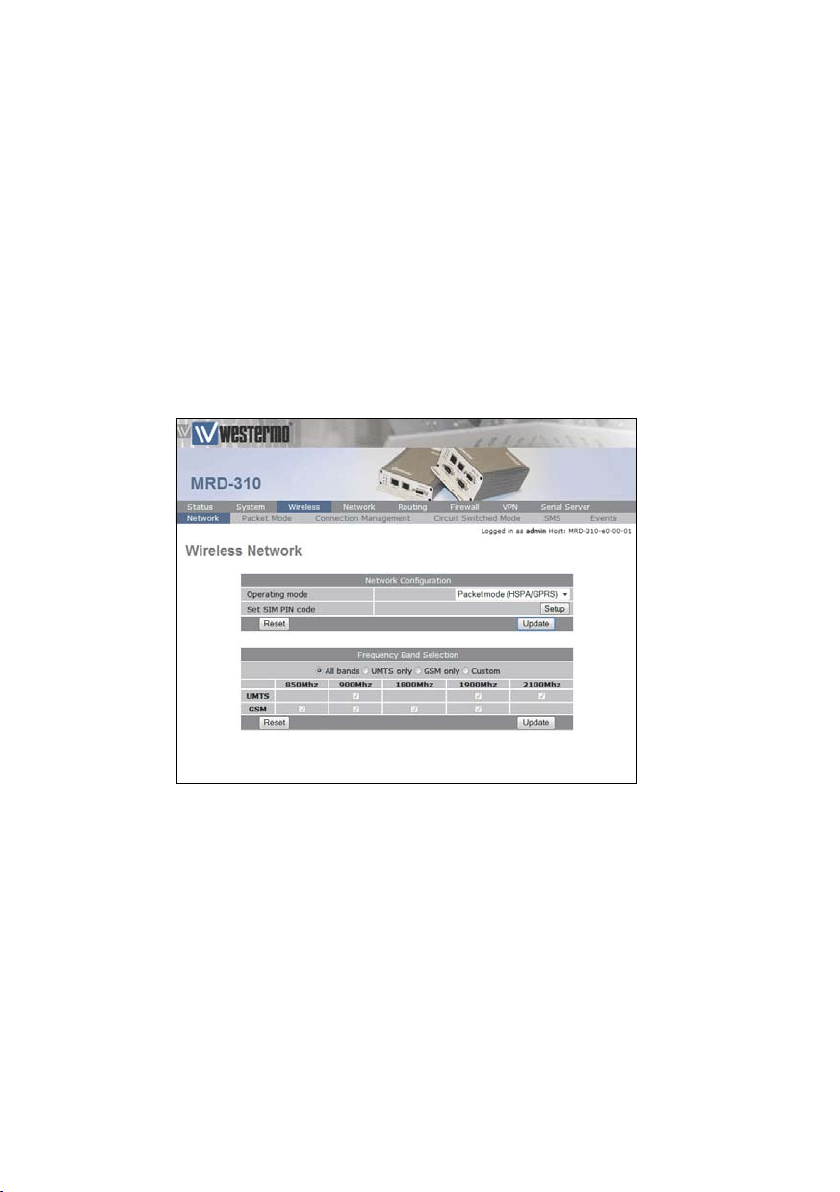
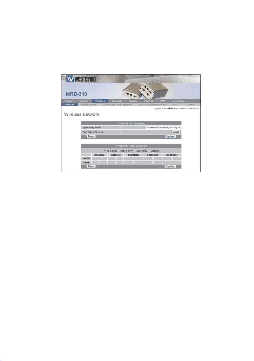
To access the configuration page for the 3G Wireless interface, click on Wireless. The Basic Wireless configuration page
will be displayed as shown in Figure 1.
Figure 1: Wireless Interface Basic configuration.
Page 5

56623-3201
1.1.1 Network Configuration
The Network Configuration section contains the settings for
the operational mode and the frequency band of the unit, the
default settings will usually be adequate to connect the unit to
a packet based network.
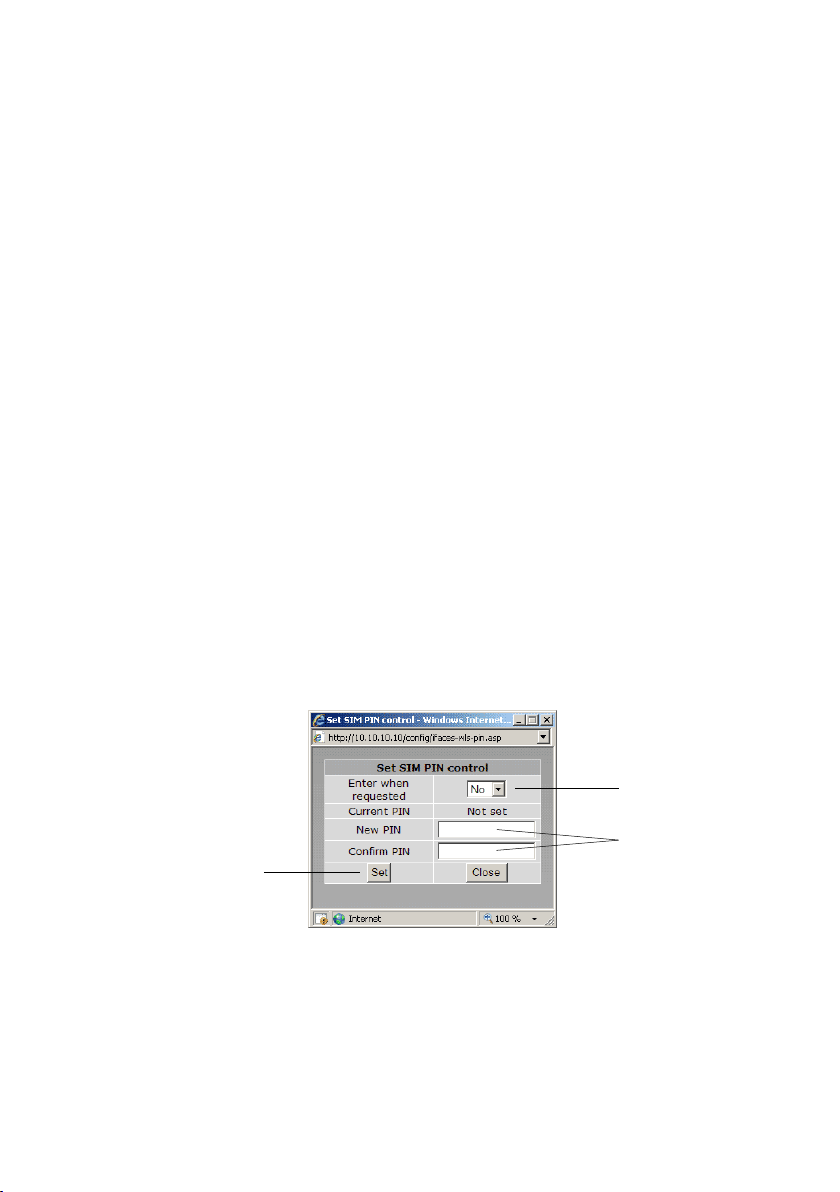
1.1.2 Setting the SIM card PIN
The SIM card may have a PIN associated with it and may
require the PIN to be entered before the unit can access the
SIM. To set the SIM PIN click Setup. A dialog box as shown in
Figure 2 will be displayed.
Figure 2: SIM PIN control dialog.
Set the field marked Enter when requested to Yes and enter the
PIN in the New PIN and Confirm PIN entry boxes. Then click
the Set button to save the PIN.
Click "Set"
to complete
Figure 3: SIM PIN control dialog.
Set to "Yes"
Enter PIN in both
text boxes
Page 6

6 6623-3201
1.1.3 Adding a Network Connection Profile
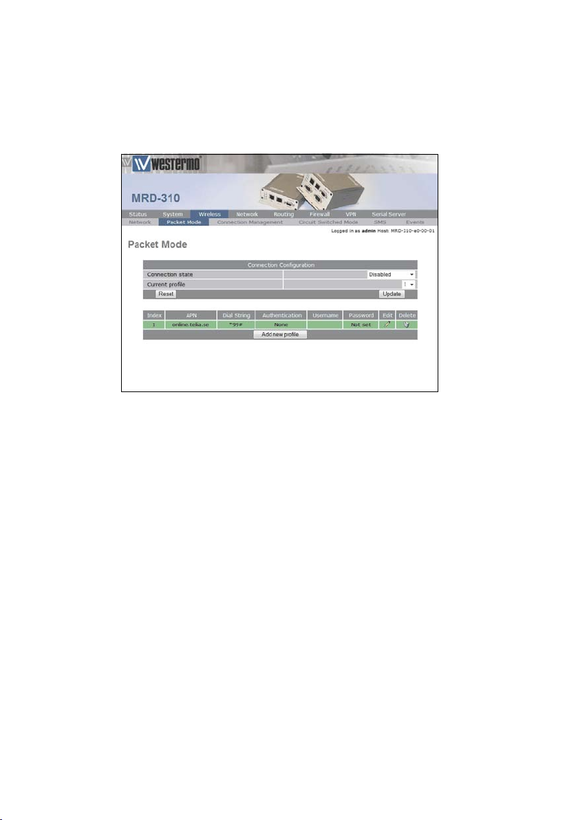
To access the wireless packet mode settings click on the
Packet mode tab. The screen shown in Figure 4 will be displayed.
The page shows the connection configuration details and is
divided into two sections. The first section shows the current
connection state and the selected profile and the second section lists the available profiles. A connection profile groups
together the settings required to connect to a provider's
network. The unit allows multiple profiles to be configured to
allow quick changes to the network connection settings. For
most applications only one profile is required.
Figure 4: Wireless Interface Packet mode settings
Page 7

76623-3201
The 3G network provider will provide the items listed below
which should be entered into the appropriate fields in the Add
new profile section as shown in Figure 5.
APN (Access Point Name)•
Dial string•
Authentication (None / PAP / CHAP)•
Username•
Password•
Note: In order to set a password click the check-box marked
New. The password can now be entered in the text field.
The password is visible as it is being typed so that it can be
checked for errors prior to being set. Once set the password
will no longer be visible.
Note: The provider may not supply a username and password
if network authentication is not required. In this case set the
Authentication to None, leave the username blank and do not
set a password.
Enter APN
Enter dial string
Set Authentication
Enter username
Enter password
Click "Update"
to save profile
Figure 5: Adding a new profile.
Page 8
8 6623-3201
Once the data has been entered click the Update button
to add the profile. The screen will now change to show the
added profile as shown in Figure 6. As this is the only profile
entered it will be automatically selected as the current profile
and the profile entry will be shaded green to indicate that it is
the selected profile.
Figure 6: Profile added and selected.
Page 9

96623-3201
1.1.4 Enable the Wireless Connection
To complete the configuration of the wireless connection, set
the Connection state to Always connect and click the Update
button to save the changes. Once the changes have been set,
the MRD-3xx will initiate a 3G connection. Connection will
normally take up to 30 seconds. Figure 7 shows the completed
wireless configuration.
Figure 7: Completed wireless configuration.
Page 10
10 6623-3201
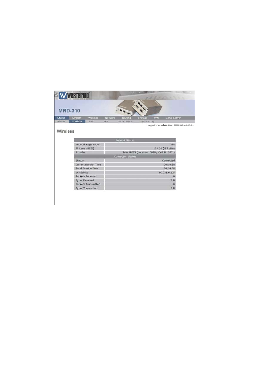
1.1.5 Checking the Status of the Connection
To check the status of the connection select Status from the
top level menu and then select Wireless from the second level
menu. The Wireless status page will be displayed which will
look similar to that shown in Figure 8. The status of the connection will change as the unit connects to the network, first
it will report Checking then Connecting and finally Connected. To
see the value changing the page will need to reload.
Figure 8: Wireless Status page.
Note: If the status is reported as Error then check that the
profile settings have been entered correctly as shown in
Section 3.2.1
Once connected the Status Alarms page should have no faults
listed as shown in Figure 9
Page 11

116623-3201
Figure 9: Status alarm page.
Page 12
12 6623-3201
1.2 Configure the LAN interface and DHCP Server
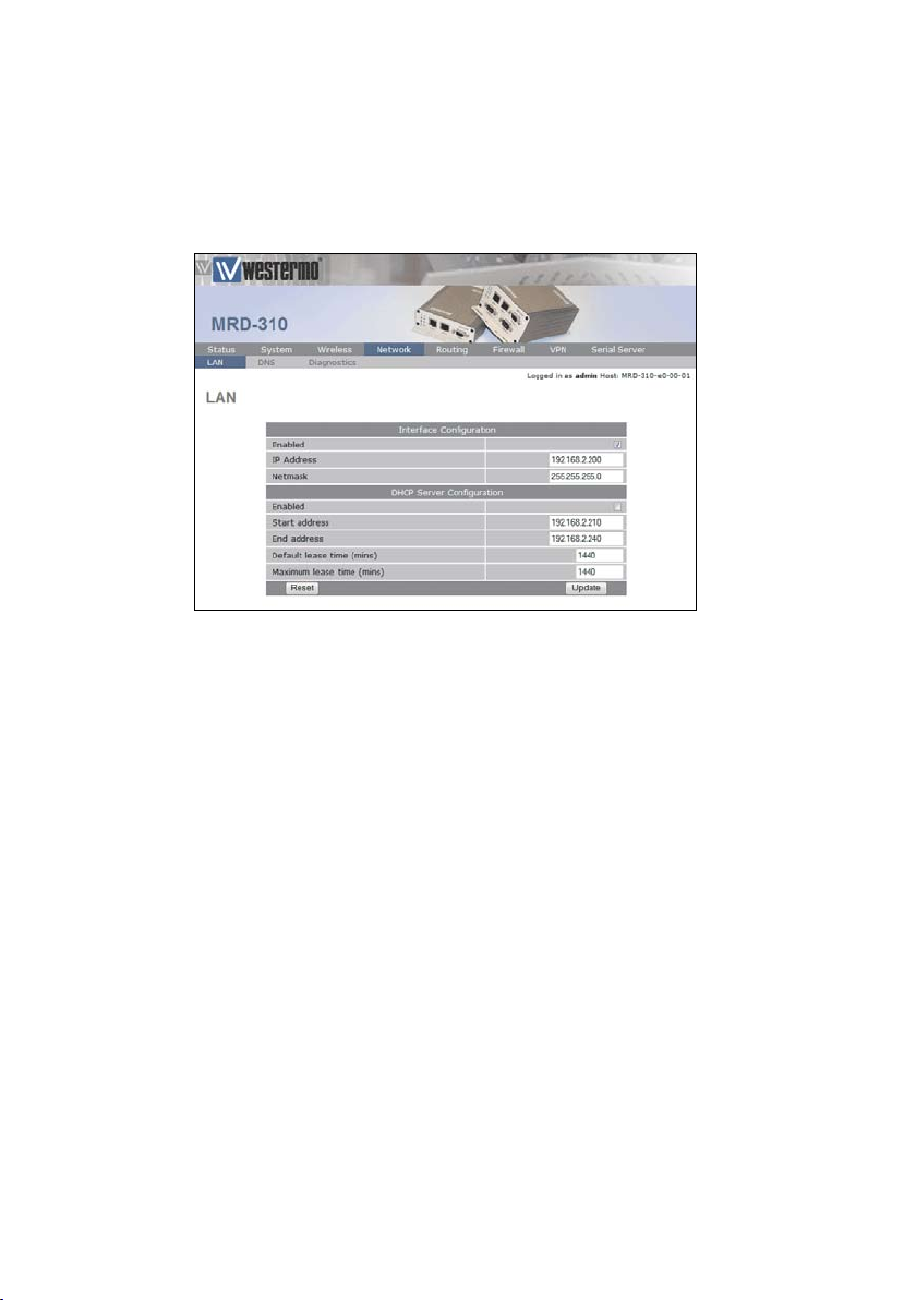
To access the configuration page for the LAN interface and
DHCP Server, select Network from the top level menu and
LAN from the sub menu. The LAN interface screen similar to
Figure 10 will be shown.
Figure 10: LAN interface configuration.
1.2.1 Setting the IP Address
If it is desired to change the IP address of the LAN port, follow the steps below:
Enter the new IP address and netmask in the •
Interface Configuration table.
Click • Update to set the changes. Once the changes
have been set, the IP address of the MRD-3xx Unit
will change. Enter the new address in the browser
on the PC. It will be necessary to login again, following the procedure described in the previous section.
1.2.2 Enabling DHCP
The DHCP server allows clients on the local network to
be automatically allocated IP addresses from the MRD-310.
The unit will also provide the clients with network settings
like their default route and DNS servers. By default the
DHCP server is disabled but if enabled it will be configured
Page 13

136623-3201
to serve IP addresses in the range 192.168.2.210 through
192.168.2.240, and the Default and Maximum lease times have
been set to 1440 minutes. So if these values are consistent
with the network that the MRD-310 is connected to, then the
DHCP can be enabled by setting the Enabled field to Yes and
clicking the Update button.
If the standard settings are not applicable for the connected
network, then refer to Figure 11 and follow the steps below,
to configure the DHCP server:
Figure 11: DHCP configuration.
Set to "Yes" to
enable DHCP server
Set the DHCP
IP address range
Set the DHCP
lease times
Click "Update"
to save changes
Choose a group of available IP addresses on the •
local network. For example, if the IP address
of the MRD-3xx is 192.168.2.200 with a netmask of 255.255.255.0, a group chosen could be
192.168.2.210 to 192.168.2.240. This will provide 31
addresses for clients.
Under the DHCP Server Configuration table, •
Set the o Enabled option to Yes.
Enter the first address of the group in the o
Start Address box.
Enter the last address of the group in the o
End Address box.
Enter a lease time for the o Default Lease
time.
Enter a lease time for the o Maximum Lease
time.
Click • Update to set the changes.
Page 14

14 6623-3201
1.3 Configure clients to use the MRD-3xx
The MRD-3xx will act as a gateway for connections destined
over the wireless interface. The default configuration will provide Network Address Translation and firewalling to protect
clients on the local network.
To configure clients to use the MRD-3xx as their gateway:
If the clients have a DHCP address allocated by the •
MRD-3xx, they will have learned the necessary settings. No further configuration is needed.
If clients have static IP addresses, set their default •
route and DNS server to the IP address of the
MRD-3xx.
Page 15
156623-3201
2 System Administration
The System Administration functions are accessed by selecting
the System tab of the main menu.
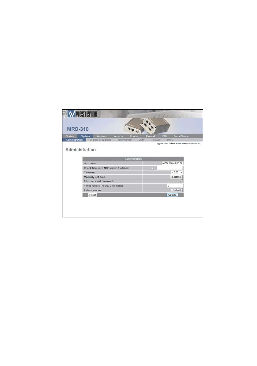
2.1 Administration
To access the Administration features, select •
Administration from the System sub-menu, a page
similar to that shown in Figure 12 will be displayed.
Figure 12: System Administration page.
Page 16

16 6623-3201
The options available are:
Hostname •
Set the required hostname for the MRD-3xx.•
Check time with NTP Server •
Set to Yes to synchronise the internal clock with a NTP
server.
Timezone •
Specify the timezone for location of the MRD-3xx.
Manually set time •
Click button to set time manually.
Edit users and passwords •
Click button to edit users and passwords.
Timed reboot •
Specify a time in hours after which the MRD-3xx will
automatically reboot. Set to 0 to disable automatic reboot.
Reboot unit •
Click the Reboot button to immediately reboot the MRD3xx.
Page 17

176623-3201
2.2 System Information
The MRD-3xx System Information is accessed by selecting the
System Information tab from the System sub-menu. An example
of the System Information page is shown in Figure 13. The first
section of the page lists the Model and serial number of the
unit, plus the firmware and boot-loader version. The seconds
part of the page lists the LAN MAC address the IMEI of the
wireless module, wireless IMSI ant the wireless software version.
Figure 13: System Information page.
Page 18

18 6623-3201
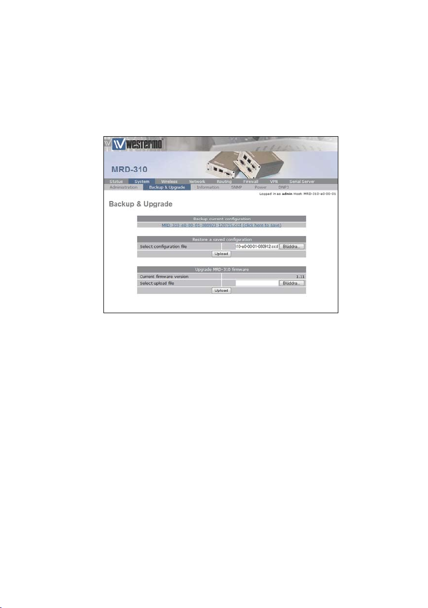
2.3 Configuration Backup & Restore
The configuration of the MRD-3xx can be saved as a file to a
PC. This file can then be used to restore the configuration of
the unit at some later time or used to configure multiple units
with the same configuration. To access the configuration backup restore options select Backup & Upgrade from the System
sub-menu. The Backup & Upgrade page will be displayed as
shown in Figure 14.
Figure 14: Backup and Upgrade page.
To save the current configuration click on the link in the section titled Backup current configuration. A pop-up box similar to
that shown in Figure 15 will be displayed, select Save to Disk
and click OK and select a suitable location to save the file.
Figure 15: Save configuration.
Page 19
196623-3201
To restore a configuration, click the Browse button in the section titled Restore a saved configuration select the configuration
file, which should then be shown in the text box, as shown in
Figure 16, click the Upload button to transfer the file to the
MRD-3xx. Once the upload is complete, the MRD-3xx will
need to be rebooted so the restored configuration can take
affect. The details for performing a reboot can be found in the
Administration section.
Figure 16: Restore configuration.
Page 20
20 6623-3201
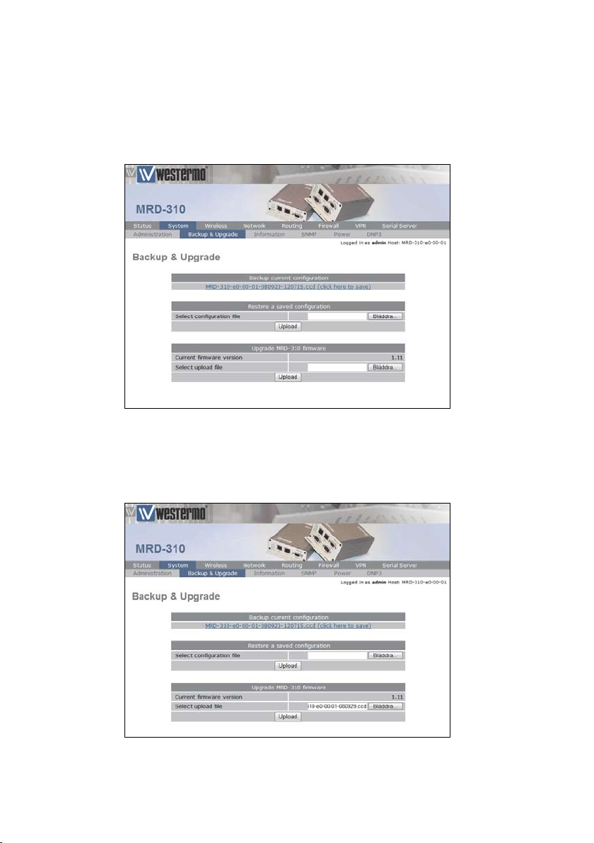
2.4 Firmware Upgrade
The MRD-3xx firmware can be upgraded via the web interface. To access the firmware upgrade page select Backup &
Upgrade from the System sub-menu, the Backup & Upgrade
page will be displayed as shown in Figure 17.
Figure 17: Backup and Upgrade page.
To upgrade the MRD-3xx firmware click the Browse button in
the section titled Upgrade MRD-3xx firmware then select the
navigate to and select the upgrade file.
Figure 18: Select firmware upgrade file.
Page 21

216623-3201
To upload the file to the MRD-3xx click the Upload button.
The file will now be uploaded to the MRD-3xx and, when it
is complete, information on the upgrade file will be displayed,
as shown in Figure 19. At this point the you can chose to cancel the upgrade by clicking the Cancel Upgrade button.
Figure 19: Upload the upgrade file.
To proceed with the upgrade click the Upgrade button, the
page will change to that shown in Figure 20. The firmware
upgrade will now proceed.
Figure 20: Upload the upgrade file.
Note: The upgrade will take several minutes to complete
after which the MRD-3xx will reboot, during this time the
power to the MRD-3xx must not be removed.
Page 22
22 6623-3201
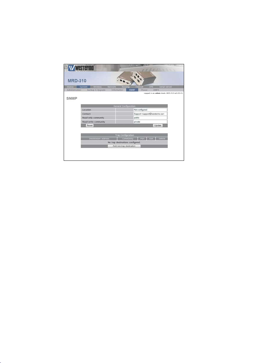
2.5 SNMP
The MRD-3xx supports SNMP for network management of
the unit. The SNMP configuration page can be accessed by
selecting the SNMP tab of the System sub-menu.
Figure 21: The SNMP configuration page.
Page 23

236623-3201
2.6 GPIO (MRD-330 only)
The MRD-330 has two general purpose digital inputs and two
general purpose digital outputs, the options for these can be
found by selecting GPIO on the System sub-menu.
Figure 22: The General Prupose I/O configutration page.
Page 24

24 6623-3201
3 Wireless Interface Configuration
This section describes the 3G Wireless interface options of
the MRD-3xx. The MRD-3xx supports two modes of operation: packet mode and Circuit Switched Data (CSD) mode.
The Wireless menu contains the settings for the Wireless
Interface. To display the settings, click on the Wireless tab on
the top menu bar.
The subsections of the configuration are:
Network
Configure the operation mode, select the frequency band of
operation and set the SIM PIN.
Packet mode
Configure the packet mode.
Connection Management
Advanced configuration of the network connection.
Circuit switched mode
Configure the circuit switched data mode.
SMS
Configure the Short Message Service (SMS) functionality of
the unit.
Events
Configure the event reporting of the unit.
Page 25
256623-3201
3.1 Network Configuration
The Wireless Network options are used to set the operating mode, select the frequency band of operation and set the
SIM PIN. To display the Network page select Wireless from the
main menu, the Network page is the default page displayed, it
should appear similar to that of Figure 23.
Figure 23: Wireless Network configuration.
Page 26

26 6623-3201
3.1.1 Wireless Operating Mode
The MRD-3xx support two modes of operation, packet mode
and Circuit Switched Data (CSD) mode. In packet mode the
MRD-3xx acts as a TCP/IP unit and router, data can be routed
between the LAN ports and the Wireless port and the serial
server is used to interface the serial ports to the packet interface of the network. Circuit Switched Data mode is similar
to tradition dial-up unit, in this mode one serial port of the
MRD-3xx is connected to the Wireless interface, once connected all data coming into the Wireless port is directed to
the serial port and all data received by the serial port is transmitted to the Wireless interface.
To set the mode of the MRD-3xx select Wireless from the
main menu and Network from the Sub-menu then select either
Packet mode (HSDPA/GPRS) or Circuit switched mode from
the drop-down menu adjacent to Operating mode, once the
mode has been selected click the Update button the commit
the change. Figure 24 displays the MRD-3xx operating mode
options.
Figure 24: Wireless Network operating mode options.
Page 27
276623-3201
3.1.2 Operating Frequency Band
The MRD-3xx is capable of operating on several frequencies
and using the GSM or UMTS (3G) protocols. By default the
MRD-3xx is set to operate on all bands, this means that when
powered on the MRD-3xx will start to search for available
networks, when a network is found it will check if the SIM
is valid for that network and if so attempt to connect to it.
If it cannot connect to the network it will then move to the
next network and try again. The search will start using UMTS
(3G) if the network list is exhausted without finding a valid
network the MRD-3xx will then attempt to connect using
GSM. Using the options available for the frequency band it is
possible to restrict the band and protocol search to a limited
number, this may mean a quicker connection time and it also
means that the MRD-3xx will not connect in an unexpected
mode. Frequency band selection shows the available frequency
band options.
3.1.3 Setting the SIM card PIN
The SIM card will have a PIN associated with it, if PIN checking is enabled on the SIM then in order for the unit to access
the SIM, the PIN will need to be set in the unit. To set the
SIM PIN click Setup a dialog box as shown in Figure 26 will be
displayed.
Click "Set"
to complete
Set to "Yes"
Enter PIN in both
text boxes
Figure 26: SIM PIN control dialog.
Page 28

28 6623-3201
Set the field marked Enter when requested to Yes and enter the
PIN in the New PIN and Confirm PIN entry boxes.
Then click the Set button to save the PIN.
Figure 27: SIM PIN control dialog.
Page 29

296623-3201
3.2 Packet Mode Configuration
The packet mode options are described in this section.
3.2.1 Adding a Network Connection Profile
To access the wireless packet mode settings select Wireless
from the main menu then select the Packet mode tab from the
sub-menu, the screen shown in Figure 28 will be displayed. The
page shows the connection configuration details and is divided
into two sections. The first section shows the current connection state and the selected profile. The second section lists the
available profiles. To add a new profile, click Add a new profile
and a screen similar to Figure 29 will be displayed. A connection profile groups together the settings required to connect
to a provider's network, the MRD-3xx allows multiple profiles to be configured to allow quick changes to the network
connection settings. For most applications only one profile is
required.
Figure 28: Wireless Interface Packet mode settings.
Page 30

30 6623-3201
The 3G network provider will provide the items listed below
which should be entered into the appropriate fields in the Add
new profile section as shown in Figure 29.
APN (Access Point Name)•
Dial string•
Authentication (None / PAP / CHAP)•
Username•
Password•
Figure 29: Adding a new profile.
Enter APN
Enter dial string
Set Authentication
Enter username
Enter password
Click "Update"
to save profile
Note: In order to set a password click the check-box marked
New, the password can now be entered in the text field. The
password is visible as it is being typed so that it can be
checked for errors prior to being set, once set the password
will no longer be visible.
Note: The provider may not supply a username and password
if network authentication is not required, in this case set the
Authentication to None, leave the username blank and do not
set a password.
Once the data has been entered click the Update button
to add the profile. The screen will now change to show the
added profile as shown in Figure 30, as this is the only profile
entered it will be automatically selected as the current profile
and the profile entry will be shaded green to indicate that it is
the selected profile.
Page 31

316623-3201
Figure 30: Profile added and selected.
Additional profiles can be added using the same procedure, to
a maximum of five profiles. This is illustrated in Figure 31, the
configuration shown has 4 profiles, profile 1 is the selected
profile, this is highlighted by the green background of
this profile in the profile index.
Figure 31: Multiple profiles added.
Page 32

32 6623-3201
3.2.2 Deleting a Profile
A profile can be deleted by clicking the Bin icon located in the
Delete column, for the profile to be deleted. For example to
delete profile 4 from the profile list shown in Figure 31, click
on the Delete icon, a warning dialog box will appear, similar to
that shown in Figure 32 click OK to delete the profile.
Figure 32: Profile delete warning.
The page will be re-displayed as shown in Figure 33 with profile 4 removed from the profiles index.
Figure 33: Profile 4 deleted.
Page 33

336623-3201
3.2.3 Editing a Profile
To edit an existing profile click on the Edit icon for the profile
you wish to edit. For example to edit profile 1 in the
profile list shown in Figure 33 click the Edit icon for profile
1, the information for that profile will now appear in a new
screen as shown in Figure 34. Complete the changes to the
profile, then click the Update button to commit the changes.
Figure 34: Editing a profile.
Page 34

34 6623-3201
3.2.4 Enable the Wireless Connection
To complete the configuration of the wireless connection,
the connection needs to be enabled. There are two connection options available, Always connect and Disabled, select the
desired option, select the desired profile and click the Update
button to save the changes. Once the changes have been set,
the MRD-3xx will initiate a 3G connection, connection may
take up to 120 seconds. Figure 35 shows an example of a
Wireless packet mode configuration.
Figure 35: Completed wireless configuration.
Page 35

356623-3201
3.2.5 Checking the Status of the Connection
To check the status of the connection select the Status tab
from the main menu and then select the Wireless tab from the
sub-menu. The Wireless status page will be displayed which
will look similar to that shown in Figure 36. The status of
the connection will change as the unit connects to the network, first it will report Checking then Connecting and finally
Connected, to see the value changing the page will need to be
refreshed.
Figure 36: Wireless status page.
Indicates modem is
registerd to a network
Received Signal Level
(RSSI)
Network provider
details plus cell
locations and ID
Indicates modem is
connected to a network
Session timers
Wireless interface IP
address
Packet and byte counter
Page 36

36 6623-3201
The section titeld Network Status details the quality of the
service available from the 3G network.
The SIM Card field will only be shown if an error with •
the SIM card has been detected, and will be reported as
Absent or faulty as shown in Figure 38.
If the SIM card fault is reported, possible causes include:•
The SIM card has not be inserted correctly, refer o
to the User Guide, for details on how to insert the
SIM card.
The SIM card pin number has not been entered or o
is incorrect, refer to section 3.1.3, for details on
entering the SIM card PIN.
The • Network Registration field indicates whether the
MRD-3xx is actively registered to the 3G network.
No connection is possible without registration. If the
Network Registration field is No, possible causes include:
Poor signal strength. Check that the antenna is o
properly connected and experiment with different
locations for the MRD-3xx to achieve a higher RF
Level.
Problem with the SIM card. Ensure that the SIM o
card fitted to the MRD-3xx is currently enabled
with the network provider.
The • RF Level indicates the current strength of received
signal from the network, with a maximum of 30. Any level
over 10 should provide acceptable connection speeds.
The Connection Status table shows the statistics for the current connection.
Page 37

376623-3201
Figure 38: Wireless Status page showing a SIM fault.
If the Status item doesn't show • Connected, verify the fol-
lowing:
Operation is • Enabled under the Wireless configuration.
If the Status field always shows • Connecting..., a problem
with the APN, username or password is likely. Check
that the values these settings with the network provider.
Refer to Section 3.2.1 for details on how to enter these
values into the MRD-3xx.
The remaining fields list the length of time connected, IP
address allocated by the network and data counters. All of this
information will reset if a connection is restarted, except the
Total Session Time field, which will accumulate across all sessions.
Page 38

38 6623-3201
Once all errors have been resolved and the MRD-3xx is connected to a wireless network, the Status Alarms page should
have no faults listed as shown in Figure 39.
Figure 39: Status Alarm page.
Page 39

396623-3201
3.3 Connection Management
The MRD-3xx has numerous options for managing the wireless network connection, these option cover two main areas,
connection establishment and connection maintenance.
To access the Wireless connection management options
select the Wireless tab from the main menu and then select
the Connection management tab from the sub-menu, the
Connection management page as shown in Figure 40 will be
displayed.
Figure 40: Wireless connection management page.
Page 40

40 6623-3201
3.3.1 Connection Establishment
The connection establishment options are used to set the
parameters for initial connection to a providers wireless network. The options are:
Timeout for network initialisation:
Specify the maximum time in seconds to allow for a network
initialisation, the minimum value accepted is 60 Seconds.
Timeout for connection establishment:
Specify the maximum time in seconds to allow for a connection to be established, the minimum value accepted is 30
Seconds.
Remote poll required for successful connection:
Specify if a remote poll should be completed before considering the connection successful. If this option is set to Yes then
the Remote Poll Setup must be enabled and configured correctly, refer to section 3.3.3
Timeout between remote poll attempts:
Specify the time in seconds to wait between successive
polls should a poll fail. This option is only available when the
Remote poll required for successful connection option is set
to Yes.
Failed establishment attempts before RF restart:
Specify the number of failed connection attempts before
restarting the RF circuitry. Set this value to 0 to disable RF
Circuitry reset.
Failed establishment attempts before unit reboot:
Specify the number of failed connection attempts before
resetting the MRD-3xx. Set this value to 0 to disable the
MRD-3xx reset.
Failed establishment attempts before dropping to CSD:
Specify the number of failed connection attempts before
switching to Circuit Switched Data (CSD) mode. Set this value
to 0 to disable the fail-over to CSD feature.
Page 41

416623-3201
Time to spend in CSD:
Specify a time in minutes to remain in CSD mode before
reverting to packet mode and attempting to establish a connection. This value value is only used if the Failed establishment attempts before dropping to CSD option is set to a
value greater than 0.
Page 42

42 6623-3201
3.3.2 Connection Maintenance
The connection maintenance refers to the tests employed by
the MRD-3xx to determine that a valid network connection is
available. Should the connection maintenance test fail then
the MRD-3xx will attempt to re-establish the connection. The
remote poll and server configuration is described in section
3.3.3.
The connection maintenance options are:
Remote polling mode
Specify the connection maintenance operating mode, the 4
options are:
1. Disable: Connection maintenance is disabled.
2. Poll at fixed interval: Poll the specified server at the interval
specified.
3. Poll if Rx idle for interval: Only poll the specified server
when not data has been received from the wireless interface
for the specified interval.
4. Reconnect if Rx idle for interval: Reconnect if data has not
been received by the wireless interface for the specified interval.
Interval between successful polls:
Specify the time interval in minutes between polls.
Timeout between failed polls:
Specify the time in seconds between failed polls.
Failed polls before returning to establishment:
Specify the number of failed polls to declare the link failed and
to re-start the establishment process.
Traffic generator enabled, interval (secs) and addresses:
Specify the address of the remote server that the on-board
traffic generator should send traffic to.
Page 43

436623-3201
3.3.3 Remote Poll Setup
The remote poll setup is used to specify the poll type to use
and the address of the server to poll. A primary and secondary server may be specified, the secondary server will be used
if the primary server cannot be contacted. The options are:
Primary poll type
Specify the poll type, the options are:
1. Disabled: Primary poll is disabled.
2. Ping (ICMP): Ping the specified address.
3. TCP Socket: Establish a TCP socket to the specified address,
the connection will be established then after a few seconds
terminated.
Primary poll address
Specify the address of the primary server to poll.
Backup poll type
1. Disabled: Primary poll is disabled.
2. Ping (ICMP): Ping the specified address.
3. TCP Socket: Establish a TCP socket to the specified address,
the connection will be established then after a few seconds
terminated.
Backup poll address
Specify the address of the secondary server to poll.
Page 44

44 6623-3201
3.3.4 Miscellaneous Options
Automatically obtain DNS:
If set to Yes the DNS server address passed when a connec-
tion is established will be used by the MRD-3xx to direct
DNS requests. If this value is set to No a DNS server should
be entered manually.
Verbose output to system log:
If set to Yes verbose connection information will be included
in the system log. As the size of the system log is limited, this
option should only be enabled if connection problems are
being experienced.
Page 45

456623-3201
3.3.5 Connect on Demand
The connect on demand settings are only valid if the Wireless
connection state has been set to always connect, refer to section 3.2.4.
The options are:
Idle time to disconnect:
Specify the time in minutes after the last data receive or
transmit to terminate the connection.
Minimum time between reconnections:
Specify the minimum time in seconds to re-connect to the
network after a disconnect from the network.
3.4 Circuit Switched Data (CSD) Mode
MRD-3xx can be configured to work in Circuit switched
Data (CSD) mode. This mode works in a similar manner to a
traditional dial-up unit. The MRD-3xx can be "dialed" by calling its associated data number, the MRD-3xx will answer the
call and make a direct connection from the wireless port to a
serial port. Once connected all data coming into the wireless
port will be directed to the serial port and all data received
by the serial port will be directed to the wireless port. When
in CSD mode the MRD-3xx can only connect one serial port
to the wireless port. The LAN interface will still be active and
the MRD-3xx will still be accessible however no packet will
be able to be routed to the wireless port. The MRD-3xx can
operate in CSD "Single port" meaning only one serial port can
be accessed, or CSD "Multiplexed" meaning one of the serial
ports can be selected on connection.
Note: This section does not describe the serial port configuration, for details on configuring the serial ports refer to section 7 Serial Server.
Page 46

46 6623-3201
3.4.1 CSD Single Port
The simplest configuration for Circuit Switched Data (CSD) is
single port operation, this means that when a connection is
established the pre-configured serial port is always connected.
The Circuit switched mode settings are access by selecting the Wireless tab from the main menu and then Circuit
switched mode from the sub-menu, Figure 41 shows the Circuit
switched mode page. The selected port will always be provided with a standard "AT" command interface, allowing a device
attached to the port to initiate dialing and answer incoming
calls.
Figure 41: Circut Switched Data (CSD) mode page.
1. Set the Operating mode to Direct to single port and click
Update.
2. Click on the Edit icon of desired serial port to access unit
configuration. A new screen will be displayed.
3. Set the number of rings until answered, the DCD Mode and
the DTR function for the port selected in step 2.
4. Click Update to save the changes.
Page 47

476623-3201
3.4.2 CSD Multiplexed
The Circuit Switched Data (CSD) Multiplexed mode allows any
one of the available MRD-3xx serial ports to be selected at
the time of connection. This is achieved through having a virtual console to which the initial connection is made. The caller
can then issue a command to select a port. Once selected, all
data will be directed to the port.
Multiplexed mode can be configured to have a default port.
This port will be selected should no connection command
have been received within a specified time period or a number
of bytes have been received.
A disconnection sequence can be described which when
received by the MRD-3xx will disconnect the serial port currently selected and return the connection to the virtual terminal. Another port can then be selected, allowing communication with multiple devices in one CSD telephone call.
The virtual terminal can operate in a verbose mode which
will send prompts and echo characters sent to it. This mode is
best used when issuing the commands manually as it provides
the user with feedback. Alternatively the virtual terminal can
operate in silent mode returning no character to the connection. This mode is best used when doing a machine-to-machine
type connection, where spurious character could cause problems.
The command used to select the required port is:
PORT=x\r
where x is the number of port and \r is a carriage return
(0x0d ASCII). No spaces should be present within the command string and the command.
The disconnect string is of the form:
<guard time><disconnect character><disconnect
character><disconnect character><guard time>
Page 48

48 6623-3201
For example if the guard time is set to 2 seconds and the disconnect character is 3F (? ASCII) then the disconnect sequence
would be:
<2 seconds>???<2 seconds>
Upon receiving this sequence the MRD-3xx would disconnect
from the currently connected serial port and return control
to the virtual terminal.
Figure 42: Circuit Switched Data (CSD) mode port multiplexed page.
Page 49

496623-3201
To configure CSD Multiplexed mode complete the following steps:
1. Select the Wireless tab from the main menu and then select
Circuit switched mode tab from the sub-menu.
2. Set the Operating mode to Multiplexed and click Update.
Click the Edit icon for desired port.
3. In the section titled Multiplexed Mode Configuration:
Set the Menu visibility to either • Silent or Verbose.
Set the • Disconnect character in hex, leave it blank for
no disconnect character. This value is specified in
hex so that it is not limited to text values.
Set the • Disconnect guard time in seconds.
Set the • Default port to use should a port select command not be received.
Set the number • Bytes to wait from connection until the
default port selected.
Set the number of • Seconds to wait from connection
until default port selected.
4. The second configuration section allows the parameters
for each port to be set up. Each port can act in one of two
modes:
(a) Raw mode: The port will be inactive except when
selected during a CSD call. Data will pass transparently
through the multiplexer. This is suited to communicating
with devices that do not expect to see an AT command
interface.
(b) Unit mode: The port provides an AT command
interface. A device attached to the port will see a simulated AT command interface that will indicate when a call
is incoming and allow the port to initiate dialing of a CSD
call. The is suited to devices that expect to see a dial-up
type interface.
5. Click the Update button to save the changes.
Page 50

50 6623-3201
3.5 SMS Triggers
The MRD-3xx provides SMS triggers which can be used to
change the Wireless operating mode, reboot the unit and
request a status summary. Each SMS trigger can individually be
enabled and disabled and the text trigger can be defined for
each trigger.
Access control is provided to control what numbers have
access to the SMS triggers.
3.5.1 Trigger configuration
To access the SMS Triggers select the Wireless tab from the
main menu and the SMS tab from the sub-menu. A page similar to that of Figure 43 will be displayed. To configure the triggers complete the following steps:
1. For each of the triggers to be enabled, tick the Enabled
checkboxes.
2. For each of the triggers to be disabled, untick the Enabled
checkboxes.
3. For each of the triggers that has been enabled set the
Match on field to:
(a) Exact: The received text must exactly match the
Trigger string, any additional characters will cause a mismatch.
(b) Contains: The received text must contain the
Trigger string, additional characters can be received.
(c) Start with: The received text must start with the
Trigger string, no additional characters can be received
before the Trigger string.
4. For each of the enabled triggers set the Trigger string to the
desired text.
5. Click the Update button to save the changes.
Page 51

516623-3201
Figure 43: SMS Triggers configuration page.
Page 52

52 6623-3201
3.5.2 Access Control
The SMS Access Control allows fine control over the access
to the SMS triggers. The default policy can be set to allow
which will allow any number that has not be specifically set to
be denied, or the default policy can be set to deny in which
case all numbers will be denied unless specifically set to allow.
Page 53

536623-3201
3.5.2.1 Example: Default policy accept
To set the SMS Access Control for a default action of allow
and to specifically block a number, refer to Figure 43.
and complete the following steps:
1. Click the Add new access control button.
2. In the section titled Add new SMS access control:
(a) Add a label for the new entry.
(b) Enter the phone number.
(c) Set the Action to Drop.
3. Click the Update button to save the changes.
4. Repeat the steps above to add further numbers.
When complete the page will include the number to be
dropped, as shown in Figure 44.
44.
Figure 44: SMS Triggers number to drop added.
Page 54

54 6623-3201
3.5.2.2 Example: Default policy to Drop
To set the SMS Access Control for a default action of drop
and to specifically accept a number, refer to Figure 45 and
complete the following steps:
1. In the section titled SMS Access Control set the Default
policy Action to Drop.
2. In the section titled Add new SMS access control:
(a) Add a label for the new entry.
(b) Enter the phone number.
(c) Set the Action to Accept.
3. Click the Update button to save the changes.
4. Repeat the steps above to add further numbers.
When complete the page will include the number to be
accepted, as shown in Figure 46.
Figure 45: SMS Triggers accept entry.
Page 55

556623-3201
Figure 46: SMS Triggers number to accept added
Page 56

56 6623-3201
4 Network
This section describes the confiuration of the Network or
LAN settings. This includes setting the IP Address of the MRD3xx Unit, configuring the DHCP server and the DNS settings.
4.1 LAN Interface
The LAN Interface refers to the two switched Ethernet ports
located on the front of the MRD-3xx. To access the LAN
Interface settings select the Network tab from the main menu
then the LAN tab from the sub-menu.
4.1.1 Changing the IP Settings of the LAN
Interface
The LAN IP address is the address used to access the MRD3xx via the LAN (Ethernet) interface. The default IP settings of
the MRD-3xx Unit / Router are:
IP Address: 192.168.2.200•
Netmask: 255.255.255.0•
The Network settings are contained on the Network / LAN
page under the Interface Configuration heading. To change the IP
settings :
1. Click the Network tab on the main menu, this will display the
LAN page as shown in Figure 47, the LAN interface settings are
in the section titled Interface Configuration.
2. Ensure that Enabled is set to Yes.
3. Enter the IP address in the IP Address box.
4. Enter the Netmask in the Netmask box, to that of the subnet to which the unit is connected.
5. Click the Update button at the bottom of the page to commit the changes.
Page 57

576623-3201
Figure 47: LAN Interface configuration.
Note: Once the IP Address has been changed the new IP
address will need to entered into the web browser to re-gain
access the MRD-3xx web interface, it will also be necessary to
login again. For details on accessing the web pages and logging
into the MRD-3xx refer to the User Guide.
Page 58

58 6623-3201
4.1.2 Disabling the LAN Interface
By default the LAN interface is enabled. The LAN interface
can be disabled if the LAN ports are not required.
Note: If the LAN ports are disabled then access to the web
configuration pages will only be available via the wireless interface if the the Firewall settings allow access to the Web Server,
for details on the Firewall configuration refer to Section 5. To
re-enable the LAN ports without accessing the Web interface,
it will be necessary to perform a factory reset of the MRD3xx as described in the User Guide, this will clear all the
configuration settings of the MRD-3xx to the factory default
settings and the LAN ports will be enabled.
To disable the LAN Interface :
1. Click the Network tab on the main menu, this will display the
LAN page as shown in Figure 47 the LAN interface settings are
in the section titled Interface Configuration.
2. Untick Enabled checkbox.
4. Click Ok.
5. Click the Update button at the bottom of the page to commit the changes.
The LAN interface will now be disabled, if the connection to
the MRD-3xx was via the LAN ports, a page error may now
be indicated.
Page 59

596623-3201
4.2 DHCP Server Configuration
The DHCP server allows clients on the local network to be
automatically allocated IP addresses from the MRD-3xx. The
MRD-3xx will also provide the clients with network settings
like their default route and DNS servers.
By default the DHCP server is disabled however it has been
configured to serve IP addresses in the range 192.168.2.210
through 192.168.2.240, and the Default and Maximum lease
times have been set to 1440 minutes. So if these values are
consitant with the network that the MRD-3xx is connected
to, then the DHCP can be enabled by setting the Enabled field
to Yes and clicking the Update button.
Figure 49: DHCP configuration.
If the standard settings are not applicable for the connected
network, then refer to Figure 49 and follow the steps below,
to configure the DHCP server:
1. Click the Network tab on the main menu, this will display the
LAN page as shown in Figure 49, the DHCP settings are in the
section titled DHCP Server Configuration.
Page 60

60 6623-3201
2. Choose a group of available IP addresses on the local
network. For example, if the IP address of the MRD-3xx is
192.168.2.200 with a netmask of 255.255.255.0, a group chosen could be 192.168.2.100 to 192.168.2.199. This will provide
100 addresses for clients.
3. Tick the Enabled checkbox.
4. Enter the first address of the group in the Start Address box.
5. Enter the last address of the group in the End Address box.
6. Enter a lease time for the Default Lease time.
7. Enter a lease time for the Maximum Lease time.
8. Click the Update button to commit the changes.
4.3 Configuring clients to use the MRD-3xx
The MRD-3xx will act as a gateway for connections destined
over the wireless interface. The default configuration will provide Network Address Translation (NAT) and firewalling to
protect clients on the local network.
To configure clients to use the MRD-3xx as a gateway:
If the clients have a DHCP address allocated by the •
MRD-3xx, they will have learned the necessary settings. No further configuration is needed.
If clients have static IP addresses, set the default •
route and DNS server to the IP address of the
MRD-3xx.
Page 61

616623-3201
4.4 Domain Name System (DNS)
The Domain Name System (DNS) is used to resolve domain
names to IP addresses. When connecting to a wireless network the MRD-3xx normally receives the IP address of a DNS
server to use for DNS requests. The MRD-3xx supports DNS
proxy, Manual DNS Configuration and a Dynamic DNS client.
The features can be accessed by selecting Network from the
main menu and then DNS from the sub-menu. The DNS settings page is shown as in Figure 50.
Set to "Yes" to
enable DNS client
Set the DNS service
Enter the DNS domain address
Enter DNS client username
Enter DNS client password
Click "Update" to save changes
Figure 50: Domain Name Service (DNS) configuration.
4.4.1 DNS Proxy
The MRD-3xx is configured by default to act as a Domain
Name Server (DNS) proxy, this means that the MRD-3xx
passes DNS requests from the LAN interface to an external
DNS server, and returns the result to the client which initiated the DNS request.
Therefore all devices connected to the LAN Interface can
specify the IP address of the MRD-3xx as the DNS server. If
the DHCP server of the MRD-3xx has been enabled, then any
device that is connected to the LAN interface and requests an
IP address via DHCP will automatically be given the IP address
of the MRD-3xx as the DNS server.
Page 62

62 6623-3201
4.4.2 Manual DNS Configuration
The manual DNS configuration is used to select a DNS server
other than the one automatically supplied by the wireless network. To configure the manual DNS :
1. Enter an IP address for the primary DNS server in the
Primary DNS Server box.
2. Optionally enter the IP address for a secondary DNS server
in the Secondary DNS Server box.
3. Enter the DNS domain in the DNS Domain box.
4. Click the Update button at the bottom of the page to commit the changes.
The MRD-3xx will now use the DNS Server at the supplied IP
addresses for all DNS requests.
4.4.3 Dynamic DNS Client Configuration
Dynamic DNS is a system which allows the domain name
data held in a name server to be updated in real time. The
most common use for this is in allowing an Internet domain
name to be assigned to a device with a dynamic IP address.
Depending on the system used by the wireless provider the
MRD-3xx may receive a dynamic IP address, using this service
it may be possible to establish connections to the MRD-3xx
without needing to track the IP address of the MRD-3xx. This
makes it possible for other sites on the Internet to establish
connections to the machine without needing to track the IP
address themselves.
Note: Some service providers do not allow access to dynamic IP address, so even though the Dynamic DNS client will
connect and register the IP address provided to the MRD-3xx
unit, all attempts to connect to that IP address will fail.
In order to use the Dynamic DNS feature of the MRD-3xx
you will first need to register at a Dynamic DNS provider, the
MRD-3xx supports the follwoing providers:
Drop-down option Provider
dyndns.com http://www.dyndns.com/
no-ip.com http://www.no-ip.com/
zoneedit.com http://zoneedit.com/
easydns.com http://www.easydns.com/
Page 63

636623-3201
Once registration is complete follow the steps below to
configure the MRD-310/330, for reference Figure 51 show an
example configuration.
1. Click the Network tab on the main menu, then select
DNS from the sub-menu, this will display the DNS page, the
Dynamic DNS settings are in the section titled Dynamic DNS
Client Configuration.
2. Tick Enabled checkbox.
3. Select the service provider from the Service drop-down
menu.
4. Enter the Domain in the Domain text box.
5. Enter the username for your account in the Username text
box.
6. Enter the password for your account in the Passoword text
box.
7. Click the Update button to save the changes.
Figure 51: Dynamic Domain Name Service (DNS) Client configuration.
Page 64

64 6623-3201
5 Firewall
The MRD-3xx has a Stateful Packet Inspection (SPI)
Firewall that controls the connections from the wireless port
to the LAN ports and to the unit itself. The firewall can be
used to limit the connections that can be established to or via
the unit. For example, if the unit is only to be used for serial
communications then the firewall can be set-up to only allow
connections through to the serial server (which connects to
the serial ports).
5.1 Firewall Setup
The MRD-3xx firewall configuration is accessed by selecting
the Firewall tab from the main menu. When selected the page
shown in Figure 52 will be displayed. This page shows
and allows configuration of the basic settings for the firewall.
Figure 52: Basic firewall conguration.
Page 65

656623-3201
5.1.1 Network Address and Port Translation
(NAPT)
As connection pass from the LAN network out the wireless port, the firewall can perform Network Address and Port
Translation (NAPT). When set, this option will cause the firewall to substitute the address of the wireless port for the
source address of connections received from the LAN network. This is most useful where the LAN network is a private
network but the wireless port has a public address.
In some cases, for example, if connected to an IP WAN that
supports direct routing to the LAN network of the unit, it
may be desirable to disable the NAPT function. This will allow
clients on the LAN to be directly addressed without the need
for port forwards. To disable NAPT, uncheck the Connections
from LAN checkbox and press Update.
5.1.2 Stateful Packet Inspection (SPI)
The firewall in the unit can function in Stateful Packet
Inspection (SPI) mode. When enabled, the firewall will track
the state of each connection passing through it (for example,
TCP streams) and only allow packets belonging to a known
connection to enter from the wireless port. In most cases, SPI
should be enabled for greater security. When disabled, the firewall will allow all incoming packets from the wireless port to
be forwarded through to the LAN network.
In some cases, for example, if connected to an IP WAN that
supports direct routing to the LAN network of the unit, it
may be desirable to disable the SPI function. This will allow
clients on the LAN to be directly addressed without the need
for port forwards. To disable SPI, uncheck the Accept only
established destined to LAN checkbox and press Update.
Page 66

66 6623-3201
5.1.3 Connection tracking options
The firewall can be configured to optionally provide connection tracking and NAT support for a number of additional
protocols. The protocols are listed in Table 1.
To enable support for a protocol, click the checkbox for the
protocol and press Update.
Protocol Description
FTP Adds support for active mode File Transfer
Protocol
TFTP Adds support for the Trivial File Transfer
Protocol
H.323 Adds support for the H.323 voice and videocon-
ferencing protocol
PPTP Adds support for the Point-to-point Tunneling
Protocol
IRC Adds support for the Internet Relay Chat pro-
tocol
Table 1Firewall Connection tracking options
Page 67

676623-3201
5.2 Access Control
The Access Control page allows configuration of the firewall
to allow or deny access to internal services of the unit from
the wireless port and VPN tunnels. By default, the firewall
will block access from the wireless port to all internal services such as the web server, and allow access to all internal
services from the VPN tunnels. In certain situations it may be
desired to enable access to some services from the wireless
port or to disable access to some services from the VPN tunnels, by changing the settings on this page.
The port numbers for internal services are the standard port
numbers for the service type, for example, port 80 is used for
the web server. It is possible to change the port number for a
particular service. This may be a requirement if a conflict
exists with a particular port or service.
To access the Access Controls, select the Firewall tab from the
main menu then select the Access Control tab from the submenu.
Figure 53: Firewall access control options.
Page 68

68 6623-3201
5.2.1 Accessing unit services from the wireless
port or VPN tunnels
The External Access table on the Access Control page is shown
in Figure 53. It controls which services can be accessed from
the wireless port and VPN tunnels. By default, the unit will
block all requests received on the wireless port and allow all
requests received from VPN tunnels.
There are several modes for determining which services can
be accessed:
No access
All incoming requests are dropped. Set the Default policy set
to Deny and check no boxes in the Allow column.
Restricted access
Incoming requests for particular services will be allowed.
Set the Default policy to Deny and check the boxes for the
desired services in the Allow column.
Full access
All incoming requests allowed. Set the Default policy to Allow.
To change the port number that a service is received on,
change the entry in the Port column for the given service. For
example, to change the web server to port 8080 on the wireless port, enter 8080 in the WLS column on the Web Server
row.
Page 69

696623-3201
5.3 DoS Filters
A denial of service attack (DoS attack) is an attempt to
render a network device unavailable to intended users. The
most common method of attack involves saturating the target
device with external communications requests, such that it
cannot respond to legitimate traffic, or responds so slowly as
to be rendered effectively unavailable. The intention of DOS
attacks is to cause the targeted device to reset or consume
resources to such a level that it is unable to provide the
intended service. A consequence of such an attack is that even
if the device is able to handle the large number of communications requests, the bandwidth over the communications channel used for the attack may be completely consumed, potentially preventing legitimate connections to the targeted device.
The firewall has filters that can detect and drop packets that
may be part of a Denial of Service (DOS) attack, for example,
TCP packets with invalid header information. Options to enable and disable these filters can be found on DoS Filters page.
Page 70

70 6623-3201
5.3.1 Enabling the Denial of Service filters
The Filter Description table provides a number of DOS filters,
as shown in Figure 54. The filters can be applied to packets
received from the LAN port, the wireless port (WLS), and
from any VPN tunnel by checking the boxes in the appropriate
column.
Figure 54: Firewall DoS filter options.
The function of each filter is described below:
Rate limit TCP SYN packets
This will limit the number of new TCP connection requests
(SYN packets) allowed from the given interface. The rate will
be limited to 5 per second.
Drop invalid TCP flag combinations
Some DOS attacks will send packets that present an invalid
combination of TCP flags which may cause problems for some
operating systems. The filter will drop packets with invalid
combinations received on the given interface.
Rate limit ICMP requests
This will limit the number of ICMP requests (for example, ping
requests) allowed from the given interface. The rate will be
limited to 5 per second.
Accept limited ICMP types
The types of ICMP packets that are accepted will be limited
to types 0, 3, 8 and 11.
Page 71

716623-3201
5.4 Custom Filters
5.4.1 Description
Custom Filters allow new rules to be added to the firewall to
allow or deny specific packets. Packets can be matched based
on which of the unit's network interfaces they arrive on or
will leave on, the protocol, the source or destination address.
Some example custom filters are:
A filter than only allows traffic from a particular host on •
the WAN to access through to the LAN ports.
A filter that drops all traffic from a particular host on the •
WAN.
To select the Custom Filters page click the Custom Filters tab
on the sub-menu. Figure 55 shows the custom filter page with
no filters configured.
Figure 55: Custom Filter main page with no filters configured.
Page 72

72 6623-3201
5.4.2 New Custom Filter Options
The custom filter options are shown when the Add new custom filter button on the Custom Filters page is clicked. The Add
new custom filter page will be displayed as shown in Figure 56.
.
Figure 56: Adding a new custom filter
Page 73

736623-3201
The following options can be set for each custom filter:
Enabled
Set the Enabled check box to have the rule installed in the
firewall. A rule can be temporarily disabled by unchecking this
box.
Apply to
Custom filters can be applied at three separate points in the
unit:
Forwarded packets. •
The filter will be applied to packets that are received
from one network interface and then routed out
another network interface
Locally destined packets. •
The filter will be applied to packets destined for the
unit's internal services.
Locally generated packets. •
The filter will be applied to packets generated by one
of the unit's internal services.
Incoming interface
If selected, packets will be matched based on the network
interface they have been received on. Note that this can't be
applied to Locally generated packets as they have been generated by the unit itself.
Outgoing interface
If selected, packets will be matched based on the network
interface they will be transmitted on. Note that this can't be
applied to Locally destined packets as they will be received by
the unit itself.
Protocol
If selected, packets will be matched based on their protocol
type. Note that if you wish to match on source or destination
ports, the protocol must be set to TCP or UDP.
Page 74

74 6623-3201
Source address
If selected, either a single address (for example, 172.16.1.132)
or a subnet range (for example, 172.16.0.0/24) can be entered.
Only packets matching this source address will have the filter
applied to them.
Source port or range
If selected, packets will be matched based on their TCP or
UDP source port. Either an individual port (for example, 443)
or a range of ports (80-143) can be entered.
Destination address
Similar to the Source address, but instead matching on the
destination address.
Destination port or range
Similar to the Source port or range, but instead matching on
the destination port.
Action
Determines what action on packets who meet all of the
matching criteria for the filter. If set to Deny, the packet will
be dropped. If set to allow, the packet will be passed.
Insert this entry at position
Determines where this entry will be inserted in the list of
custom filters.
Page 75

756623-3201
5.4.3 Adding a new custom filter
From the main Custom Filters page click the Add new custom
filter button. This will select the Add new custom filter page.
An example of adding a new custom filter is shown in Figure
57. In this example, a new filter will be created to allow
packets received via the wireless port, from IP address
112.112.112.112 and destined to the LAN network.
Figure 57: Adding a new custom filter.
As shown in the example that in the centre column, Incoming
interface, Outgoing interface and Source address are checked.
This indicates that these are the matching criteria that will be
applied to packets. All criteria that are unchecked will be
ignored.
Page 76

76 6623-3201
To save the new filter click the Update button. The main
Custom Filter page will again be shown with the new filter
listed, as shown in Figure 58.
Figure 58: The custom filter page with a single filter.
Page 77

776623-3201
To add a second filter, again click the Add new custom filter
button. In the example shown in Figure 59, a custom filter is
created which will deny packets received from the LAN port,
from IP address 211.211.211.211 and destined to the wireless network. Again notice that in the centre column, Incoming
interface, Outgoing interface and Source address are checked. This
indicates these are the matching criteria that will be applied to
packets. All criteria that are unchecked will be ignored.
Figure 59: Adding a new custom filter
Page 78

78 6623-3201
To add the filter to the filters table click the Update button,
the main page will again be shown with the new filter added,
as seen in Figure 60.
Figure 60: The custom filter table with 2 filters.
Page 79

796623-3201
5.4.4 Editing a Custom Filter
A custom filter can be edited by clicking the pencil icon in
the Edit column of the filter to be changed. Once clicked, the
details of the filter will display in the same table as shown
when adding a new filter.
As an example, to edit the second filter, click the pencil icon in
the second row of the table. A page similar to the Add new fil-
ter page will be displayed, but now showing the details of filter
2. Changes that add protocol and port number matching to
the criteria are shown in Figure 61.
.
Figure 61: Editing a custom filter.
Page 80

80 6623-3201
To save the changes click the Update button or to lose any
changes click the Cancel button. The main page will again be
displayed as shown in Figure 62, with the changes for filter 2
added to the table.
Figure 62: The main custom filter table after editing filter 2.
Page 81

816623-3201
5.4.5 Deleting a Custom Filter
A custom filter can be deleted by clicking the bin icon in the
Delete column of the filter to be deleted. A warning box will
be displayed. Click OK to confirm the deletion or Cancel to
prevent the filter from being deleted.
For example, to delete filter 2 from the table shown in Figure
63 click the bin icon in row 2 of the table. A warning box will
now be displayed, as shown if Figure 63. Click OK to confirm.
Figure 63: Deleting a custom filter.
Page 82

82 6623-3201
The filter table will be displayed with the filter removed, as
shown in Figure 64.
Figure 64: Custom filter table with filter 2 removed.
Page 83

836623-3201
5.5 Port Forwarding
Port forwarding rules alter the destination address (and
optionally the destination port) of packets received on the
wireless port or VPN interfaces of the unit. Port forwards can
be used to forward specific services (eg HTTP) to a private
machine on the LAN network without needing to expose the
entire private machine to the public network.
To access the port forward configuration page, select the
Firewall tab from the main menu, then the Port Forwards tab
from the sub-menu. The page will list a table showing all current port forwards. When first selected the table will be
empty as shown in Figure 65
Figure 65: Port forward page with no port forwards configured.
Page 84

84 6623-3201
5.5.1 Port Forward Options
To access the port forward options click the Add new port forward button on the main port forwards page. Figure 66 shows
the page for entering a new forward.
Figure 66: Page to add a Port forward.
The following options can be set for each port forward:
Enabled
Set the enabled check box to have the rule installed in the
firewall. A rule can be temporarily disabled by unchecking this
box.
Protocol
The unit is able to forward TCP, UDP, GRE, ESP and AH. Most
forwards will be either TCP or UDP. Select the appropriate
protocol from the list.
Incoming interface
Select the interface that the packets to be forwarded on will
arrive (in this case, WLS, the wireless port, is selected).
Page 85

856623-3201
Source address
For greater security, the source addresses that the forward
will be applied to can be limited. In this field, either a single
address (for example, 172.16.1.132) or a subnet range (for
example, 172.16.0.0/24) can be entered.
Original destination port or range
This is the port number (80 in the example) but can also be a
range (entered as, for example, 120-150) that the firewall will
match on to forward to the new destination address.
New destination address
This is the IP address of the server to forward to
(192.168.2.230 in the example).
New destination port
In addition to changing the destination address, it is also possible to change the destination port. To do so, enter the port
in this field. This field can be left blank to keep the port the
same.
Insert this entry at position
Determines where this entry will be inserted in the list of
port forwards.
Page 86

86 6623-3201
5.5.2 Adding a new port forward
From the main port forwards page, click the Add new port
forward button. This will select the Add new port forward
page. An example of adding a new port forward is shown in
Figure 67. In this example a new port forward is created to
forward from port 80 of the wireless port to a HTTP server
at address 192.168.2.240.
Figure 67: Adding a Port forward.
Page 87

876623-3201
Click Update to save the new port forward. The port forward
table will be updated to include the new port forward as
shown in Figure 68.
Figure 68: The por t forward page with a single port forward.
To add a second port forward click the Add new port forward
button. In the example shown in Figure 69, a port forward
is created which forward packets received for IP address
112.112.112.112 on port 80 of the wireless port to LAN IP
address 192.168.2.232.
Figure 69: Adding a second port forward
Page 88

88 6623-3201
To add the new port forward to the port forward table click
the Update button. The main page will again be shown with the
new port forward added, as seen in Figure 70.
Figure 70: The por t forward page with a two port forwards.
Page 89

896623-3201
5.5.3 Editing a port forward
A port forward can be edited by clicking the pencil icon in the
Edit column of the port forward to be changed. Once clicked,
the details of the port forward will be displayed in the same
table as when creating a new port forward.
As an example, to edit the second port forward in the port
forward table, click the pencil icon in the second row of the
table. A page similar to the Add new port forward page will be
displayed but will show the details of port forward 2. Changes
were made so the destination is now port 22 as shown in
Figure 71.
Figure 71: Editing a port forward.
Page 90

90 6623-3201
To save the changes, click the Update button or to lose
changes click the Cancel button. The main page will again be
displayed as shown in Figure 72, with the changes for port forward 2 added to the table.
Figure 72: Main port forward page with revised port forward.
Page 91

916623-3201
5.5.4 Deleting a port forward
A port forward can be deleted by clicking the bin icon in the
Delete column of the forward to be deleted. A warning box
will be displayed. Click OK to confirm the deletion.
For example, to delete port forward 2 from the table shown
in Figure 72, click the bin icon in row 2 of the table. A warning
box will now be displayed as shown if Figure 73. Click OK.
Figure 73: Deleting a port forward.
Page 92

92 6623-3201
The port forward table will be displayed with the port forward removed, as shown in Figure 74.
Figure 74: Port forward table of deleting a por t forward
Page 93

936623-3201
5.6 Custom NAT
5.6.1 Description
Custom NAT allow new rules to be added to the firewall to
carry out Network Address Translation (NAT) that is different to the usual NAT provided by the firewall. Packets can
be matched based on which of the unit's network interfaces
they arrive on or will leave on, the protocol, the source or
destination address. The packets can have Source-NAT (SNAT)
applied, where the source address is altered, or DestinationNAT (DNAT) applied, where the destination address is
altered.
Some example custom NATs are:
Source-NAT on all packets being transmitted out a •
VPN tunnel.
Destination-NAT to redirect packets to a host on the
LAN.
To access the Custom NAT configuration page, select the
Firewall tab from the main menu, then the Custom NAT tab
from the sub-menu. The page will list a table showing all
current custom NATs. When first selected the table will be
empty as shown in Figure 75.
Figure 75: Main custom NAT page, with no custom NAT entries in the table.
Page 94

94 6623-3201
5.6.2 Custom NAT Options
To access the Custom NAT options click the Add new custom
N AT button on the main Custom NAT page. Figure 76 shows
the page for entering a custom NAT.
Figure 76: Add new Custom NAT page.
Page 95

956623-3201
The following options can be set for each custom NAT:
Enabled
Set the enabled check box to have the rule installed in the
firewall. A rule can be temporarily disabled by unchecking this
box.
NAT Type
Determines the type of NAT the entry will perform.
Apply to
When entering a destination NAT, there are two places the
NAT can be applied:
Incoming packets •
The rule will be applied to packets received from
the unit's network interfaces.
Locally generated packets •
The rule will be applied to packets generated by
one of the unit's internal services.
Incoming interface
If selected, packets will be matched based on the network
interface they have been received on. Note that this can only
be applied to a Destination NAT on Incoming packets.
Outgoing interface
If selected, packets will be matched based on the network
interface they will be transmitted on. Note that this can only
be applied to a Source NAT.
Protocol
If selected, packets will be matched based on their protocol
type. Note that if you wish to match on source or destination
ports, the protocol must be set to TCP or UDP.
Source address
If selected, either a single address (for example, 172.16.1.132)
or a subnet range (for example, 172.16.0.0/24) can be entered.
Only packets matching this source address will have the filter
applied to them.
Page 96

96 6623-3201
Source port or range
If selected, packets will be matched based on their TCP or
UDP source port. Either an individual port (for example, 443)
or a range of ports (80-143) can be entered.
Destination address
Similar to the Source address, but instead matching on the
destination address.
Destination port or range
Similar to the Source port or range, but instead matching on
the destination port.
Target address
This is the address that the NAT rule will apply to packets.
When set to Custom, any IP address can be entered in the
text box. If an interface is selected from the dropdown box,
the current address of that interface will be applied to packets.
Target port
For rules that specify either the TCP or UDP protocol, it is
possible to also alter the port number. If no change of port
number is desired, this field can be left blank.
Insert this entry at position
Determines where this entry will be inserted in the list of
custom NAT rules.
Page 97

976623-3201
5.6.3 Adding a new custom NAT
From the main port forwards page click the Add new custom
N AT button. This will select the Add new custom NAT page.
An example of adding a new custom NAT is shown in Figure
77. In this example, a new custom NAT is created which will
source NAT packets outgoing on the SSL VPN interface to the
IP address of the SSL VPN.
Figure 77: Adding a custom NAT.
It can be seen in the example that in the centre column only
Outgoing interface is checked. This indicates these are the
matching criteria that will be applied to packets. In this case,
all packets outgoing on the SSL VPN will be source NAT'd.
Page 98

98 6623-3201
Click Update to save the new custom NAT. The custom NAT
table will be updated to include the new custom NAT as
shown in Figure 78.
Figure 78: Main custom NAT page showing new custom NAT added to the table.
Page 99

996623-3201
To add a second custom NAT again click the Add new custom
N AT button. In the example shown in Figure 79, a destination
NAT is created for packets destined for the wireless port.
Figure 79: Adding a custom NAT.
To add the new custom NAT click the Update button. The
main page will again be shown with the new custom NAT
added, as seen in Figure 80.
Figure 80: Main custom NAT page showing new custom NAT added to the table.
Page 100

100 6623-3201
5.6.4 Editing a Custom NAT
A custom NAT can be edited by clicking the pencil icon in
the Edit column of the filter to be changed. Once clicked, the
details of the custom NAT will be displayed in the same table
as when creating a new custom NAT.
As an example, to edit the second custom NAT in the
Custom NAT table shown in Figure 80, click the pencil icon in
the second row of the table. A page similar to the new custom NAT page will be displayed but with the details of custom
NAT 2. To set the protocol for the custom NAT to be UDP,
changes were made as shown in Figure 81.
Figure 81: Editing a custom NAT.
 Loading...