

Page 1

INSTALLATIONSANVISNING
INSTALLATION MANUAL
MM-61 ST
4-KANALERS FIBEROPTISK MULTIPLEXOR
4-CHANNEL FIBRE OPTIC MULTIPLEXER
SPECIFIKATIONER • SPECIFICATIONS
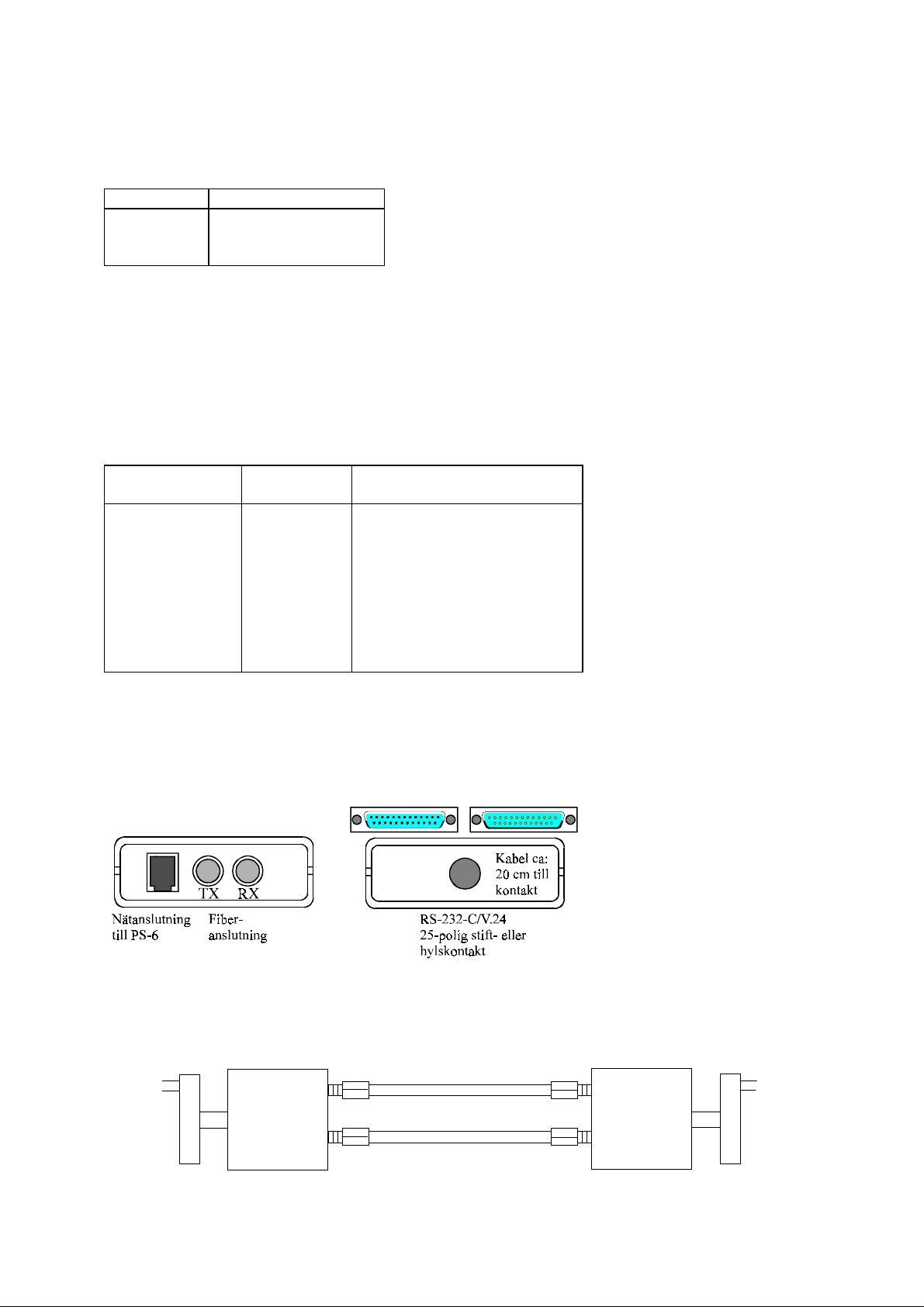
ANSLUTNINGAR • CONNECTIONS
BLOCKSCHEMA • BLOCK DIAGRAM
WESTERMO TELEINDUSTRI AB
6181-2001
© Westermo Teleindustri AB, 1997
e-mail: in fo@wes termo.se, www.westermo.se
Page 2

Specifikationer MM-61
Överföring: Asynkront/synkront*, Strömförsörjning: +5V DC, ±5% 300 mA via
full/halv duplex eller nätadapter PS-6
simplex Överföringshastighet: Upp till 38400 bit/s godtyckligt
Gränssnitt 1: EIA RS-232/CCITT V.24 för varje kanal samtidigt
25-polig D-sub, stift/hylsa Effektförbrukning: Max 7,0 VA vid 230V
omkopplingsbar mellan Temperaturområde: 5-50°C, omgivningstemperarur
DCE/DTE Fuktighetsområde: 0-95% RH utan kondensation
Gränssnitt 2: Se tabell för effektbudget, Mått: 60x22x98 mm ( BxHxD)
ST-kontakter Vikt: 0, 07 kg
Isolationsspänning: 3000V transformator Nätadapter: PS-6, 1,5 m kabel
( matning )
* Kablage behövs mellan ansluten utrustning och MM-61:ans D-sub.
Inställningar MM-61
MM-61 är ett 4-kanals fiberoptiskt modem. Det finns två versioner, 25-polig stift (male)
eller 25-polig hylsa (female) på RS-232-C sidan. För att anpassa MM-61 till omgivningen
finns det möjlighet att koppla om mellan DCE/DTE genom att lyfta på lådans lock
och skifta X1/X2. Lådans lock avlägsnas lättast t.ex. med ett mynt eller en skruvmejsel som föres
in och vrids i öppningarna mellan lock och botten.
'&(
;
;
6
5;
7;
'7(
S2 Linjesignal = Bygel (shunt)
123
Normal = Fabriksinställning
Inverterad
Effektbudget
Fiber 820 nm
S 2 V al av n o r m al e ll e r inve r te r ad
l in j e s ignal
X1/X2 Val av funktion D C E/DTE
(Kabeln placeras i önskad kontakt)
50/125 µm 3,7 dB
62.5/125 µ m 7,5 dB
200 PCS 18 dB
Page 3
Förluster i fiberoptisk kabel
Nedan angivna vär den kan variera beroen de på kvalité och fabrikat på den fiberoptiska kabeln.
Fiber Dämpning vid 820 n m
50/125 µm 3,0 dB/km
62.5/125 µ m 3,5 dB/km
200 PCS 6,0 dB/km
Typiska förluster i kont akter Typiska förluster i skarv
0,2-0,4 dB Svetsad 0,1 dB
Mekanisk 0,2 dB
Anslutningar MM-61
(25-polig D-sub hyl sdon eller 25-polig D-sub stift)
Riktning 1) Anslutning Beskrivning
DCE DTE
IO2TD1
OI3RD1
IO4TD2
OI5RD2
- 7 SG/Signal Ground
OI8RD3
I O 20 TD3
OI9RD4
I O 10 TD4
1) I = Ingång O = Utgång på MM-61. TD= Transmitted Data och RD= Received Data
OBS! De 4 kanalerna kan även användas för att överföra statussignaler typ RTS,CTS,DTR
eller för synkron överföring Transmit Clock ( pin 15 )( DCE ), Receive Clock ( pin 17 ) och
External Cl ock ( pin 24 )( DTE ).
Linjekoppling
MM-61
RX
TX
Kanal 1
MM-61
TX
RX
Kanal 1
Page 4

Specifications MM-61
Transmi ssion: Asynchronous/syn ch ronous*, Power supply: +5V DC, ±5% 300 mA via
full/half duplex or simplex mains adapter PS-6
Interface 1: EIA RS-232/CCITT V.24 Data rate: Up to 38 400 bit/s arbitrary for
25 pole D-sub connector each channel at the same time
male/female. Switch a ble Power consumption: Max 7.0 VA at 230V
between DCE/DTE Temperature range: 5-50°C ambient temperature
Interface 2: See table of power budget, Humidity: 0-95% RH without
ST-con n ectors condensation
Isolation: 3000V transformer Dimension: 60x22x98 mm ( WxHxD)
( Power Supply) Weight : 0.07 kg
Main adapter: PS-6, 1.5m cable
* Cable is required between conn ected equipment an d MM-61 25 pole D-sub connector.
Switch settings MM-61
The MM-61 is a 4-channel fibre optic modem. There are two versions, 25 pole male D-sub connector
or 25 pole female D-sub con n ector on the RS-232-C side. To adjust to the surrounding equipment
it is possible to select DCE or DTE function by r emoving the lid and shift X1/X2. The easiest
way to open the plastic case is by placing and turning a coin or screwdr iver in the gaps
between top and bottom.
'&(
;
;
6
5;
7;
'7(
S2 Signal on the line = Jumper
1 2 3 between modems
Normal = Factor y setting
Inverted
Power budget
Fibre 820 nm
S2 Selection of norm al or inverted signal
on the line between modem s
X1/X2 Selection of function DC E/DTE
(The cable is placed in required connector)
50/125 µm 3.7 dB
62.5/125 µ m 7.5 dB
200 PCS 18 dB
Page 5

Attenuation in fibre cable
The values below can differ depending on quality and manufacturer of the fibre optic cable.
Fibre Attenuation at 820 nm
50/125 µm 3,0 dB/km
62.5/125 µ m 3,5 dB/km
200 PCS 4,0 dB/km
Typical attenuation in connectors Typical attenuation in splice
0.2-0.4 dB Fusion 0.1 dB
Mechanical0.2 dB
Connections MM-61
(25 pole D-sub female or 25 pole D-sub male)
Direction 1) Connection no. Descr iption
DCE DTE
IO2TD1
OI3RD1
IO4TD2
OI5RD2
- 7 SG/Signal Ground
OI8RD3
I O 20 TD3
OI9RD4
I O 10 TD4
1) I = Input O = Output on MM-61. TD= Transmitted Data and RD= Received Data.
The 4 channels can also be used for transmitting handshake signals like RTS,CTS,DTR
or signals for synchronous transmission Tr an smit Clock ( pin 15 )( DCE ), Receive Clock ( p in 17 )
and External Clock ( pin 24 )( DTE ).
Line connection
MM-61
RX
TX
Ch. 1
MM-61
TX
RX
Ch. 1
Page 6

Tips
Några tips vid inkopplin g a v MM-61.
1. Kontrollera kabeln mellan ert RS-232
gränssnitt och RS-232 på MM-61. RS-232
gränssnittet på MM-61 är valbart mellan DCE
(Data Communication Equipment),
vilket är det van liga h os
kommunikation sutrustning ex. modem, och DTE
(Data Terminal Equipment), ex. PC, ter min aler
och skrivare. Nedan visas förslag till kablage
för att ansluta 4 st RS-232 utrustningar till en
MM-61.
Hur man kontrollerar om utrustningen är DCE
eller DTE:
- Spänningssätt den okända utrustningen och
kontrollera att ingenting är anslutet på RS-232
porten. Använd en multimeter och mät
spänningen på pin 2 i RS-232 kontakten
(hane eller hona) med r eferens till jord på pin 7
(25-polig) eller pin 5 (9-polig PC standard).
Mät sedan spänningen på pi n 3 på
samma sätt. Anslutningen med den mest
negativa spänningen är en utgång och
kommer att identifiera utrustningen som en
DCE eller DTE.
25-polig kontakt RS-232-C
• Om den mest negativa spänningen är på pin 2, är
utrustningen en DTE.
• Om den mest negativa spänningen är på pin 3, är
utrustningen en DCE.
9-polig kontakt PC standar d
• Om den mest negativa spänningen är på pin 3, är
utrustningen en DTE.
• Om den mest negativa spänningen är på pin 2, är
utrustningen en DCE.
Page 7

DC E , 25-p ol. D TE , 25-pol.
1
2
3
4
A
5
1
2
3
4
5
6
7
8
9
10
20
25
6
7
1
2
3
B
4
5
6
7
1
2
3
4
C
5
6
7
1
2
3
4
D
5
6
7
DC E , 25-p ol. D T E , 9-pol. PC
1
2
3
4
A
5
6
1
2
3
4
5
6
7
8
9
10
20
25
7
1
2
3
B
4
5
6
7
1
2
3
4
C
5
6
7
1
2
3
4
D
5
6
7
Page 8

Hints
Some hints on set-up of the MM-61.
1. Check the cable between your RS-232 interface
and the RS-232 on the MM-61. The RS-232
interface on the MM-61 can be configured as
DCE (Data Communication Equipment) or
DTE. Most printers, PCs and ter min als are set
as DTE (Data Ter min al Equipment). See
suggestions below of cable configuration to
connect four RS-232 equipments to a MM-61.
How to check whether the equipment is DTE
or DCE:
- Power up the unkn own equipment an d en sur e
that n oth ing is plugged into the RS-232
interface. Using a multi-meter, first measure
the
voltage on pin 2 of the connector (male or
female) with r eference to ground on pin 7 (25
pole connector) or on pin 5 (9 pole connector,
PC standard). Then measur e the voltage on
pin 3 in the same way. The pin with the most
negative voltage will be output pin and will
identify the device as DCE or DTE.
25 pole connector RS-232-C
• If the most negative voltage is on pin 2:
the device is DTE.
• If the most negative voltage is on pin 3:
the device is DCE.
9 pole connector,PC standa rd
• If the most negative voltage is on pin 3:
the device is DTE.
• If the most negative voltage is on pin 2:
the device is DCE.
DC E , 25 pole DTE , 25 pole
1
2
3
4
A
5
1
2
3
4
5
6
7
8
9
10
20
25
6
7
1
2
3
B
4
5
6
7
1
2
3
4
C
5
6
7
1
2
3
4
D
5
6
7
DC E , 25 pole DT E , 9 pole P C
1
2
3
4
A
5
6
1
2
3
4
5
6
7
8
9
10
20
25
7
1
2
3
B
4
5
6
7
1
2
3
4
C
5
6
7
1
2
3
4
D
5
6
7
Page 9

Block diagram
DCE
Pin/
soc k et
2
3
4
5
8
9
10
20
7
DTE
Pin/
soc k et
2
3
4
5
8
9
10
20
7
TX
MUX
RX
DEMUX
SG
Channel 1: 2-3
Channel 2: 4-5
Channel 3: 8-20
Channel 4: 9-10
Distri butors
Wester mo Teleindustri AB har återförsäljare i följan de länder, kontakta oss för mer information.
Westermo Teleindustri AB have distributor s in followin g countries, contact us for further information.
Austria
Finland
Italy
Belgium
France
Netherlands
Czech Republic
Germany
Norway
Denmark
Great Britai n
Switzerland
Westermo Teleindustri AB, S-640 40 Stora Sundby, Sweden, Ph one +46 16 612 00, Fax + 46 16 611 80
Westermo Web site www.westermo.se , e- mail: in fo@westermo.se
 Loading...