

Page 1
Omvandlare Opto – RS-422/485/V.11
Converter Opto – RS-422/485/V.11
Glasfaser Wandler – RS-422/485/V.11
INSTALLATIONSANVISNING
INSTALLATION MANUAL
INSTALLATIONS ANLEITUNG
6071-2022
www.westermo.se
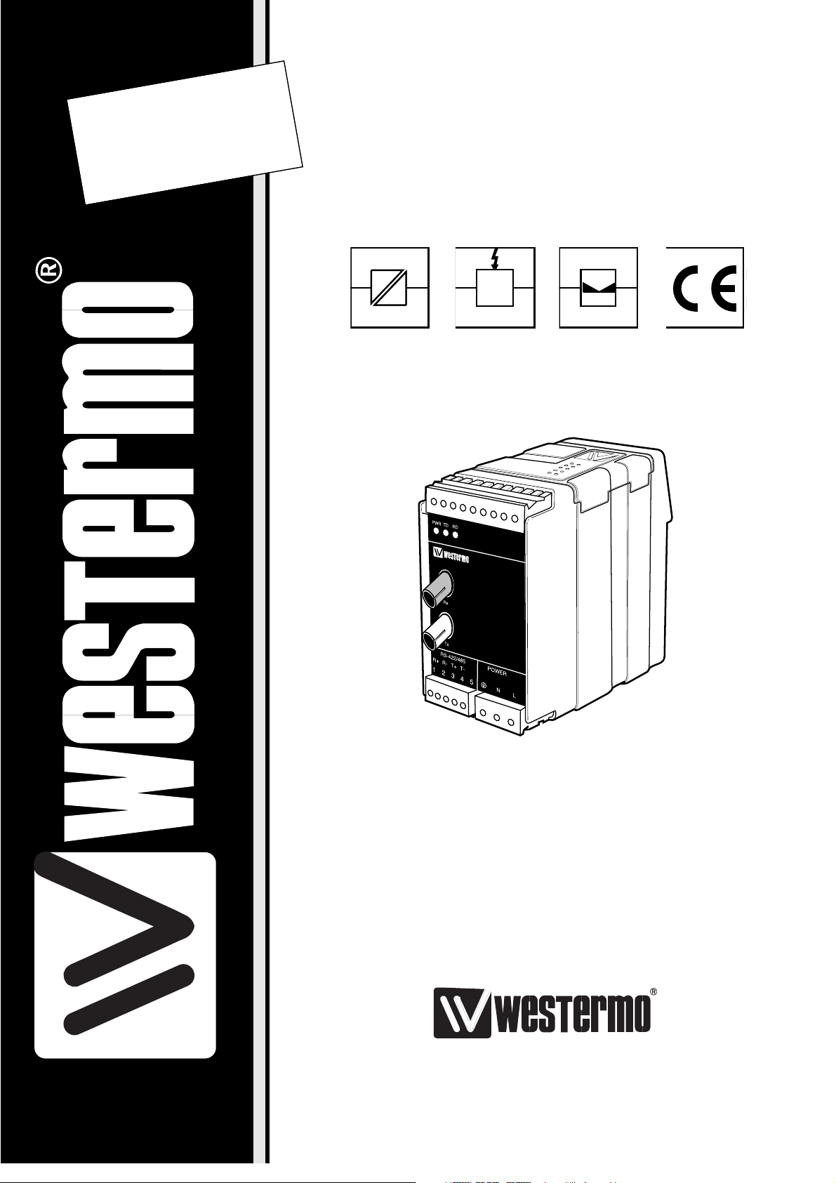
MD-63B AC
MD-63B DC
©
Westermo Teleindustri AB • 1999 • REV. B
Galvanic
Isolation
Transient
Protection
Balanced
TransmissionCEApproved
MD-63
Page 2

8 6071-2022
Specifikations MD-63B
Transmission Synchronous, full/half duplex or simplex
Interface 1 EIA RS-422/RS-485
CCITT V.11, 5-position detachable screw-terminal
Interface 2 See table of power budget, ST-connectors
Surge protection Mains: breakdown voltage 430V at 230V AC
och 220 V vid 115V AC**
Interface 1: transient protection
flashover voltage for receiver and transmitter
7V. Dissipation capability 0.6 kW for 1 ms.
Power supply 115V*/230V AC
+15/–10% 48-62 Hz
12-36V DC**
Fuse 100 mA fast 5x20 mm
1.6 A fast 5x20 mm**
Data rate 500 kbit/s to 4 Mbit/s Manchester code***
Indicators Power, TD, RD
Power consumption Max 4 VA at 115V* and 230V AC. Max 3 W**
Temperature range 5-50°C, ambient temperature
Humidity 0-95% RH without condensation
Dimension 55x100x128 mm (WxHxD)
Weight 0.4 kg
Mounting On 35 mm DIN-rail
* MD-63B 115V only
** MD-63B DC only
*** For higher data rate, please contact Westermo.
Description MD-63B
MD-63B allows point to point communication and conversion between RS-422/485 and
fibre. The modem is developed for Manchester coded protocols with transmission rates
over 500 kbit/s. Transmission distances up to 25 km is possible. The modem consists of
one fibre channel with separate transmitter and receiver. On the front of the unit there
are five LED’s that indicates the data transmission on the channel.
Page 3
96071-2022
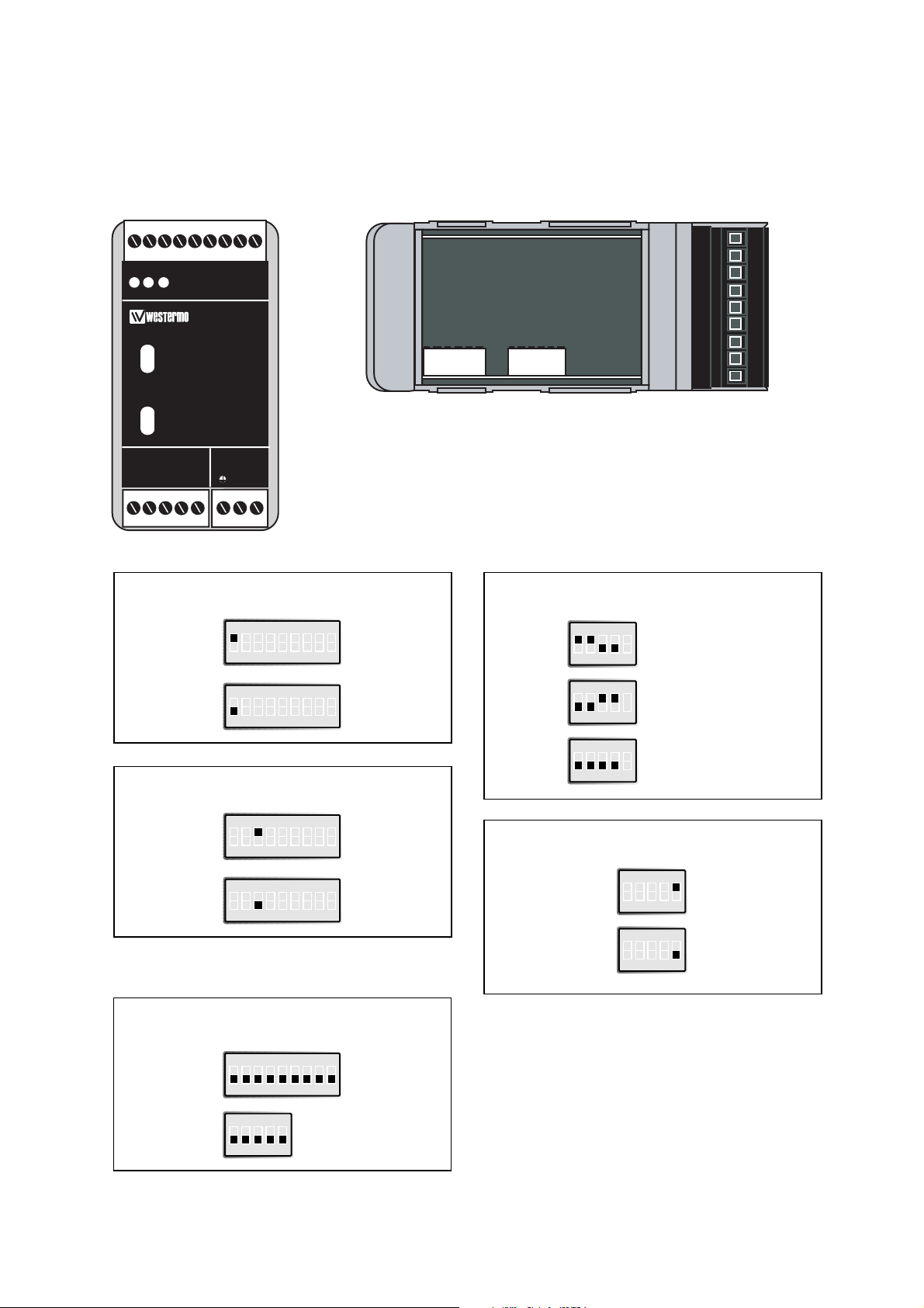
Switch settings MD-63B
The MD-63B can through different switch settings be adapted to a variety of running
conditions. To set the switches,open the plastic case by removing the top cover.
Selection of 2- or 4-wire
S1 4-wire
ON
123456789
S1 2-wire
ON
123456789
Selection of speed
S1
Over 1 Mbit/s
ON
123456789
S1
Under 1 Mbit/s
ON
123456789
Factory settings
S1
ON
123456789
S1: 2 and 4-9 not used
Termination with fail-safe 1)
S2
ON
12345
Termination (2-wire)
S2
ON
12345
Termination (4-wire)
S2
ON
12345
No termination
Transmitted power
S2
ON
12345
Low
S2
ON
12345
High
S2
ON
12345
1) The fail-safe function forces the signal
state of the receiver to OFF when the
connected transmitter is in tri-state
(transmitter inactive). The receiver
located furthest away shall be
terminated.
123456789
TD RDPWR
MD-63
Rx
Tx
RS-422/485 POWER
R+
R- T+ T-
12345 LN
S1:1-9
S2:1-5
Page 4

10 6071-2022
Screw Power
No. supply
L 115*/230V
N AC power
Protective earth
Connection MD-63B
Line connection
(5-position screw terminal)
Power connection
MD-63B DC
2-position screw terminal
Direction Connection CCITT V.11
No. Description
Receiver 1 A’
Receiver 2 B’
Transmitter 3 A
Transmitter 4 B
5 Shield
Connection Power
no. supply
1 – Voltage
2 + Voltage
Power connection
MD-63B AC
3-position screw terminal
* MD-63B 115V only
Page 5

116071-2022
Line connection
1) If screened cable is used, only connect the screen in one terminal to avoid ground current.
TX
3
4
1
2
5
Equipment with
fibre optic
Equipment with
RS-422/V11
RX
TX TD
RD
Shield 1)
RX
RD
TD
TX
3
4
5
Equipment with
fibre optic
Equipment with
RS-485
RX
TX
TD/RD
Shield 1)
RX TD/RD
MD-63B
MD-63B
A’
A/A’
B/B’
B’
A
B
Page 6

12 6071-2022
Power budget
The MD-63B is designed to be used with Manchester coded protocols. This means that the
power budget varies depending on the number of preamble bits in the protocol. Preamble
bits are transmitted before the actual data and are used in order to synchronise the receivers
in the network. (see figure below)
The MD-63B uses these preamble bits as well to stabilise its receiver. This does mean that
a 10% distortion is applied to the preamble bits through the MD-63B. The diagrams show
the available power budget dependent on number of preamble bits. Please be aware that we
are quoting minimum guaranteed power budget. Experience has shown that the typical values
will be 4dBm higher for 820nm, 3.5dBm
higher for 1300nm and 6dBm higher
for single mode.
Idle line 3 preamble bits Start sending data
(Manchester coded)
16
14
12
10
8
6
4
2
0
0 500 1000 1500 2000 2500 3000 3500 4000 4500
20 bits
preamble
10 bits
preamble
1 bit
preamble
2 bits
preamble
Power budget (dBm)
Transmission speed (kbit/s)
Minimum guaranteed budget 820nm, 62.5/125µm fibre
Minimum guaranteed budget 1300nm, 62.5/125µm fibre
14
12
10
8
6
4
2
0
0 500 1000 1500 2000 2500 3000 3500 4000 4500
20 bits
preamble
10 bits
preamble
1 bit
preamble
2 bits
preamble
Power budget (dBm)
Transmission speed (kbit/s)
Page 7

136071-2022
Minimum guaranteed budget single mode, 9/125µm fibre
7
6
5
4
3
2
1
0
0 500 1000 1500 2000 2500 3000 3500 4000 4500
20 bits
preamble
10 bits
preamble
1 bit
preamble
2 bits
preamble
Power budget (dBm)
Transmission speed (kbit/s)
Fibre Attenuation Attenuation Attenuation
at 820 nm at 1300 nm at single mode (1300 nm)
50/125 µm 3.0 dB/km 1.0 dB/km
62,5/125 µm 3.5 dB/km 1.2 dB/km
100/140 µm 4.0 dB/km
9/125 µm 0.5 dB/km
Attenuation in fibre cable
The values below can differ depending on quality and manufacturer of the fibre-optic
cable.
Attenuation in connectors Attenuation in splice
0.2-0.4 dB Fusion 0.1 dB
Mecanical 0.2 dB
Page 8

6071-2022 05.99
Westermo Teleindustri AB • S-640 40 Stora Sundby, Sweden
Phone +46 16 612 00 Fax +46 16 611 80
E-mail: info@westermo.se • Westermo Web site: www.westermo.se
Westermo Teleindustri AB have distributors in several countries,
contact us for further information.
Westermo Data Communications GmbH
Bruchsaler Straße 18, 68753 Waghäusel
Tel.: +49(0)7254-95400-0 • Fax.:+49(0)7254-95400-9
E-Mail: westermo.germany@t-online.de
Westermo Data Communications Ltd
Solent Business Centre • Millbrook Road West
Millbrook, Southampton • SO15 0HW
Phone: +44(0)1703-704 611 • Fax.:+44(0)1703 702 682
E-Mail: sales@westermo.co.uk
Subsidiaries
Block diagram
 Loading...