

Page 1
Omvandlare Opto – RS-485
Converter Opto – RS-485
Glasfaser Wandler – RS-485
INSTALLATIONSANVISNING
INSTALLATION MANUAL
INSTALLATIONS ANLEITUNG
6071-2071
www.westermo.se
MD-63
Profibus
©
Westermo Teleindustri AB • 2001 • REV. B
Galvanic
Isolation
Transient
Protection
Balanced
Transmission
CE
Approved
Page 2

8 6071-2071
Functional description MD-63 Profibus
MD-63 Profibus is developed for RS-485 point-to-point communication and conversion
between RS-485 and fibre. The unit is specially developed for Profibus and uses a
Profibus standard 9-position D-sub for connection with RS-485. Possibility to connect
to a 5-position screw block is also available.
The fibre optic interface uses ST-connectors and both multi mode and single mode
fibre versions are available. The maximum transmission distance is calculated from the
available power budget of the modems and the attenuation of the cable, splice joints and
connectors. Distances up to 25 km can be reached using single mode fibres. The fibre
optical cable is completely immune to external interference, which makes it ideal for
harsh enviroments.
The modem consists of one F/O channel with separate transmitter and receiver.
On the front of the unit there are also three LED’s indicating the data transmission
on the channel.
MD-63 Profibus can be used at all standard Profibus transmission speeds up to 1.5 Mbit/s
and all operating parameters are set-up via DIP switches easily assessable under the lid
on the top of each unit.
MD-63 Profibus is available in low (LV) and highvoltage (HV) versions. MD-63LV
supports power supplies 12–45V AC ± 5% and 12-55V DC ± 5%. MD-63HV
supports power supplies 95–240V AC ± 5% and 110–240V DC ± 5%
Page 3
96071-2071
Specifications MD-63 Profibus
Transmission Asynchronous, full/half duplex or simplex
Interface 1 EIA RS-485 / ITU-T V.11 Profibus standard 9-position
D-sub alt. 5-position screw block
Interface 2 Fibre optical 2 ST-connections
Data rate 9.6, 19.2, 93.75, 187.5, 500, 1500kbit/s
Indicators PWR, TD, RD, LINK
Temperature range 5–50°C ambient temperature
Humidity 0–95% RH without condensation
Dimension 55x100x128 mm (WxHxD)
Weight 0.4 kg
Mounting On 35mm DIN-rail
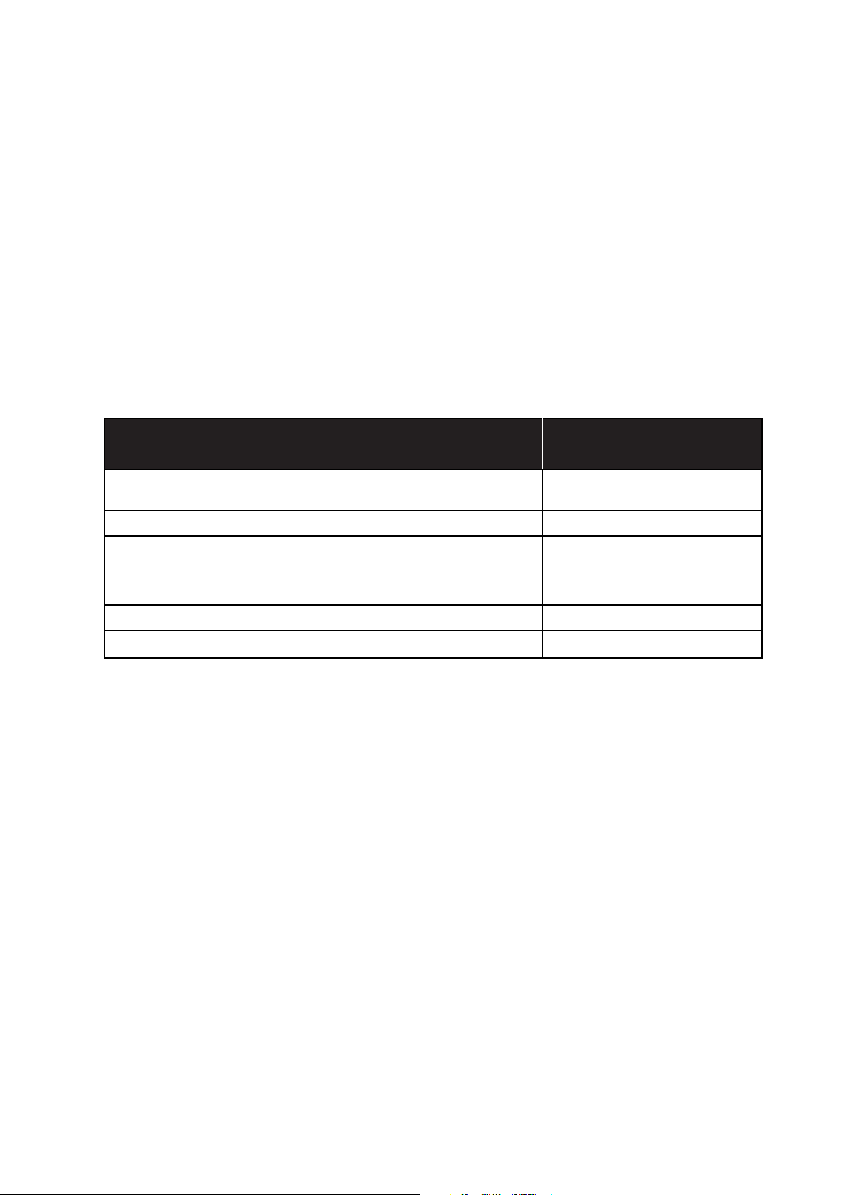
Power supply alternatives
Model description
MD-63HV MD-63LV
PROFIBUS PROFIBUS
Power supply 95–240V AC ± 10% / 12–45V AC ± 10% /
110–240V DC ± 10% 12–55V DC ± 10%
Frequency 48–62Hz / – 48–62Hz / –
Fuse, F1 1A T / 1A T 1A T / 1A T
Wickmann Wickmann
Power consumption 40 mA 3W
Overvoltage protection 430V 430V
Isolation, RMS 3 750V 3 750V
LEDs for indication on MD-63 Profibus
• PWR: Indicates that the unit has power
• TD: Indicates recevied data on Profibus/RS-485 side.
• RD: Indicates transmitting data on Profibus/RS-485 side.
• LINK: Indicates a fibre optic link between the modems.
Page 4

10 6071-2071
Switch settings MD-63 Profibus
Factory settings
ON
123456789
ON
12345
S2
S1
Selection of data rate
Selection of Link-detect
ON
123456789
S1
The fail-safe function forces the received signal to inactive
state when the connected transmitter is in tri-state (transmitter inactive).
Link detect means that the fibre optic channel is continuously analysed. When an acceptable level is detected this
will be indicated with the LINK-Led.
Selection of
termination resistor
ON
12345
S2
Termination cable type A (220Ω)
ON
12345
S2
Termination cable type B (150Ω)
See cable types page 12
Selection of
transmitted power
ON
12345
S2
Low
ON
12345
S2
High
Turning
time
auto detect
ON
123456789
S1
9,6 kbit/s
ON
123456789
S1
Inactivated
ON
123456789
S1
Aktivated
ON
123456789
S1
19,2 kbit/s
ON
123456789
S1
93,75 kbit/s
ON
123456789
S1
187,5 kbit/s
ON
123456789
S1
500 kbit/s
ON
123456789
S1
1500 kbit/s
Selection of termination
with fail-safe
ON
12345
S2
No termination
ON
12345
S2
Termination
S1:1-9
S2:1-5
Page 5

116071-2071
50/125 µm 3.0 dB/km 1.0 dB/km
62.5/125 µm 3.5 dB/km 1.2 dB/km
100/140 µm 4.0 dB/km
9/125 µm 0.5 dB/km
Fibre
Attenuation
at 820 nm
Attenuation
at 1300 nm
Attenuation
at single mode (1300 nm)
Attenuation in fibre cable
The values below can differ depending on quality and manufacturer of the fibre-optic
cable.
Attenuation in connectors Attenuation in splice
0.2–0.4 dB Fusion 0.1 dB
Mechanical 0.2 dB
50/125 16.6 dB 14.6 dB
62.5/125 18.6 dB 15.1 dB
100/140 25.9 dB
9/125 12.3 dB
50/125 10.7 dB 8.1 dB
62.5/125 14.5 dB 11.6 dB
100/140 20.6 dB
9/125 6.3 dB
Unit
820 nm 1300 nm single mode
Unit
820 nm 1300 nm single mode
Min. budget Typ. budget
Power budget
”Min. budget” states the minimum guaranteed power budget. Experience shows however that the
typical value is in the range of the indicated ”Typ. budget”.
Fibre
Fibre
Page 6

12 6071-2071
Connections MD-63 Profibus
MD-63 Profibus is specially developed for communication to units communicating with Profibus-DP or
FMS. The connection is easily made via a Profibus
cable connected to the 9-position D-sub on the unit.
Possibility to connect to a 9-position screw block is
also available.
Line connection
Connections
Cable types
Designation 9-pos D-sub 9-pos screw block Description
T/R-P 3 8 Line connection – P
T/R-N 8 7 Line connection – N
VP 6 9 +5V supply
DGND 5 6 Signal ground
Designation Impedance Capacity Resistance Conductor area
Cable type A 135–165Ω (3–20MHz) <30pF/m <110Ω/km ≥0,34 mm2(22AWG)
Cable type B 100–130Ω (>100kHz) <60pF7m – ≥0,22 mm
2
(24AWG)
Connection example
123456789
123456789
Profibus-DP/FMS
Profibus DP/FMS
Connection to 9-pos D-sub
Connection to screw block
123456789
Page 7

136071-2071
Screw no. Power supply
1 – Low voltage
2 + Low voltage
Connection Power supply
L – High voltage
N + High voltage
O Protective earth
Power connections
Connection MD-63LV Profibus Connection MD-63HV Profibus
2-position screw-terminal 3-position screw-terminal
Fibre optical connection
Connection example
Profibus-DP/FMS
MD-63
Profibus
RD
TD
RD
TD
MD-63
Profibus
Profibus-DP/FMS
Transmitter (TD)
Receiver (RD)
123456789
Page 8

6071-2071 01-11 Mälartryck AB, Eskilstuna, Sweden
Application example
CHANNEL 3
PWR
RD
TD
DCD2
DCD3
DCD4
CHANNEL 2 POWER
LD-01 DC
CHANNEL 4
123456789123456789
R+ R- T+ T- T+ T- R+ R-
CHANNEL 3
PWR
RD
TD
DCD2
DCD3
DCD4
CHANNEL 2 POWER
LD-01 DC
CHANNEL 4
123456789123456789
R+ R- T+ T- T+ T- R+ R-
Profibus-
DP/FMS
ProfibusDP/FMS
ProfibusDP/FMS
Fibre
Westermo Teleindustri AB • SE-640 40 Stora Sundby, Sweden
Phone +46 16 42 80 00 Fax +46 16 42 80 01
E-mail: info@westermo.se • Westermo Web site: www.westermo.se
Westermo Teleindustri AB have distributors in several
countries, contact us for further information.
Westermo Data Communications Ltd
Unit 14 Talisman Business Centre • Duncan Road
Park Gate, Southampton • SO31 7GA
Phone: +44(0)1489 580 585 • Fax.:+44(0)1489 580586
E-Mail: sales@westermo.co.uk • Web: www.westermo.co.uk
Westermo Data Communications GmbH
Goethestraße 67, 68753 Waghäusel
Tel.: +49(0)7254-95400-0 • Fax.:+49(0)7254-95400-9
E-Mail: info@westermo.de • Web: www.westermo.de
Westermo Data Communications S.A.R.L.
9 Chemin de Chilly 91160 CHAMPLAN
Tél : +33 1 69 10 21 00 • Fax : +33 1 69 10 21 01
E-mail : infos@westermo.fr • Site WEB: www.westermo.fr
Subsidiaries
 Loading...