

Page 1
Omvandlare, optisk fiber
– RS-422/485/V.11
Converter, fibre-optic
– RS-422/485/V.11
Glasfaser Wandler
– RS-422/485/V.11
INSTALLATIONSANVISNING
INSTALLATION MANUAL
INSTALLATIONS ANLEITUNG
6071-2002
www.westermo.se
MD-63 AC
MD-63 DC
©
Westermo Teleindustri AB • 2000• REV. B
Galvanic
Isolation
Transient
Protection
Balanced
Transmission
CE
Approved
MD-63
Page 2

8 6071-2002
Specifications MD-63
Transmission Asynchronous*, full/half duplex or simplex
Interface 1 EIA RS-422/485
CCITT V.11, 5-position detachable screw-terminal
Interface 2 ST-connectors, see table of power budget
Data rate Up to 1.5 Mbit/s
Indicators Power, TD, RD
Temperature range 5–50°C, ambient temperature
Humidity 0–95% RH without condensation
Dimensions 55x100x128 mm (WxHxD)
Weight 0.45 kg AC / 0.3 kg DC
Mounting On 35 mm DIN-rail
Power supply alternatives
Functional description MD-63
MD-63 is developed for RS-422/485 point to point communication via fibre optic cables.
Transmission rates up to 1.5 Mbit/s and transmission distances up to 25 km is possible.
The MD-63 consists of one F/O channel with separate transmitter and receiver, Tx and
Rx. On the front of the unit there are also three LED’s indicating the data transmission
on the channel. The fibre optical cable is completely immune to external interference,
which makes it ideal for harsh environments.
Model description
MD-63 MD-63 MD-63 MD-63
AC 115V AC DC 36–55V DC
Power supply 230V AC 115V AC 24V DC 48V DC
+15/–10% +15/–10% +50/–50% +15/–25%
Frequency 48–62Hz 48–62Hz – –
Fuse, F2 100mA S 100mA S 1.6A S 1.6A S
5x20 mm 5x20 mm 5x20 mm 5x20 mm
Littelfuse Littelfuse Littelfuse Littelfuse
Power consumption 5VA 5VA 3W 3W
Overvoltage protection 430V 220V – –
Isolation 1 500V 1 500V 500V 500V
RMS
* Synchronous protocols can be transmitted under certain circumstances.
See ”selection of bits” page 10.
Page 3
96071-2002
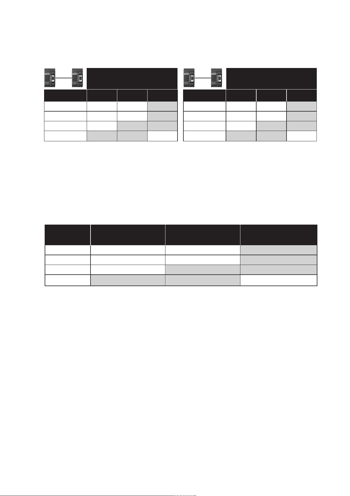
50/125 µm 3.0 dB/km 1.0 dB/km
62.5/125 µm 3.5 dB/km 1.2 dB/km
100/140 µm 4.0 dB/km
9/125 µm 0.5 dB/km
Fibre
Attenuation
at 820 nm
Attenuation
at 1300 nm
Attenuation
at single mode (1300 nm)
Attenuation in fibre cable
The values below can differ depending on quality and manufacturer of the fibre-optic
cable.
Attenuation in connectors Attenuation in splice
0.2–0.4 dB Fusion 0.1 dB
Mecanical 0.2 dB
50/125 16.6 dB 14.6 dB
62.5/125 18.6 dB 15.1 dB
100/140 25.9 dB
9/125 12.3 dB
50/125 10.7 dB 8.1 dB
62.5/125 14.5 dB 11.6 dB
100/140 20.6 dB
9/125 6.3 dB
Unit
820 nm 1300 nm single mode
Unit
820 nm 1300 nm single mode
Min. budget Typ. budget
Power budget
”Min. budget” states the minimum guaranteed power budget. Experience shows however that the
typical value is in the range of the indicated ”Typ. budget”.
Fibre
Fibre
Page 4

10 6071-2002
Switch settings MD-63
The MD-63 can through different
switch settings be adapted to a
variety of running conditions. To
set the switches, open the plastic
case by removing the top cover.
Selection of Turning time/
Transmission rate
0.4 ms ≤ 2 400 bit/s
Turning
time
Transmission
rate
ON
123456789
S1
0.2 ms 4 800 bit/s
ON
123456789
S1
0.1 ms 9 600 bit/s
ON
123456789
S1
75 µs 14 400 bit/s
ON
123456789
S1
50 µs 19 200 bit/s
ON
123456789
S1
37 µs 28 800 bit/s
ON
123456789
S1
25 µs 38 400 bit/s
ON
123456789
S1
16 µs 62 500 bit/s
ON
123456789
S1
11 µs 93 750 bit/s
ON
123456789
S1
9 µs 115.2 kbit/s
ON
123456789
S1
6 µs 187.5 kbit/s
ON
123456789
S1
3 µs 375 kbit/s
ON
123456789
S1
2 µs 500 kbit/s
ON
123456789
S1
1 µs 1–1.5 Mbit/s
ON
123456789
S1
Selection of 2- or 4-wire
S1 4-wire
ON
123456789
S1 2-wire
ON
123456789
S1: 2-3 not used
Selections of bits
S1
9
ON
123456789
S1
10
ON
123456789
S1
11
ON
123456789
S1
*
ON
123456789
*) Use this setting for synchronous protocols.
The transmitter will be active from the start bit
to 10 bit-times after the last high databit
(see example below).
The speed shall be set to ≅10 times
the required communication speed.
Start bit
1 bit = 52µs
1 bit: 1/1 9200 = 52µs
Data rate 19 200
Transmitter active
Set the speed to 187.5 kbit/s
10x52µs = 520µs
↵
Example 19 200 bit/s
S1:1-9
S2:1-5
Page 5

116071-2002
••• •
•• • •
•••
••• •
•••
•••
10 10 10 11 11 119
Supervision table when selecting data bits
7 bits
8 bits
No parity
Parity
1 stop bit
2 stop bits
Number of bits
Factory settings
S1
ON
123456789
Termination with fail-safe
S2
ON
12345
Termination (2-wire)
S2
ON
12345
Termination (4-wire)
S2
ON
12345
No termination
Transmitted power
S2
ON
12345
Low
S2
ON
12345
High
S2
ON
12345
The fail-safe function forces the signal state of the receiver
to OFF when the connected transmitter is in tri-state
(transmitter inactive). The receiver located furthest away
shall be terminated.
Page 6

12 6071-2002
Connection Power
No. supply
L 115*/230V
N AC power
PE/Protective Earth
Connections MD-63
Line connection
(5-position screw-terminal)
Power connection
MD-63 DC
(2-position screw-teminal)
Direction Connection CCITT V.11
No. Description
Receiver 1 A’ (R+)
Receiver 2 B’ (R–)
Transmitter 3 A (T+)
Transmitter 4 B (T–)
5 Shield
Connection Power
No. Supply
1 – Voltage
2 + Voltage
Power connection
MD-63 AC
(3-position screw-terminal)
* Only MD-63 115V
The definations R+/R–,T+/T– can be various between
different manufactures.
Fibre connection
MD-63
TX
RX
TX
RX
MD-63
TD RDPWR
MD-63
Rx
Tx
RS-422/485 POWER
R+
R- T+ T-
12345 LN
Page 7

136071-2002
How to connect
1) If shielded wire is used, connect shield only in one end to avoid ground loop currents.
TX
5
R+ R– T– T+
Equipment with
fibre-optic
Equipment with
RS-422/V11
RX
TX
R+
R–
T+
T–
T+
T–
R+
R–
Shield 1)
= Termination
RX
TX
5
Equipment with
fibre-optic
Equipment with
RS-485
RX
TX
Shield 1)
RX
MD-63
MD-63
= Termination
1
2
3
4
T–/R– T+/R+
T+/R+
T–/R–
T+/R+
T–/R–
Hints
RS-422/485 were designed for multidrop applications. When a system is installed it
should form a bus structure.
Star shaped networks should never be created, there are other Westermo products
designed to work in star net applications. To correctly install, an RS-422/485 network
should be terminated at the correct points.
The recommendation is to terminate the receiver on the first unit and the final bus
unit. See diagrams under the headline ”Line connection” for details of how this is done
with RS-485 (2 wire) and RS-422 (4 wire).
If any problems do occur on set up of the MD-63, the LEDs will be helpful.
• PWR: The unit has power.
• RD: Data received on the opto interface.
• TD: Data received on the RS-422/485 interface.
4
3
N.B. R+/R–, T+/T– definitations are not standard, it can help to shift A and B
if the unit does not work.
Page 8

6071-2002 01.03 Mälartryck AB, Eskilstuna, Sweden
Westermo Teleindustri AB • S-640 40 Stora Sundby, Sweden
Phone +46 16 42 80 00 Fax +46 16 42 80 01
E-mail: info@westermo.se • Westermo Web site: www.westermo.se
Westermo Teleindustri AB have distributors in several countries,
contact us for further information.
Westermo Data Communications GmbH
Bruchsaler Straße 18, 68753 Waghäusel
Tel.: +49(0)7254-95400-0 • Fax.:+49(0)7254-95400-9
E-Mail: info@westermo.de • Web: www.westermo.de
Westermo Data Communications Ltd
Unit 14 Talisman Business Centre • Duncan Road
Park Gate, Southampton • SO31 7GA
Phone: +44(0)1489 580 585 • Fax.:+44(0)1489 580586
E-Mail: sales@westermo.co.uk • Web: www.westermo.co.uk
Subsidiaries
Block diagram
 Loading...