

Page 1
CTS-generator,
Xon/Xoff till CTS-omvandlare
CTS-generator,
Xon/Xoff to CTS converter
CTS-Generator,
Xon/Xoff auf CTS Wandler
INSTALLATIONSANVISNING
INSTALLATION MANUAL
INSTALLATIONS ANLEITUNG
6605-2001
www.westermo.se
MD-54 AC
MD-54 DC
©
Westermo Teleindustri AB • 1999 • REV. A
Galvanic
Isolation
Transient
Protection
Balanced
TransmissionCEApproved
Page 2

136605-2001
Specifications MD-54
Transmission Asynchronous, full/half duplex or simplex
Interface Channel 3: RS-232/V.24: 5-pin screw terminal
Channel 0: RS-232/V.24: 9-pin D-sub
RS-422/485: 5-pin screw terminal
Transmission rate Channel 3: 300–115 200 bit/s
Channel 0: RS-232/V.24: 1 200–115 200 bit/s
RS-422/485: 1 200–460 800 bit/s
Buffer Channel 3: 16 kb
Channel 0: 16 kb
Power supply 230V AC +15%/–10% 48–62 Hz, 12–36V DC
Isolation voltage 3000V AC, 1500V DC
Fuse AC 100mA fast 5x20 mm, DC 1.6A
LED Indicators PWR, RD0, TD0, L1, L2, L3, L4, L5, L6, L7, L8
Power consumption AC 30 mA, DC 1.5W
Temperature range 5–50°C, ambient temperature
Humidity 0–95% RH non-condensing
Dimension 55x100x128 mm (WxHxD)
Weight AC 0.5 kg, DC 0.3 kg
Mounting 35 mm DIN-rail
Description MD-54
The MD-54 is a device that solves serial data incompatibility problems between two
devices. For example it can be used as a ’CTS-generator’ or a ’XON/XOFF to RTS/CTSconverter’. It can also be used as a parameter and/or speed-converter and data buffer.
The unit is set up using a terminal or PC and settings are stored in non volatile memory.
The unit consists of two RS-232/V.24 interfaces and two 16 kb data buffers, one in
each direction. There is also a RS-422/485 interface connected in parallel to one of the
RS-232/V.24 interfaces. Both RS-232/V.24 interfaces are DCE connections.
The front cover has 11 LED’s for status indication.
As with other Westermo products the MD-54 provides a high level of galvanic isolation both on power and inputs. Operating modes are set-up via DIP-switches located
under the lid on the top of the unit. The MD-54 is available in both AC (230V) and DC
(12–36V) supply voltage. The unit is designed for mounting on 35 mm DIN-rail.
Page 3
14 6605-2001
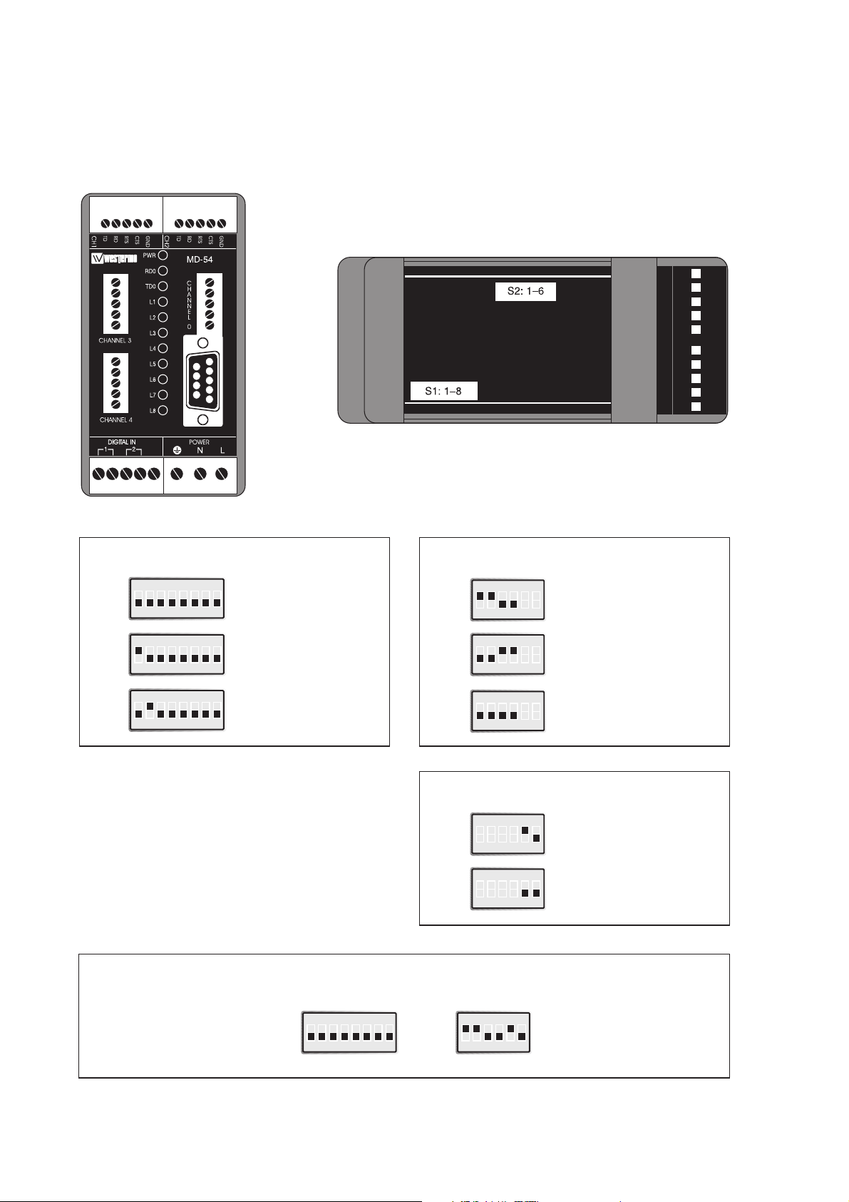
Switch settings MD-54
The MD-54 can be set for a range of different operating conditions. Some settings are
made via DIP-switches located under the lid on the top of the unit.
ON
12345678
ON
123456
5
4
3
2
1
5
4
3
2
1
1
2
3
4
5
1234 5 123 45
Warning! Do not open
connected unit
Function switch 1
Normal function
S1
ON
12345678
New program can
be downloaded
via channel 0 *
S1
ON
12345678
Settings can be made
via channel 0 **
S1
Function switch 2
Termination 4-wire (RS-422)
S2
ON
123456
Termination 2-wire (RS-485)
S2
ON
123456
No termination
S2
ON
123456
Function switch 2
Factory settings
4-wire (RS-422)
S2
ON
12345678
S1
ON
123456
S2
ON
123456
2-wire (RS-485)
S2
*) The unit will automatically adapt its communication
parameters for channel 0.
PC based software from Westermo is required to download a new program.
**) In this setting channel 0 communicates as follow:
– 9 600 bit/s
– 8 bits wordlength
– no parity
– 1 stop bit
Page 4
156605-2001
Designation Description
PWR Power supply OK
RD0 RD signal channel 0
TD0 TD signal channel 0
L1 RTS signal channel 0
L2 –
L3 CTS signal channel 3
L4 –
L5 RD signal channel 3
L6 TD signal channel 3
L7 RTS signal channel 3
L8 –
Connections MD-54
Direction Connection CCIT V.11
no. Description
Receiver 1 A’ (R+)
Receiver 2 B’ (R–)
Transmitter 3 A (T+)
Transmitter 4 B (T–)
5 Shield
Connection channel 0, RS-422/485 LED’s description
Direction Connection CCITT V.24
Signal description
DCE 9-pos D-sub Description
O 2 104 RD/Received Data
I 3 103 TD/Transmitted Data
– 5 102 SG/Signal Ground
I 7 105 RTS/Request To Send
O 8 106 CTS/Clear To Send
I = Input MD-54 O = Output MD-54
Connection channel 0, RS-232/V.24
Direction Connection CCITT V.24
Signal description
DCE no. Description
I 1 103 TD/Transmitted Data
O 2 104 RD/Received Data
I 3 105 RTS/Request To Send
O 4 106 CTS/Clear To Send
– 5 102 SG/Signal Ground
I = Input MD-54 O = Output MD-54
Connection channel 3, RS-232/V.24
Digital In, channel 1, 2 and 4 not used.
The definations R+/R–, T+/T– can be various between
different manufactures.
Page 5

16 6605-2001
Power connection
MD-54 DC
2-position screw-terminal
Connection Power
supply
– – Voltage
+ + Voltage
Screw Power
supply
L 230V
N AC power
Earth
Power connection
MD-54 AC
3-position screw-terminal
Line connection
Transmission range (RS-422/485)
Use twisted pair cable. Max transmission range 1200 metre.
(cable specifications 0.3 mm
2
and capacitance 42pF/m).
The transmission range will increase if a cable with lower capacitance and larger
diameter is used.
Use shielded cable in heavy industrial environments.
1) If shielded cable is used, connect the shield only at one end to avoid ground currents.
Receiver
Transmitter
Shield
MD-54
1
2
3
4
1)
5
A’
B’
A
B
Twisted pairs
RS-422
equipment
A
Transmitter
B
A’
Receiver
B’
RS-485RS-422
MD-54
Transmitter/
Receiver
Shield
3
A/A’
4
1)
B/B’
5
Twisted pairs
A/A’
B/B’
RS-485
equipment
Transmitter/
Receiver
Page 6

176605-2001
How to make settings through a terminal
1. Make sure the power is off (’PWR’ LED off).
2. Connect communication-cable between CH0 (D-sub) and terminal.
3. Set switch 1:2 ON
4. Connect power cable
A menu should appear on the screen. It is now possible to make settings.
After settings have been made:
5. Disconnect power
6. Set switch 1:2 OFF
Note! Remember to save settings before disconnecting power cable.
5
4
3
2
1
5
4
3
2
1
1
2
3
4
5
MD-54 PC 9-way PC 25-way
11 8
22 3
33 2
4420
55 7
66 6
77 4
88 5
9922
You will need a modem cable to program the MD-54
Page 7

18 6605-2001
Settings
The following settings can be selected through a terminal:
Interface
RS-232/V.24
RS-485 (not selectable for channel 3)
RS-422 (not selectable for channel 3)
Parity
None
Odd
Even
Number of stop bits
One
Two
Wordlength
7 bit
8 bit
Baudrate
300 bit/s (not selectable for channel 0)
600 bit/s (not selectable for channel 0)
1 200 bit/s
2 400 bit/s
4 800 bit/s
9 600 bit/s
19 200 bit/s
38 400 bit/s
57 600 bit/s
115 200 bit/s
230 400 bit/s (not selectable for RS-232/V.24)
460 800 bit/s (not selectable for RS-232/V.24)
Page 8

196605-2001
Transmit condition (not selectable for RS-422/485)
RTS
Time --------------
Time CTS – data out
10 ms
50 ms
150 ms
250 ms
User defined (0–250 ms)
Time CTS passive
0 ms
10 ms
50 ms
100 ms
User defined (0–250 ms)
Flow control (not selectable for CTS-generator)
RTS/CTS
XON/XOFF
None
Note! 7 bit, no parity, 1 or 2 stopbits not selectable for channel 0.
Page 9

20 6605-2001
An example of a data flow when condition for transmission of data is an active
RTS signal.
An example of a data flow when condition for data transmission is a selectable
time after activating CTS.
TD
channel 0
CTS
channel 3
RD
channel 3
TD
channel 0
CTS
channel 3
RTS
channel 3
RD
channel 3
Selected time
between CTS active
and data out
Selected time
between data out
and CTS passive
Coming from
external unit A
Activated by
external unit B
Page 10

216605-2001
MD-54 as ’CTS-generator’
When a channel has data to send it indicates this by activating CTS. Data may
not be sent until an active RTS, or a set time has elapsed since CTS was first activated.
The MD-54 will buffer the incoming data until these condition are fulfilled.
Both RS-232/V.24 interfaces are DCE.
XON/XOFF
CTS always
active
Status signalling. CTS
active when channel 3
can receive data.
Data transmission
possible without conditions or if RTS is activated (selectable)
MD-54
(XON/XOFF to CTS)
33
22
77
88
TD
RD
RTS
CTS
TD
RD
RTS
CTS
Channel 0 Channel 3
MD-54
(CTS-generator)
33
22
77
88
TD
RD
RTS
CTS
TD
RD
RTS
CTS
Channel 0
Channel 3
MD-54 as ’XON/XOFF to CTS-converter’
The MD-54 is used in this mode if a system that controls its data flow with XON/XOFF
is required to communicate with another system which controls data flow by means of
CTS. The data flow on channel 0 is controlled using XON/XOFF. Channel 3 indicates to
its connected unit that its buffer is full by deactivating CTS. Both RS-232/V.24 interfaces
are DCE.
Page 11

22 6605-2001
OWN COMMENTS
.....................................................................................................................................................................................................................
.....................................................................................................................................................................................................................
.....................................................................................................................................................................................................................
.....................................................................................................................................................................................................................
.....................................................................................................................................................................................................................
.....................................................................................................................................................................................................................
.....................................................................................................................................................................................................................
.....................................................................................................................................................................................................................
.....................................................................................................................................................................................................................
.....................................................................................................................................................................................................................
.....................................................................................................................................................................................................................
.....................................................................................................................................................................................................................
.....................................................................................................................................................................................................................
.....................................................................................................................................................................................................................
.....................................................................................................................................................................................................................
Page 12

6605-2001 06.99 Mälartryck AB, Eskilstuna, Sweden
Westermo Teleindustri AB • S-640 40 Stora Sundby, Sweden
Phone +46 16 612 00 Fax +46 16 611 80
E-mail: info@westermo.se • Westermo Web site: www.westermo.se
Westermo Teleindustri AB have distributors in several countries,
contact us for further information.
Westermo Data Communications GmbH
Bruchsaler Straße 18, 68753 Waghäusel
Tel.: +49(0)7254-95400-0 • Fax.:+49(0)7254-95400-9
E-Mail: westermo.germany@t-online.de
Westermo Data Communications Ltd
Solent Business Centre • Millbrook Road West
Millbrook, Southampton • SO15 0HW
Phone: +44(0)2380 704 611 • Fax.:+44(0)1703 702 682
E-Mail: sales@westermo.co.uk
Subsidiaries
Block diagram
Processor
RS-422/485
Channel 0
RS-232/V.24
RS-422/485
DCE
Channel 3
RS-232/V.24
DCE
TD
RD
B
A
RD
RS-422
B’
A’
TD
OR
Buffer
16k
Buffer
16k
SettingsDIP
 Loading...