

Page 1

Converter RS-232 – RS-422/485
INSTALLATION MANUAL
6157-2213
www.westermo.us
MD-45 AC
MD-45 LV/HV
©
Westermo Teleindustri AB • 2003 • REV.A
Galvanic
Isolation
Transient
Protection
Balanced
Transmission
CE
Approved
Page 2

2 6157-2213
Contents
1. Introduction ............................................................................................................................................................... 3
2. Safety .................................................................................................................................................................................. 4
3. Approvals ....................................................................................................................................................................... 4
3.1 Declaration of conformity ........................................................................................................................ 5
4. Specifications ............................................................................................................................................................ 6
4.1 Interfaces ............................................................................................................................................................... 6
4.2 Insulation between interfaces ................................................................................................................ 6
4.3 Climatic environment .................................................................................................................................. 7
4.4 Mechanics .............................................................................................................................................................. 7
5. Maintenance .............................................................................................................................................................. 7
6. Installation ................................................................................................................................................................... 8
6.1 Mounting /Removal ........................................................................................................................................ 8
6.2 Connections ......................................................................................................................................................... 9
6.2.1 LED indicators ........................................................................................................................................ 9
6.2.2 Power (MD-45 HV,AC) ................................................................................................................. 10
6.2.3 Power (MD-45 LV) ............................................................................................................................ 10
6.2.4 Line connection (RS-422/485) ................................................................................................. 10
6.2.5 Terminal connection (RS-232, DCE) .................................................................................. 10
6.3 Configuration ................................................................................................................................................... 11
6.3.1 DIP switch settings ................................................................................................................. 11–12
7. Functional description .............................................................................................................................. 13
7.1 Block diagram ................................................................................................................................................. 13
7.2 2 Line connection ......................................................................................................................................... 14
7.3 Hints ....................................................................................................................................................................... 14
Page 3
36157-2213
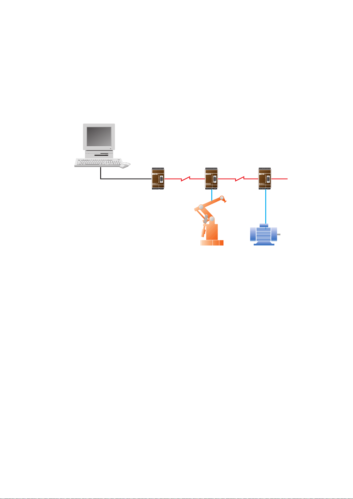
1. Intruduction
The MD-45 is used to convert between RS-422/485 and RS-232/V.24 signals.This device
is often used in multidrop applications connected to a PC or PLC.
In 2-wire half duplex applications (RS-485) the direction of the bus can be controlled
by data which means that the converter turns the bus depending on the data sent on the
bus. This makes it possible to use the unit with equipment that has no handshaking signals.The maximum transmission rate possible is 115.2 kbit/s.
123456789123456789
R+ R- T+ T- T+ T- R+ R-
CHANNEL 3
LD-01 DC
PWR
RD
TD
DCD2
DCD3
DCD4
CHANNEL 2 POWER
123456789123456789
CHANNEL 4
R+ R- T+ T- T+ T- R+ R-
CHANNEL 3
LD-01 DC
PWR
RD
TD
DCD2
DCD3
DCD4
CHANNEL 2 POWER
CHANNEL 4
123456789123456789
R+ R- T+ T- T+ T- R+ R-
CHANNEL 3
LD-01 DC
PWR
RD
TD
DCD2
DCD3
DCD4
CHANNEL 2 POWER
Page 4

4 6157-2213
2. Safety
General:
Before using this unit, read this manual completely and gather all information on
the unit. Make sure that you understand it fully. Check that your application does
not exceed the safe operating specifications for this unit.
Before installation,maintenance or modification work:
Prevent damage to internal electronics from electrostatic discharges (ESD)
by discharging your body to a grounding point (e.g. use of wrist strap).
Prevent access to hazardous voltages by disconnecting the unit from AC/DC
mains supply and all other electrical connections.
Installation:
This unit should only be installed by qualified personnel.
This unit should only be installed in a “restricted access area”, for example
a lockable cabinet where access is restricted to service personnel only.
This unit is intended for permanent connection to the AC/DC mains supply.
The power supply wiring must be sufficiently fused, and if necessary it must be
possible to disconnect manually from the AC/DC mains supply. Ensure compliance
to national installation regulations.
Unit with the rated voltage exceeding 42.4 V peak or 60 VDC, is defined as class I
equipment with a protective earthing conductor terminal.
Unit with the rated voltage up to 42.4 V peak or 60 VDC, is defined as class III
equipment and shall be separated from hazardous voltage by double or reinforced
insulation.
This unit uses convection cooling.To avoid obstructing the air flow around the
unit, follow the spacing recommendations (see under chapter Installation).
3. Approvals
Conformity with the Directive 73/23/EEC (Low Voltage Directive) has been assessed
by application of the standard EN 60 950.
Conformity with the Directive 89/339/EEC (Electromagnetic compatibility)
has been assessed by application of standards EN 61000-6-2 (industrial immunity)
and EN 61000-6-3 (residential emission).
!
!
!
Page 5

56157-2213
3.1 Declaration of conformity
Westermo Teleindustri AB
Declaration of conformity
The Westermo Teleindustri AB company declares that the listed products conforms to the Council
Directive 89/336/EEC, related to Electro Magnetic Compability and 72/23/EEC Low Voltage
Directive.
Type of equipment:
Model:
DIN-rail converter RS232-RS422/485
MD-45 AC 3157-0101, 3157-0110
MD-45 HV 3157-1101
MD-45 LV 3157-0001
Standards:
EMC: EN 61000-6-3/CISPR22(EN 55022): Class B
EN 61000-6-2/EN 61000-4-2
EN 61000-6-2/EN 61000-4-3
EN 61000-6-2/EN 61000-4-4
EN 61000-6-2/EN 61000-4-5
EN 61000-6-2/EN 61000-4-6
EN 61000-6-2/EN 61000-4-11
EN 61000-6-2/EN 61000-4-16
Safety: EN 60950
Reference: Installation manual MD-45 AC/HV,LV Art. Nr. 6157-2003
Hans Levin
Technical Manager
May 2003
Postadress/Postal address Tel. Telefax Postgiro Bankgiro Corp. identity number Registered office
S-640 40 Stora Sundby 016 - 42 80 00 016 ñ 42 80 01 52 72 79-4 5671-5550 556361-2604 Eskilstuna
Sweden Int +46 16 42 80 00 Int +46 16 42 80 01
Org.nr/ S‰te/
Page 6

6 6157-2213
4. Specifications
4.1 Interfaces
RS-485/422
Electrical specification RS-422/485
Data rate 1 200 – 115 200 bit/s
Connection 5-pos screw block
Connector size 0.2 – 2.5 mm
2
(AWG 24-12)
Circuit type TNV-1
RS-232
Electrical specification RS-232-C
Data rate 1 200 – 115 200 bit/s
Connection 9-pos D-sub, DCE
Circuit type SELV
4.2 Insulation between interfaces
Power
(MD-45 HV and AC)
to all other 3.0 kV RMS @ 50 Hz and 60 s duration
Power
(MD-45 LV)
to all other 1.0 kV RMS @ 50 Hz and 60 s duration
RS-232 to RS-485/422 1.0 kV RMS @ 50 Hz and 60 s duration
Model description MD-45 AC MD-45 LV MD-45 HV
Rated voltage 230 VAC 12–30 VAC 95–240 VAC
12–48 VDC 110–250 VDC
Operating voltage 207–253 VAC 10–45 VAC 85.5–264 VAC
9,6–60 VDC 88–300 VDC
Rated currant 22 mA 300 mA 25 mA @ 240 V,
50 mA @ 95 V
Rated frequency 48–62 Hz 48–62 Hz 48–62 Hz
Polarity PE, L and N Independent PE, L and N
Connection 3-pos screw block 2-pos screw block 3-pos screw block
Connector size 0.2 – 2.5 mm2(AWG 24-12)
Fuse To be externally fused
Power
Page 7

76157-2213
4.3 Climatic environment
Temperature, operating 5 to 55ºC
Temperature, storage and transportation –25 to 70ºC
Relative humidity, operating 5 to 95% (non-condensing)
Relative humidity, storage and transportation 5 to 95%
(condensation allowed outside packaging)
4.4 Mechanics
Dimension (W x H x D) 55 x 100 x 128 mm
Weight 0.5 kg AC, 0.25 kg HV and LV
Mounting 35 mm DIN-rail
Degree of protection IP 20 (IEC 529)
5. Maintenance
No maintenance is required, as long as the unit is used as intended within
the specified conditions.
Page 8

8 6157-2213
6. Installation
6.1 Mounting /Removal
Before mounting or removing the unit:
Prevent damage to internal electronics from electrostatic discharges (ESD)
by discharging your body to a grounding point (e.g. use of wrist strap).
Prevent access to hazardous voltages by disconnecting the unit from AC/DC
mains supply and all other electrical connections.
Mounting
This unit should be mounted on 35 mm DIN-rail which is horizontally mounted on a wall
or cabinet backplate.
This unit uses convection cooling. To avoid obstructing the air
flow around the unit, use the following spacing rules.
Minimum spacing 25 mm (1.0 inch) above/below and 10 mm
(0.4 inches) left/right the unit.
Snap on mounting, see figure.
Removal
Press down the black support at the back of the unit
using a screwdriver, see figure.
Min
10 mm
25 mm
25 mm
!
CLICK!
Page 9

96157-2213
6.2 Connections
Terminal connection
9-pos screw block
RS-232
Line connection
RS-422/485
Power
LED’s
Terminal connection
9-pos D-sub
RS-232
6.2.1 LED indicators
PWR Power Indication
RTS Request To Send modem signal
TD Transmitted Data: Displays data received from the local RS-232/422/485 port
RD Received Data: Displays data leaving the modem on the RS-232/422/485 port
CTS Clear To Send modem signal
Page 10

10 6157-2213
6.2.2 Power (MD-45 HV,AC)
3-pos screw terminal Description
L Line
N Neutral
Protective earth
6.2.3 Power (MD-45 LV)
2-position screw terminal Description
No. 1 –Voltage
No. 2 +Voltage
6.2.4 Line connection (RS-422/485)
5-position screw terminal Direction Description
No. 1 In A’ (R+)
No. 2 In B’ (R–)
No. 3 In/Out A (T+)
No. 4 In/Out B (T–)
No. 5 – Shield
6.2.5 Terminal connection (RS-232, DCE)
Screw terminal 9-pos D-sub Direction Description
7 2 Out Receive Data (RD)
8 3 In Transmit Data (TD)
1 & 9 5 - Signal ground (SG)
2 6 Out Data set ready (DSR)
6 7 In Request to send (RTS)
5 8 Out Clear to send (CTS)
5
4
3
2
1
9
8
7
6
Screw terminal 3 and 4 not used
N
L
1
2
123
4
5
5432167
8
9
Page 11

116157-2213
1
2
3
4
5
6
7
8
9
S2:1-4
S1:1-8
6.3 Configuration
6.3.1 DIP-switch settings
DIP-switches are accessible under the lid on top of the unit. DIP-switches are used to
configure the modem.
Warning!
Prevent damage to internal electronics from electrostatic discharges (ESD)
by discharging your body to a grounding point (e.g. use of wrist strap),
before the lid on top of the modem is removed.
Warning! Do not open connected equipment.
Prevent access to hazardous voltages by disconnecting the unit from AC/DC
mains supply and all other electrical connections.
NOTE! The change of DIP-switch settings are valid only after a power on.
If configured by any other method during normal operation, this new
configuration override the DIP-switch settings. However, after a new
power on the DIP-switch settings have precedence.
!
!
Page 12

12 6157-2213
ON
1234
Selection of bits
9
S1
10
S1
11
S1
12
S1
2/4-wire transmission
Termination with fail-safe *
2-wire
Terminated (4-wire)
S1
4-wire
S1
S2
ON
1234
Terminated (2-wire)
S2
ON
1234
S2
* The fail-safe function forces the signal state of
the receiver to OFF when the connected
transmitter is in tri-state (transmitter inactive).
The receiver located furthest away shall be
terminated.
Supervision table when selecting data bits
7 bits
8 bits
No parity
Parity
1 stop bit
2 stop bits
Number of bits 9 10 10 10 11 11 11 12
•
•
•
•
•
•
•
•
•
•
•
•
•
•
•
•
•
•
•
•
•
•
•
•
ON
12345678
ON
12345678
ON
12345678
ON
12345678
ON
12345678
ON
12345678
No termination
Selection of data rate
Data or RTS-control
1 200 780 µs
S1
2 400 410 µs
S1
4 800 220 µs
S1
9 600 130 µs
S1
19 200 48 µs
S1
38 400 34 µs
S1
57 600 22 µs
S1
115 200 11 µs
S1
Factory settings
ON
1234
S2
S1
S1: 8 not used
ON
12345678
ON
12345678
Data control
S1
RTS-control
S1
ON
12345678
ON
12345678
Transmitter
always active
S1
ON
12345678
ON
12345678
ON
12345678
ON
12345678
ON
12345678
ON
12345678
ON
12345678
ON
12345678
Data
rate
Turning
time
Page 13

136157-2213
V.11/RS-422
RS-485V.24/RS-232
3
4
A
B
TD LEDTD LED
3
TD
CTS
LED
S2:4
F1
0V
+5V
1
2
A'
B'
5
0V
RTS
CTS
RD
RD
LED
7
8
2
B
B
0V
SG
S1:6
Shield
DSR
6
+5V
5
S2:2
S2:1
S2:3
Power
supply
Insulated power supply
0V
+5V
B
+5V
Bus termination
0V
B
B
+5V
Bus termination
0V
B
B
A
A
A
RTS LED
MCU
7.0 Functional description
When the converter is set to data-control mode the transmitter is activated by data on
TD (RS-232).The time the transmitter stays active corresponds to one character-time
and turning time for the set data rate and number of bits. If there is more data on TD
before the turning time is ended the transmitter stays active for additional one character.
In RTS-control mode the transmitter is activated by the RTS-signal. In this mode the
switches for data rate and number of bits has no effect.The LED indicators is controlled
by the data signals.The active termination secures that the signal level at the receiver is
in off-state (>0.2 Volts) when there is no data transmission. Full duplex is only possible if
RS-422 is used.
7.1 Block diagram
Page 14

14 6157-2213
=Termination
Max 32 connections
Max 1 200 metres
Max 0.3 metre
=Termination
Max 32 connections
A
B
ABABAB
A’
B’
A
B
B’ A’ A’BBAB’A’BAAB’
N.B. R+/R–, T+/T– definitions are not standard, it can help to shift A and B
if the unit does not work.
7.2 Line connection
*) If shielded cable is used, connect the shield only at one end to avoid ground currents.
4-wire
MD-45
RS-422/485
equipment
RS-422/485
equipment
Transmitter/
Receiver
Transmitter/
Receiver
Twisted pairs
Twisted pairs
Receiver
Transmitter
Transmitter
Receiver
A’
B’
A
B
A
B
A’
B’
Shield *) Shield *)
A/A’ A/A’
B/B’ B/B’
1
2
3
4
5
3
4
5
MD-45
2-wire
7.3 Hints
RS-422/485 was designed for multidrop applications. When a system is installed it should
form a bus structure (see diagrams). Star shaped networks should never be created,
there are other Westermo products designed to work in star net applications. To get a
correct installation according to the RS-422/485 specification it´s very important that the
line is terminated at the correct points. The recommendation is to terminate the receiver on the master unit and the final bus slave unit. See diagrams for details of how this is
done with RS-485 (2-wire) and RS-422 (4-wire).
The line transmitter used in the MD-45 is activated by data received on the RS-232
interface, unlike conventional converters that rely on a control signal (e.g. RTS).
If any problems do occur on set up of the MD-45, the LED’s will be helpful.
• PWR: The unit has power.
• RD: Data received on the RS-422/485 interface.
• CTS: Follows RTS.
• RTS: Status of RTS from the RS-232 interface.
• TD: Data received on RS-232 interface.
Page 15

156157-2213
OWN COMMENTS
.....................................................................................................................................................................................................................
.....................................................................................................................................................................................................................
.....................................................................................................................................................................................................................
.....................................................................................................................................................................................................................
.....................................................................................................................................................................................................................
.....................................................................................................................................................................................................................
.....................................................................................................................................................................................................................
.....................................................................................................................................................................................................................
.....................................................................................................................................................................................................................
.....................................................................................................................................................................................................................
.....................................................................................................................................................................................................................
.....................................................................................................................................................................................................................
.....................................................................................................................................................................................................................
.....................................................................................................................................................................................................................
.....................................................................................................................................................................................................................
Page 16

PWR RD1 TD1 RD2 TD2 RD3 TD3 RD4 TD4
RD TD DCD RTS CTS DTR RD TC
ACCESS XX-00
PWR RD1 TD1 RD2 TD2 RD3 TD3 RD4 TD4
RD TD DCD RTS CTS DTR RD TC
ACCESS XX-00
PWR RD1 TD1 RD2 TD2 RD3 TD3 RD4 TD4
RD TD DCD RTS CTS DTRR D TC
ACCESS XX-00
6157-2213 03.06 Mälartryck AB, Eskilstuna, Sweden
Application examples
Westermo Web site: www.westermo.us
Westermo US
Phone 877-268-3700 Fax 877-268-9700
Web site: www.westermo.us
 Loading...