

Page 1
Strömslingeomvandlare
Current loop converter
Stromschleifenwandler
INSTALLATIONSANVISNING
INSTALLATION MANUAL
INSTALLATIONS ANLEITUNG
6151-2002
www.westermo.se
MD-21 AC
MD-21DC
©
Westermo Teleindustri AB • 1999 REV. A
Galavanic
Isolation
Transient
Protection
CE
Approved
Page 2

8 6151-2002
Specifications
Transmission Asynchronous, full/half duplex or simplex
Interface 1 EIA RS-232-C/CCITT V.24
9-position D-sub female / screw-terminal
Interface 2 20mA current loop, selectable active or passive
Data rate Up to 19200 bit/s
Indicators Power, RD, TD
Isolation Galvanic isolation with opto-coupler
(data transmission) and transformer (supply)
Isolation voltage 1500V
Overvoltage protection Mains: Breakdown voltage 430V at 230V AC
and 220V at 115V AC*
Interface 2: Breakdown voltage transmitter and
receiver 37V. Surge capacity 0.6 kW for 1 ms
Power supply** 115V*/230V AC +15/-10% 48-62Hz
Fuse 100mA fast 5x20mm
Power consumption Max 4VA at 115V and 230V
Temperature range 5-50° C, ambient temperature
Humidity 0-95% RH, non-condensing
Dimensions 55x100x128 mm
Weight 0.4 kg
Mounting On a 35mm DIN-rail
** For other power supply voltages contact Westermo.
* Only MD-21 115V
Page 3
96151-2002
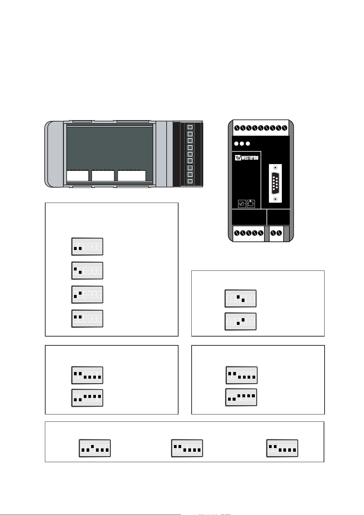
Settings MD-21
The MD-21 can through different switch settings be adapted to a variety of running
conditions. To set the switches, open the lid on the top of the plastic case.
WARNING! DO NOT OPEN CONNECTED UNIT
123456789
S4:1-6
S1:1-6S3:1-6
Inverted Transmitter/Receiver
Receiver active/passive
Factory settings
Transmitter
Normal Normal
Normal
Inverted
Inverted
Inverted
Normal
Inverted
Receiver
S1
S1
S1
S1
Passive
S3
Active
S3
S3
Transmitter active/passive
Passive
S4
Active
S4
S4
ON
123456
ON
123456
ON
123456
ON
123456
ON
123456
ON
123456
ON
123456
ON
123456
ON
123456
ON
123456
CTS-control
Always high
S1
S1
RTS
S1
ON
123456
ON
123456
ON
123456
S1: 5-6 not used
TD RDPWR RTS CTS DCD DSRDTR SG
105 106 109 108 107 102
103 104
V24/RS-232-C
CONNECTION
MD-21DC
V24/RS-232-C
CURRENT LOOP
CONVERTER
LINE CONNECTION
R+ R- T+ T-
12345
POWER
12-36V DC
-+
Page 4

Receiver 1 R+
Receiver 2 RTransmitter 3 T+
Transmitter 4 T-
5 Shield
10 6151-2002
N 115V*/230V
L AC power
PE/Protective Earth
I 3 8 103 TD/Transmitted Data
O 2 7 104 RD/Received Data
I 7 6 105 RTS/Request To Send
O 8 5 106 CTS/Clear To Send
O 6 2 107 DSR/Data Set Ready
– 5 9 & 1 102 SG/Signal Ground
O 1 4 109 DCD/Data Carrier Detect
NC 4 3
Description
Connections MD-21
Line connection
(5-Position screw-terminal)
MD-21
20mA current loop equipment
Transmitter
Receiver
1
2
3
4
5
R+
R-
T+
T-
T+
T-
R+
R-
Receiver
Trans-
mitter
Shield 1)
Direction
No.
Description
Power connection (AC)
(3-position screw-terminal)
Line connection MD-21
Terminal connection (DCE)
(RS-232-C/V.24, 9-position D-sub female or screw-terminal)
I=input O=output. MD-21 is a DCE (Data Communication Equipment).
NC=not connected.
Screw
no.
Power
Supply
Direction 1)
Pin
no.
Screw
no.
CCITT V.24
Circuit no.
1) If shielded cable is used, connect the shield only at one end to avoid ground currents.
* MD-21 115V
Page 5

116151-2002
Transmission rate bit/s
Transmission range (interface 2)
Switch settings
According to MD-21
Connections
According to MD-21, except power supply
MD-21 DC
Specifications
Power supply 12-36V DC
Power consumption Max 3W
Isolation 500V
Fuse F1 1.6A fast 5x20 mm
All other specifications according to MD-21
Cable
42pF/m 600 1200 2400 4800 9600 19200
0.3 mm
2
6000 m 5000 m 4000 m 3000 m 500 m 200 m
1 – Voltage
2 + Voltage
Screw
no.
Power Supply
Page 6

RD
▼
TD
▼
TD
▼
RD
▼
Connecting the MD-21 in a 20mA current loop
12 6151-2002
3
4
34
RD
12
1
2
▼
▼
▼
▼
▼
▼
▼
34 12
▼
▼
▼
▼
TD
▼
TD
▼
TD
Master
S1: 3 on
S3: 1, 2 on
S4: 3–6 on
S1: 3 on
S3: 1, 2 on
S4: 1, 2 on
Slaves
▼
RD
▼
RD
▼
3
4
34 12
1
2
▼
▼
▼
▼
▼
34 12
▼
▼
▼
▼
TD
Master
S1: 3 on
S3: 3–6 on
S4: 3–6 on
S1: 3 on
S3: 1, 2 on
S4: 1, 2 on
Slaves
▼
RD
▼
Functional description
When transmitting from the master, RD and TD flash. RD flashes on both slaves.
When transmitting from a slave both RD and TD flash and on the other slaves and
the master RD flashes.
Functional description
When transmitting from a slave the TD led flashes only on that unit. The RD led flashes
only on the master modem.
When transmitting from the master, TD flash. RD flashes on both slaves.
Half duplex transmission
Full duplex transmission
Page 7

Hints
The 20mA current loop interface, or TTY as it is sometimes known, is a
popular industrial communications standard. The system relies on a current generator running on both the transmit and receive circuits. On each
circuit it is important to have only one current generator supplying current into that circuit. For this reason the MD-21 can have its current generators set to be either active or passive. It is important to check the state
of all attached equipment to ensure correct setting on the MD-21. A maximum of 6 devices can be connected in a loop.
The RS-232 interface is configured as DCE (Data Communication
Equipment). Most printers, PC’s and terminals are set as DTE (Data
Terminal Equipment). Some recomendation of cable configurations are
given below.
If any problems do occur on set up of the MD-21, the LED’s will be helpful.
- PWR: The unit has power.
- RD: Data received on line interface.
- TD: Data received on RS-232 interface.
A good way to check the MD-21 is to carry out a loop back test. Ensure
that either the transmitter or receiver are set to active, but not both
active or both passive. Connect T+ to R+ and T- to R-. Connect the
RS-232 interface to a terminal. When keys are pressed on the terminal
you should receive the echo on screen. The TD & RD lights will both
flicker simultaneously as you press the keys.
136151-2002
1
2
3
4
5
6
7
8
9
10
11
12
13
14
15
16
17
18
19
20
21
22
23
24
25
1
2
3
4
5
6
7
8
9
1
2
3
4
5
6
7
8
9
10
11
12
13
14
15
16
17
18
19
20
21
22
23
24
25
1
2
3
4
5
6
7
8
9
1
2
3
4
5
6
7
8
9
1
2
3
4
5
6
7
8
9
DTE MD-21 D-sub
DCE MD-21 D-sub
9-pol. PC MD-21 D-sub
Page 8

1) 0 Ω resistors R1, R48-R50 are normally not mounted.
2) Metal housing on D-sub is connected to PE if R is mounted.
R = R3 on the DC-mod and R1 on AC-mod.
Block diagram
V.24/RS-232
TD
DSR
OVB
DCD
CTS
RTS
RD
SG
+12V
0V
-12V
D-sub housing
PE
Power
supply
Insulated power supply
Line
T+
S4
20mA
PWR
F1
=1
=1
+24VB
+24VB
20mA
S3
3
4
1
2
5
3
6
1
8
74
3
S1
2
5
1,2)
R
R47
6
5
2
4
1
3
6
5
2
4
1
3
1
2
+
+
S1
T-
R+
+12V
+12V
+12V
TD
R-
Shield
PE
0VB
S1
RD
R48
R50
R49
1)
1)
OVB
+24VB
6151-2002 01.99 TunaTryck AB, Eskilstuna, Sweden
Westermo Teleindustri AB • S-640 40 Stora Sundby, Sweden
Phone +46 16 612 00 Fax +46 16 611 80
E-mail: info@westermo.se • Westermo Web site: www.westermo.se
Westermo Teleindustri AB have distributors in several countries,
contact us for further information.
Westermo Data Communications GmbH
Bruchsaler Straße 18, 68753 Waghäusel
Tel.: +49(0)7254-95400-0 • Fax.:+49(0)7254-95400-9
E-Mail: westermo.germany@t-online.de
Westermo Data Communications Ltd
Solent Business Centre • Millbrook Road West
Millbrook, Southampton • SO15 0HW
Phone: +44(0)1703-704 611 • Fax.:+44(0)1703 702 682
E-Mail: sales@westermo.co.uk
Subsidiaries
 Loading...