

Page 1
Omvandlare, optisk fiber
RS-422/485/V.11
Converter, fibre optic
RS-422/485/V.11
Glasfaser Wandler
RS-422/485/V.11
INSTALLATIONSANVISNING
INSTALLATION MANUAL
INSTALLATIONS ANLEITUNG
6067-2001
www.westermo.se
MA-67
©
Westermo Teleindustri AB • 1998 • REV. A
Galvanic
Isolation
Transient
Protection
Balanced
TransmissionCEApproved
Page 2

8 6067-2001
Specifications MA-67
Transmission Asynchronous, full/half duplex or simplex
Interface 1 EIA RS-422/RS-485
CCITT V.11, 5-position screw-terminal
Interface 2 ST-connectors, see table of power budget
Surge protection Interface 1: transient protection,
flashover voltage for receiver and transmitter 7V.
Dissipation capability 0.6 kW for 1 ms.
Insulation 1500V rms isolation withstand voltage between
communication line and mains.
Power supply +20V DC ±25% (via PS-02)
Fuse 500 mA fast 5x20
Data rate 2.4 kbit/s up to 1,5 Mbit/s
Indicators Power, TD, RD
Power consumption Max 80 mA at 20V DC
Temperature range 5-50°C, ambient temperature
Humidity 0-95% RH without condesation
Dimension 100x100 mm
Weight 0.4 kg
Mounting I 19” rack RV-01, possible to mount
16 MA-67 in a RV-01
Page 3
96067-2001
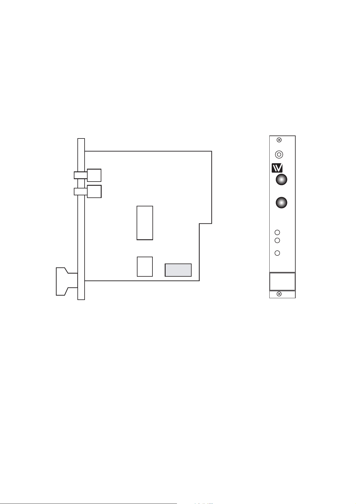
S1
F1
S2
TX
RX
S1 Selection of 2-or 4-wire
Selection of turning time/transmission rate
Selection of bits
S2 Selection of termination
Selection of transmitted power
F1 Fuse
MA-67
RX
RD
TD
PWR
TX
Description MA-67
The MA-67 allows RS-422/485 point to point communication over fibre optic multi
mode or single mode cables, at data rates up to 1.5 Mbit/s. Transmission distances up to
25 km (single mode) can be reached.
The MA-67 is designed to be mounted in the Westermo RV-01 and RV-01A racks.
Up to 16 units can be mounted in one rack.
Three LED’s are provided to indicate TX, RX and power. The fibre optic connection
are mounted on the front of the panel and are of the ST type. All other connections are
via the mother board of the RV-01 rack.
Page 4

10 6067-2001
Selection of 2- or 4-wire
S1 4-wire
Turning
time
Transmission
rate
ON
123456789
S1 2-wire
ON
123456789
Selection of bits
S1 9
ON
123456789
S1 10
ON
123456789
S1 11
ON
123456789
See 2)
2) For synchronous and other asynchronous protocol.
S1: 2-3 not used
ON
123456789
Turning time/
Transmission rate
ON
123456789
S1 0.4 ms 2400 bit/s
ON
123456789
S1 0.2 ms 4800 bit/s
ON
123456789
S1 0.1 ms 9600 bit/s
ON
123456789
S1 75 µs 14400 bit/s
ON
123456789
S1 50 µs 19200 bit/s
ON
123456789
S1 37 µs 28800 bit/s
ON
123456789
S1 25 µs 38400 bit/s
ON
123456789
S1 16 µs 62500 bit/s
ON
123456789
S1 11 µs 93750 bit/s
ON
123456789
S1 9 µs 115.2 kbit/s
ON
123456789
S1 6 µs 187.5 kbit/s
ON
123456789
S1 3 µs 375 kbit/s
ON
123456789
S1 2 µs 500 kbit/s
ON
123456789
S1 1 µs 1-1.5 Mbit/s
••• •
•• • •
•••
••• •
•••
•••
10 10 10 11 11 119
Supervision table when selecting data bits
7 bits
8 bits
No parity
Parity
1 stop bit
2 stop bits
Number of bits
Factory settings
S1
ON
123456789
S2
ON
12345
Page 5

116067-2001
Termination with fail-safe 1)
S2
1) The fail-safe function forces the signal state of the
receiver to OFF when the connected transmitter is in
tri-state transmitter inactive). The receiver located
furthest away shall be terminated.
ON
12345
Termination (2-wire)
S2
ON
12345
Termination (4-wire)
S2
ON
12345
No termination
Transmitted power
S2
ON
12345
Low
S2
ON
12345
High
Typical attenuation
in connectors
0.2-0.4 dB
Typical attenuation
in splice
Fusion 0.1 dB
Mechanical 0.2 dB
Power budget
Fibre 820 nm 1300 nm Single mode 820 nm 1300 nm Single mode
Min. values Min. value Min. value Typ. value Typ. value Typ. value
50/125 µm 10.7 dB
62,5/125 µm 14.5 dB 11.6 dB 18.6 dB 15.1 dB
100/140 µm 20 dB
9/125 µm 6.3 dB 12.3 dB
Fibre Attenuation Attenuation Attenuation
at 820 nm at 1300 nm at single mode (1300 nm)
50/125 µm 3.0 dB/km 1.0 dB/km
62,5/125 µm 3.5 dB/km 1.2 dB/km
100/140 µm 4.0 dB/km
9/125 µm 0.5 dB/km
Attenuation in fibre cable
The values below can differ depending on quality and manufacturer of the fibre-optic
cable.
”Min. value” states the minimum guaranteed power budget. Experience shows however that the
typical value is in the range of the indicated ”Typ. value”.
Page 6

12 6067-2001
Line connection
TX
RX
TX
RX
Shield 1)
Equipment with
RS-422/V.11
MA-66, MA-67,
LD-63, MD-62/63
MA-66, MA-67,
LD-63, MD-62/63
= Termination
MA-67
T+
T–
R+
R–
1
2
3
4
5
R– R+ T– T+
R+
R–
T+
T–
TX
RX
TX
RX
Shield 1)
Equipment with
RS-485
= Termination
1) If shielded wire is used, connect shield only one end to avoid ground loop currents.
MA-67
3
4
5
T–/R– T+/R+
T+/R+
T–R–
T+/R+
T–/R–
Direction Connection CCITT V.24
No. Description
Receiver 1 A’ (R+)
Receiver 2 B’ (R–)
Transmitter 3 A (T+)
Transmitter 4 B (T–)
5 Shield
Connections MA-67
Line connection
(5-position screw terminal)
Rear wiew of
RV-01 with
MA-67 mounted.
5 position screw
terminal.
Connection of
RS-422/485
Page 7

136067-2001
Hints
The MA-67 like other Westermo products MA-42, MD-42, MD-63, LD-64, MA-44,
MD-44, MM-42, MA-49, MA-47, RA-48, RD-48 and LD-63 uses the RS-422/485
interfaces.
RS-422/485 were designed for multidrop applications. When a system is installed it
should form a bus structure. Star shaped networks should never be created, there are
other Westermo products designed to work in star net applications. To correctly install,
an RS-422/485 network should be terminated at the correct points.
The recommendation is to terminate the receiver on the first unit and the final bus unit.
See diagrams under the headline ”Line connection” for details of how this is done with
RS-485 (2 wire) and RS-422 (4 wire).
If any problems do occur on set up of the MA-67, the LEDs will be helpful.
- PWR: The unit has power.
- RD: Data received on the opto interface.
- TD: Data received on the RS-422/485 interface.
Page 8

6067-2001 11.98 TunaTryck AB, Eskilstuna, Sweden
Westermo Teleindustri AB • S-640 40 Stora Sundby, Sweden
Phone +46 16 612 00 Fax +46 16 611 80
E-mail: info@westermo.se • Westermo Web site: www.westermo.se
Westermo Teleindustri AB have distributors in several countries,
contact us for further information.
Westermo Data Communications GmbH
Bruchsaler Straße 18, 68753 Waghäusel
Tel.: +49(0)7254-95400-0 • Fax.:+49(0)7254-95400-9
E-Mail: westermo.germany@t-online.de
Westermo Data Communications Ltd
Solent Business Centre • Millbrook Road West
Millbrook, Southampton • SO15 0HW
Phone: +44(0)1703-704 611 • Fax.:+44(0)1703 702 682
E-Mail: sales@westermo.co.uk
Subsidiaries
Block diagram
+5V
TX
RX
S2:1
3
4
1
2
S2:2
S2:5
S1:1
S2:3
S2:4
R1 1)
Direction
control
High
Low
Insulated power supply
0V
+5V
0V
PE
0V
+5V
Fuse
0V
1) Jumper R1 normally not mounted
V.11/RS-422
RS-485
Power
supply
 Loading...