

Page 1
Omvandlare, optisk fiber
- RS-232/V.24
Converter, fibre optic
- RS-232/V.24
Glasfaser Wandler
RS-232/V.24
INSTALLATIONSANVISNING
INSTALLATION MANUAL
INSTALLATIONS ANLEITUNG
6066-2001
www.westermo.se
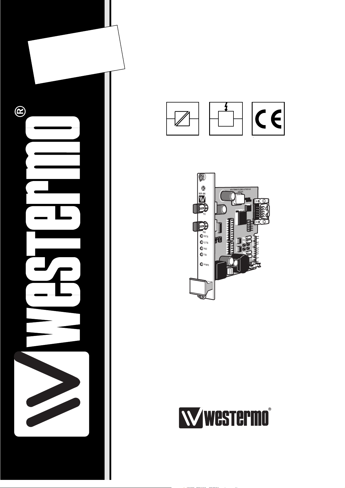
MA-66
©
Westermo Teleindustri AB • 1998 • REV. A
Galvanic
Isolation
Transient
Protection
CE
Approved
Page 2

8 6066-2001
Specifications MA-66
Transmission Asynchronous, full/half duplex or simplex
Interface 1 EIA RS-232/CCITT V.24 9 pole D-sub connector
female or 9 pole screw block
Interface 2 ST-connectors, see table of power budget
Data rate up to 115.2 kbit/s
Isolation 1500V rms
Indicators Power, TD, RD, CTS, RTS
Power supply +20V DC ±25% (Via PS-02)
Power consumption Max 80 mA at 20V DC
Fuse 500 mA fast 5x20 mm
Temperature range 5-50°C ambient temperature
Humidity 0-95% RH without condensation
Dimension 100x100 mm
Weight 0.4 kg
Mounting In racks RV-01, several models available.
Possible to assemble 16 pcs MA-66 in an RV-01
Description MA-66
The MA-66 allows RS-232 point to point communication over fibre optic multi mode or
single mode cables, at data rates up to 115.2 Kbit/s. Transmission distances up to 25 km
(single mode) can be reached.
The MA-66 is designed to be mounted in the Westermo RV-01 and RV-01A racks.
Up to 16 units can be mounted in one rack.
Five LED’s are provided to indicate TX, RX, RTS, CTS and power. The fibre optic
connections are mounted on the front of the panel and are of the ST type. A 9 way
D-sub at the rear of the card provides the connectivity for the RS-232. All other
connections are via the mother board of the RV-01 rack.
Page 3
96066-2001
Status signal
Factory settings
S1 Enabled
ON
123456789
S1 Disabled
ON
123456789
S1
ON
123456789
S2
ON
12345
S2
ON
12345
Switch S1: 2-9 not used
Transmitted power
Low
S2
ON
12345
High
Switch S2: 1-4 not used
Switch settings MA-66
The MA-66 can, through switch settings, be set in to several modes.
MA-66
RX
RTS
CTS
RD
TD
PWR
TX
19
5
6
Page 4

10 6066-2001
Attenuation in fibre cable
The values below can differ depending on quality and manufacturer
of the fibre-optic cable.
Fibre Attenuation Attenuation Attenuation
at 820 nm at 1300 nm at single mode (1300 nm)
50/125 µm 3.0 dB/km 1.0 dB/km
62.5/125 µm 3.5 dB/km 1.2 dB/km
100/140 µm 4.0 dB/km
9/125 µm 0.5 dB/km
Typical attenuation
in connectors
0.2-0.4 dB
Typical attenuation
in splice
Fusion 0.1 dB
Mechanical 0.2 dB
Fibre 820 nm 1300 nm Single mode
Min. values Min. value Min. value
50/125 µm 10.7 dB
62.5/125 µm 14.5 dB 11.6 dB
100/140 µm 20 dB
9/125 µm 6.3 dB
Fibre 820 nm 1300 nm Single mode
Typ. values Typ. value Typ. value
50/125 µm
62.5/125 µm 18.6 dB 15.1 dB
100/140 µm
9/125 µm 12.3 dB
Power budget
Page 5

116066-2001
Direction 1) Pin CCITT V.24 Description
no Circuit no
I 3 103 TD/Transmitted Data
O 2 104 RD/Received Data
I 7 105 RTS/Request To Send
O 8 106 CTS/Clear To Send
– 5 102 SG/Signal Ground
Connections MA-66
Terminal connection (DCE)
(RS-232-C/V.24, 9 pole female D-sub connector)
Fibre optic connection
1) I = Input O = Output on MA-66
MA-66
RX
TX
RX
TX
MA-66
Page 6

12 6066-2001
Hints
If any problems occur upon set-up of the MA-66, the following notes may be helpful.
1. Power up the MA-66 and check that
the PWR LED is lit.
2. Check the cable between your RS-232
interface and the RS-232 connection on
the MA-66. The RS-232 interface on the
MA-66 is configured as DCE (Data
Communication Equipment). Most printers, PCs and terminals are set as DTE
(Data Terminal Equipment). See the
3 suggestions of cable configurations on
pages 13.
How to check whether the equipment is
DTE or DCE:
• Power up the unknown equipment and
ensure that nothing is plugged into the
RS-232 interface. Using a multi-meter,
first measure the voltage on pin 2 of the
connector (male or female) with reference to ground on pin 7 (25 pole
connector) or on pin 5 (9 pole connector, PC standard). Then measure the
voltage on pin 3 in the same way. The
pin with the most negative voltage will
be the output pin and will identify the
device as DCE or DTE.
9 pole connector,PC standard
• If the most negative voltage is on pin 3:
the device is DTE.
• If the most negative voltage is on pin 2:
the device is DCE.
25 pole connector, PC standard
• If the most negative voltage is on pin 2:
the device is DTE.
• If the most negative voltage is on pin 3:
the device is DCE.
3. The RS-232 cable is correct but it still
does not work. The LEDs may be helpful.
• PWR: The unit has power
• RD: Data received from fibre
interface
• TD: Data received from RS-232
interface
• RTS: RTS from RS-232 side
• CTS: RTS from the line side
4. Test each individual modem. All switches
in OFF state. Make sure that the mainspower socket is disconnected when the
modem lid is off.
A. Equipment required: a terminal or a PC
with terminal program, an RS-232 cable
according to point 2, and a fibre cable.
B. Connect a cable between the modem
and terminal, or PC with a terminal
program. Connect the fibre cable between RX and TX.
C. Press any key on the keyboard. During
keystrokes, the TD and RD LED’s
should flash on the modem, simultaneously, the characters will be echoed on
the monitor.
D. If the fibre cable is removed from one
port only, the TD LED will flash when
a key is pressed, but no characters will
appear on the screen.
Repeat the same test with the second
modem.
5. Testing the modems together.
A. Leave the last tested modem in place,
connected to the terminal or the PC
(modem A).
B. Connect two fibre cables between the
modems RX (modem A) – TX (modem
B) and vice versa.
C. Connect pins 2 and 3 of the RS-232
interface on modem B (top screw terminal 7, 8).
D. Press any key on the keyboard. During
keystrokes, the TD and RD LED’s
should flash on the modem, simultaneously, the characters will be echoed on
the monitor.
Page 7

136066-2001
1
MA-66 D conn.
1
DTE MA-66 D conn.DCE
MA-66 D conn.9 pole (PC)
2
3
4
5
6
7
8
9
1
2
3
4
5
6
7
8
9
20
21
25
2
3
4
5
6
7
8
9
1
2
3
4
5
6
7
8
9
1
2
3
4
5
6
7
8
9
1
2
3
4
5
6
7
8
9
20
21
25
Page 8

6066-2001 11.98 TunaTryck AB, Eskilstuna, Sweden
Westermo Teleindustri AB • S-640 40 Stora Sundby, Sweden
Phone +46 16 612 00 Fax +46 16 611 80
E-mail: info@westermo.se • Westermo Web site: www.westermo.se
Westermo Teleindustri AB have distributors in several countries,
contact us for further information.
Westermo Data Communications GmbH
Bruchsaler Straße 18, 68753 Waghäusel
Tel.: +49(0)7254-95400-0 • Fax.:+49(0)7254-95400-9
E-Mail: westermo.germany@t-online.de
Westermo Data Communications Ltd
Solent Business Centre • Millbrook Road West
Millbrook, Southampton • SO15 0HW
Phone: +44(0)1703-704 611 • Fax.:+44(0)1703 702 682
E-Mail: sales@westermo.co.uk
Subsidiaries
Block diagram
RS-232-C/V.24
RTS
S1:1
7
3
2
8
5
0V
PE
5VA
0V
5V B
0V
1) Jumper R1 normally not mounted
R1 1)
High
Low
S2:5
TX
RX
TD
RD
CTS
SG
Isolated
power supply
Modu-
lator
De-
Modu-
lator
Power
supply
 Loading...