

Page 1
Omvandlare, RS-232 – RS-422/485
Converter, RS-232 – RS-422/485
RS-232 – RS-422/485 Wandler
INSTALLATIONSANVISNING
INSTALLATION MANUAL
INSTALLATIONS ANLEITUNG
6047-2002
www.westermo.se
©
Westermo Teleindustri AB • 1999 • REV. A
Galvanic
Isolation
Transient
Protection
Balanced
TransmissionCEApproved
MA-47
Page 2

96047-2002
Specifications MA-47
Transmission: Asynchronous, full/half duplex or simplex
Interface 1: EIA RS-232-C/CCITT V.24/V.28
25-position D-sub female, DCE
Interface 2: EIA RS-422/RS-485/CCITT V.11
Data rate: Up to 38.4 Kbit/s
Indicators: Power, RD, DCD, CTS, RTS, TD
Insulation: Galvanic insulation with opto-coupler
(data transmission) and transformer (supply)
Insulation voltage: 1500V
Overvoltage protection: Breakdown voltage transmitter and receiver 7V.
Surge capacity 0.6 kW for 1ms.
Power supply: External through PS-02 mounted in rack RV-01.
±20VDC ±20%
Fuse: 2 pcs 100 mA fast 5x20mm
Power consumption: +20V 70mA, –20V 45mA
Temperature range: 5–50°C, ambient temperature
Humidity: 0–95% RH, non-condensing
Dimensions: 100x100mm
Weight: 0.1 kg
Mounting: To be mounted in rack RV-01, takes one card slot.
Page 3
10 6047-20021010
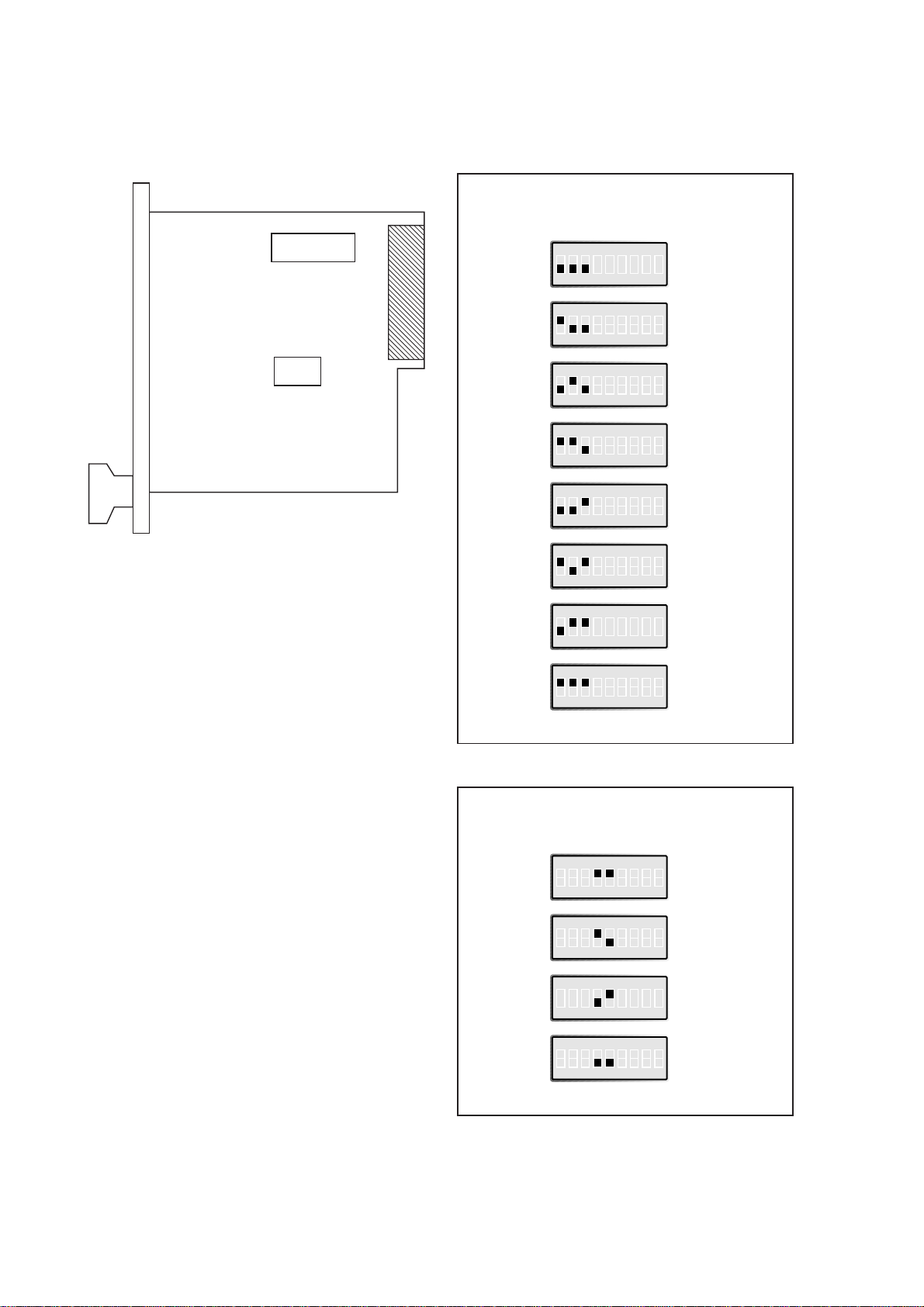
Selection of data rate
Selection of bits
ON
123456789
ON
123456789
ON
123456789
ON
123456789
ON
123456789
ON
123456789
ON
123456789
ON
123456789
ON
123456789
ON
123456789
ON
123456789
ON
123456789
S2 Selection of data rate
Selection of 2- or 4-wire transmission
Selection of no, of data bits
(see table below)
S3 Selection of termination
and fail-safe)
S2 300 bit/s
S2 600 bit/s
S2 1200 bit/s
S2 2400 bit/s
S2 4800 bit/s
S2 9600 bit/s
S2 19200 bit/s
S2 38400 bit/s
S2 9
S2 10
S2 11
S2 12
Switch settings
The MA-47 can through different switch settings be adapted to a variety of running conditions.
S2
1 – 9
S3
1 – 4
ON
OFF
ON
OFF
Page 4
116047-2002 11
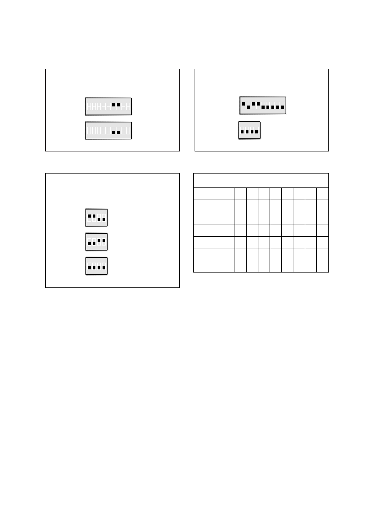
2/4-wire transmission
ON
123456789
ON
123456789
Factory settings
S2
S3
ON
123456789
Termination
with fail-safe
ON
1234
ON
1234
ON
1234
ON
1234
The fail-safe function forces the signal state of the
receiver to OFF when the connected transmitter is in
tri-state (transmitter inactive). The receiver located
furthest away shall be terminated.
S1: 8-9 not in use
Supervision table when selecting data bits
7 bits ●●● ●
8 bits ●●●●
No parity ●● ● ●
Parity ●●●●
1 stop bit ●●● ●
2 stop bits ●●●●
Number of bits 9 10 10 10 11 11 11 12
S2 2-wire
S2 4-wire
S3 Terminated (4-wire)
S3 Terminated (2-wire)
S3 No termination
Page 5

12 6047-2002
Direction Pin CCIT V.11
no. Description
Receiver 1 A’ (R+)
Receiver 2 B’ (R-)
Transmitter 3 A (T+)
Transmitter 4 B (T-)
Shield
Connections
Line connection
(5-Position screw-terminal)
Direction Connection CCITT V.24 Signal name
Code
I 2 103 TD/Transmitted Data
O 3 104 RD/Received Data
I 4 105 R TS/Request T o Send
O 5 106 CTS/Clear To Send
O 6 107 DSR/Data Set Ready
– 7 102 SG/Signal Ground
O 8 109 DCD/Data Carrier Detect
I 20 108/2 DTR/Data T erminal Ready
I = Input O = Output on MA-47
Terminal connection (DCE)
(RS-232-C/V.24/V.28, 25-Polig D-sub, female)
Line connection
1) If shielded cable is used, connect the shield only at one end to avoid ground currents.
Look right for a section of rack RV-01 with
one MA-47 mounted.
Terminal connection to a 25-position D-sub(female) connector on MA-47.
Line connection to a 5-position detachable screw-terminal, which is mounted on the
male connector located at the rear of RV-01.
The definations R+/R–, T+/T– can be various
between different manufactures.
12345
1
14
13
25
1
2
3
4
5
2-wire4-wire
Transmitter/
Receiver
Shield
MA-47
1)
3
A/A’
4
B/B’
5
Receiver
Transmitter
Shield
MA-47
1
2
3
4
1)
5
RS-422
Twisted pairs
A’
B’
A
B
equipment
A
Transmitter
B
A’
Receiver
B’
Twisted pairs
A/A’
B/B’
RS-485
equipment
Transmitter/
Receiver
Page 6
136047-2002
Transmission range (interface 2)
Use twisted pair cable. Max transmission range 1200 m.
(cable specifications 0.3mm
2
and capacitance 42pF/m).
The transmission range will increase if a cable with lower capacitance and larger
diameter is used.
Use shielded cable in heavy industrial environments.
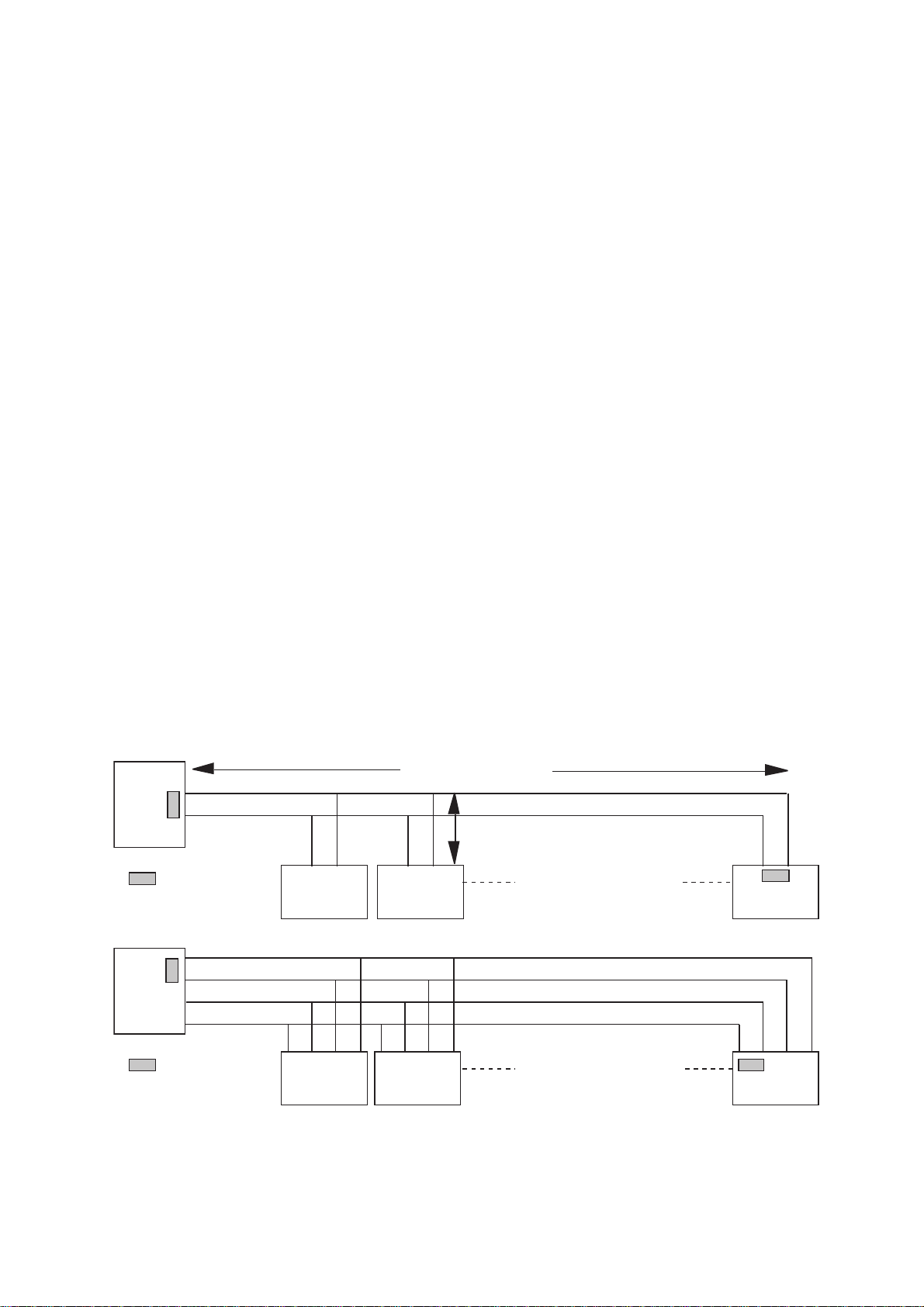
Hints
The MA-47 uses the RS-422/485 interface. RS-422/485 was designed for multidrop applications. When a system is installed it should form a bus structure (see diagrams). Star
shaped networks should never be created, there are other Westermo products designed
to work in star net applications. To install correctly, an RS-422/485 network should be
terminated at the correct points. The recommendation is to terminate the receiver on
the master unit and the final bus slave unit. See diagrams for details of how this is done
with RS-485 (2 wire) and RS-422 (4 wire).
The line transmitter used in the MA-47 is activated by data received on the RS-232
interface, unlike conventional converters that rely on a control signal (e.g. RTS).
If any problems do occur on set up of the MA-47, the LED’s will be helpful.
• PWR: The unit has power.
• RD: Data received on the RS-422/485 interface.
• DCD: Follows RD in two wire operation. Always active for four wire.
• CTS: Follows RTS
• RTS: Status of RTS from the RS-232 interface
• TD: Data received on RS-232 interface
=Termination
Max 32 connections
Max 1200 metres
Max 0.3 metre
=Termination
Max 32 connections
A
B
ABABAB
A’
B’
A
B
B’ A’ A’BBA B’ A’ B AAB’
N.B. R+/R–, T+/T– definitations are not standard, it can help to shift A and B
if the unit does not work.
Page 7
V.24/RS-232
6047-2002 08.99 Mälartryck AB, Eskilstuna, Sweden
Westermo Teleindustri AB • S-640 40 Stora Sundby, Sweden
Phone +46 16 612 00 Fax +46 16 611 80
E-mail: info@westermo.se • Westermo Web site: www.westermo.se
Westermo Teleindustri AB have distributors in several countries,
contact us for further information.
Westermo Data Communications GmbH
Bruchsaler Straße 18, 68753 Waghäusel
Tel.: +49(0)7254-95400-0 • Fax.:+49(0)7254-95400-9
E-Mail: westermo.germany@t-online.de
Westermo Data Communications Ltd
Solent Business Centre • Millbrook Road West
Millbrook, Southampton • SO15 0HW
Phone: +44(0)2380 704 611 • Fax.:+44(0)1703 702 682
E-Mail: sales@westermo.co.uk
Subsidiaries
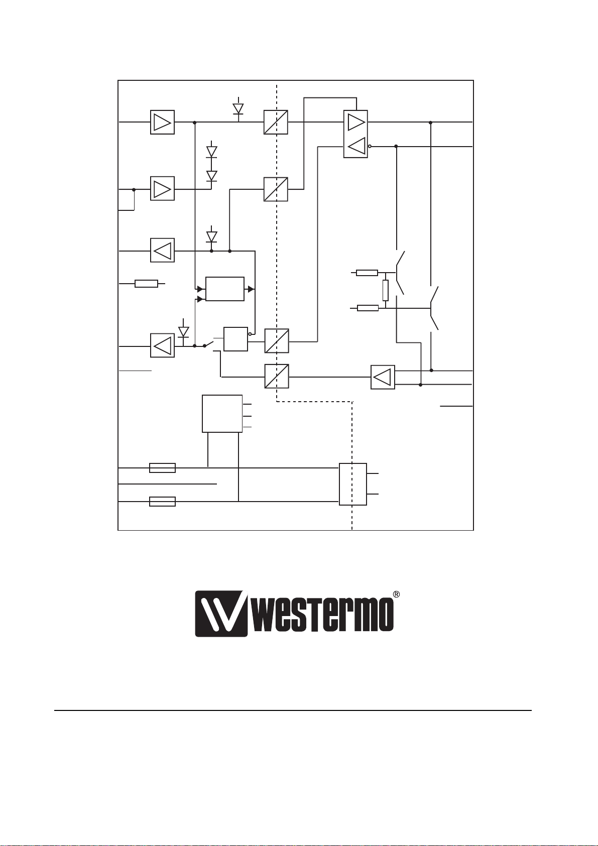
Block diagram
V.11/RS-422
RS-485
X3
TD
RTS
CTS
DCD
DSR
RD
SG
X2
3
A
4
B
3
S3
Trig
RTS
CTS
TD
+5V
B
Bus termination
0V
B
4
S3
2
2
4
5
DCD
8
6
+5V
RD
Activity
S2
3
&
6
7
0V
+12V
+5V
-12V
1
X2
1
A'
2
B'
5
Shield
Power
supply
F1
F2
0V
+5VB
0VB
 Loading...