

Page 1
Omvandlare RS-232 – RS-422/485
Converter RS-232 – RS-422/485
RS-232 – RS-422/485 Wandler
INSTALLATIONSANVISNING
INSTALLATION MANUAL
INSTALLATIONS ANLEITUNG
6042-2002
www.westermo.se
MA-42 AC
MA-42 DC
©
Westermo Teleindustri AB • 1999 • REV. A
Galvanic
Isolation
Transient
Protection
Balanced
Transmission
CE
Approved
Page 2

8 6042-2002
Specifications
Transmission Asynchronous, full/half duplex or simplex
Interface 1 EIA RS-232-C/RS-423-A
CCITT V.24/V.10
25-position D-sub female, DCE
Interface 2 EIA RS-422/RS-485/CCITT V.11
Data rate Up to 115,2 kbit/s
Indicators Power, RD, DCD, CTS, RTS, TD
Insulation Galvanic insulation with opto-coupler
(data transmission) and transformer (supply)
Insulation voltage 1500V
Overvoltage protection Mains: Breakdown voltage 440V at
230V AC and 220V at 115V AC
Interface 2: Breakdown voltage transmitter
and receiver 7V
Surge capacity 0.6 kW for 1ms
Power supply Switchable 115/230V +15/–10% 48-62Hz
Fuse 100 mA fast 5x20mm
Power consumption Max 25 mA at 230V AC
Temperature range 5–50°C, ambient temperature
Humidity 0–95% RH, non-condensing
Dimensions 161x53x139 mm (WxHxD)
Weight 0.5 kg
Mounting With rubber pads or screws. Screws:
Remove the two "keyholes" on the bottom of the case.
DANGER! DO NOT OPEN CONNECTED UNIT
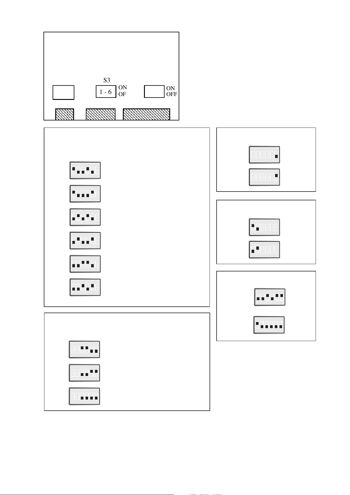
Switch settings
The MA-42 can through different switch settings be adapted to a variety of running
conditions. To set the switches, open the plastic case by placing and turning a screw-driver between top and bottom at the rear of the case.
12345
V.24/RS-232-C
CONNECTION
LINE
CONNECTION
Page 3
96042-2002
Transmitter
Factory settings
Transmitter
activated
by
RTS RTS RTS
RTS Always high
DTR DTR
DTR Always high
RTS
DTR
DTR
CTS
Controlled
by
DCD
Controlled
by
S2
S2
S2
S2
S3
ON
123456
ON
123456
ON
123456
Termination (4-wire)
Termination (2-wire)
No termination
S3
S3
S3
Termination
with fail-safe
1)
ON
123456
Always high Always lowAlways active
S2
ON
123456
Always high Always highAlways active
S2
ON
123456
ON
123456
CTS-delay
0ms
S2
S2
20ms
S2
ON
123456
ON
123456
Selection of 2-/4-wire
4-wire
S3
2-wire
S3
ON
123456
ON
123456
ON
123456
S1 Selection of power supply 115V/230V AC
S2 Selection of signal activating the transmitter
Selection of signal controlling DCD
Selection of CTS delay
S3 Selection of termination with fail-safe 1)
Selection of 2- or 4-wire communication
1) The fail-safe function forces the
signal state of the receiver to
OFF when the connected
transmitter is in tri-state
(transmitter inactive).
The receiver located furthest
away shall be terminated.
ON
OFF
S3
1 - 6
ON
OFF
S1 S2
1 - 6
ON
123456
ON
123456
ON
123456
Page 4

10 6042-2002
Connections
Line connection
(5-position screw-terminal)
Direction
No.
CCITT V.11
Description
Receiver 1 A’ R+
Receiver 2 B’ R–
Transmitter 3 A T+
Transmitter 4 B T–
5 Shield
I 2 103 TD/Transmitted Data
O 3 104 RD/Received Data
I 4 105 RTS/Request To Send
O 5 106 CTS/Clear To Send
O 6 107 DSR/Data Set Ready
– 7 102 SG/Signal Ground
O 8 109 DCD/Data Carrier Detect
1 20 108/2 DTR/Data Terminal Ready
Description
Terminal connection (DCE)
(RS-232-C/V.24, 25-Position D-sub, female)
I = Input O = Output on MA-42.
Direction 1)
Pin
no.
CCITT V.24
Circuit number
Line connection
1) If shielded cable is used, connect the shield only at one end to avoid ground currents.
Transmission range (interface 2)
Use twisted pair cable. Max transmission range 1200m.
(cable specifications 0.3mm
2
and capacitance 42pF/m).
The transmission range will increase if a cable with lower capacitance and larger
diameter is used.
Use shielded cable in heavy industrial environments.
4-wire 2-wire
1
2
3
4
5
3
4
5
A’
B’
A
B
A
B
A’
B’
Receiver
Receiver
A/A’
B/B’ B/B’
A/A’
Twisted pairs
Twisted pairs
MA-42 MA-42
Transmitter
Transmitter
RS-422
equipment
RS-485
equipment
Transmitter/
Receiver
Transmitter/
Receiver
Shield 1) Shield 1)
The definations R+/R–,T+/T– can be
various between different manufactures.
Page 5

116042-2002
MA-42 DC
Specifications
Power supply 12–36V DC
Power consumption: Max 2W
Insulation: 1000V
Fuse F1: 1.6A fast 5x20 mm
All other specifications according to MA-42 AC
Switch settings
According to MA-42 AC
Connections
According to MA-42 AC, except power supply
Connection
no.
Power
Supply
1 + Voltage
2 – Voltage
3
POWER
12-36VDC
123
LINE
CONNECTION
12345
V.24/RS-232-C
CONNECTION
Page 6

12 6042-2002
Hints
The MA-42 uses the RS-422/485 interface.
RS-422/485 was designed for multidrop applications. When a system is installed it should
form a bus structure (see diagrams). Star shaped networks should never be created,
there are other Westermo products designed to work in star net applications. For
correct installation an RS-422/485 network should be terminated at the correct points.
The recommendation is to terminate the receivers at both end of network.
See diagrams for details of how this is done with RS-485 (2 wire) and RS-422 (4 wire).
On 4 wire systems when the MA-42 is working as a slave, the transmitter is linked to
the same bus as all the other slaves transmitter. A status signal (RTS or DTR) is used to
control the MA-42’s transmitter, to ensure that only one slave is active on the bus at the
same time. The status signal is also used to control direction for RS-485 (2 wire) transmission.
If any problems do occur on set up of the MA-42, the LED’s will be helpful.
• PWR: The unit has power.
• RD: Data received on the RS-422/485 interface.
• DCD: Simulated carrier due to the setting of S2.
• CTS: Follows RTS.
• RTS: Indicates that the RS-422/485 transmitter is activated.
• TD: Data received on the RS-232 interface.
Page 7

136042-2002
Max 1200 metres
Max 32 connections
Max 32 connections
Shortest possible max 0.3 metres
Termination
3
4
4
14231423143
343 43
1
2
3
4
Termination
Page 8

6042-2002 01.03 TunaTryck AB, Eskilstuna, Sweden
Westermo Teleindustri AB • S-640 40 Stora Sundby, Sweden
Phone +46 16 42 80 00 Fax +46 16 42 80 01
E-mail: info@westermo.se • Westermo Web site: www.westermo.se
Westermo Teleindustri AB have distributors in several countries,
contact us for further information.
Westermo Data Communications GmbH
Bruchsaler Straße 18, 68753 Waghäusel
Tel.: +49(0)7254-95400-0 • Fax.:+49(0)7254-95400-9
E-Mail: info@westermo.de • Web: www.westermo.de
Westermo Data Communications Ltd
Unit 14 Talisman Business Centre • Duncan Road
Park Gate, Southampton • SO31 7GA
Phone: +44(0)1489 580 585 • Fax.:+44(0)1489 580586
E-Mail: sales@westermo.co.uk • Web: www.westermo.co.uk
Subsidiaries
V.11/RS-422
RS-485
V.24/RS-232
Block diagram
SG
Power supply
A'
B'
A
B
Shield
TD
RTS
DTR
DCD
CTS
RD
DSR
PG
2)
7
0V
PE
1
2
3
4
PWR
TD
+5V
DCD
+5V
2
4
20
8
1
2
3
4
5
RTS
20mS
CTS
RD
5
3
+5V
S3
+5VB
6
1K
100R
1K
S2
6
0VB
5
F1
R44R45
1)
1
PE
1)R46
PE 0VB
0VB
+5VB
0VB
+12V
S2
6
4
S3
3
5
S3
1
2
-12V
0V
+5V
2)
Insulated power supply
1) 0 Ω resistors R45 and R46 are normally not mounted.
2) Metal housing on D-sub is connected to PE.
 Loading...