

Page 1

Korthållsmodem
Short haul modem
Kurzstreckenmodem
INSTALLATIONSANVISNING
INSTALLATION MANUAL
INSTALLATIONS ANLEITUNG
6012-2001
www.westermo.se
MA-12 AC
MA-12 DC
©
Westermo Teleindustri AB • 1999 • REV. A
Galavanic
Isolation
CE
Approved
Balanced
Transmission
Transient
Protection
Page 2

8 6012-2001
Specifications MA-12
Transmission Asynchronous, full/half duplex or simplex
Interface 1 EIA RS-232-C/CCITT V.24/V.28
25-position D-sub female, DCE
Interface 2 ±10mA balanced current loop
Data rate Up to 38 400 bit/s
Indicators Power, RD, DCD, RTS, TD
Isolation Galvanic insulation with opto-coupler (data transmission)
and transformer (supply)
Insulation voltage 1500V
Overvoltage protection Nät: Breakdown voltage 440V at 230V AC and
220V at 115V AC
Interface 2: Breakdown voltage
transmitter 15V and receiver 5.8V
Surge capacity 0.6 kW for 1 ms
Power supply Switchable 115/230V +15/–10% 48–62Hz
Fuse 100 mA fast 5x20 mm
Power consumption Max 4VA at 230V
Temperature range 5–50°C, ambient temperature
Humidity 0–95% RH, non-condensing
Dimensions 161x139x53 mm
Weight 0.5 kg
Mounting With rubber pads or screws.
Screws: Remove the two ’’keyholes’’ on the bottom
of the case
Page 3
96012-2001
Danger! Do not open connected unit
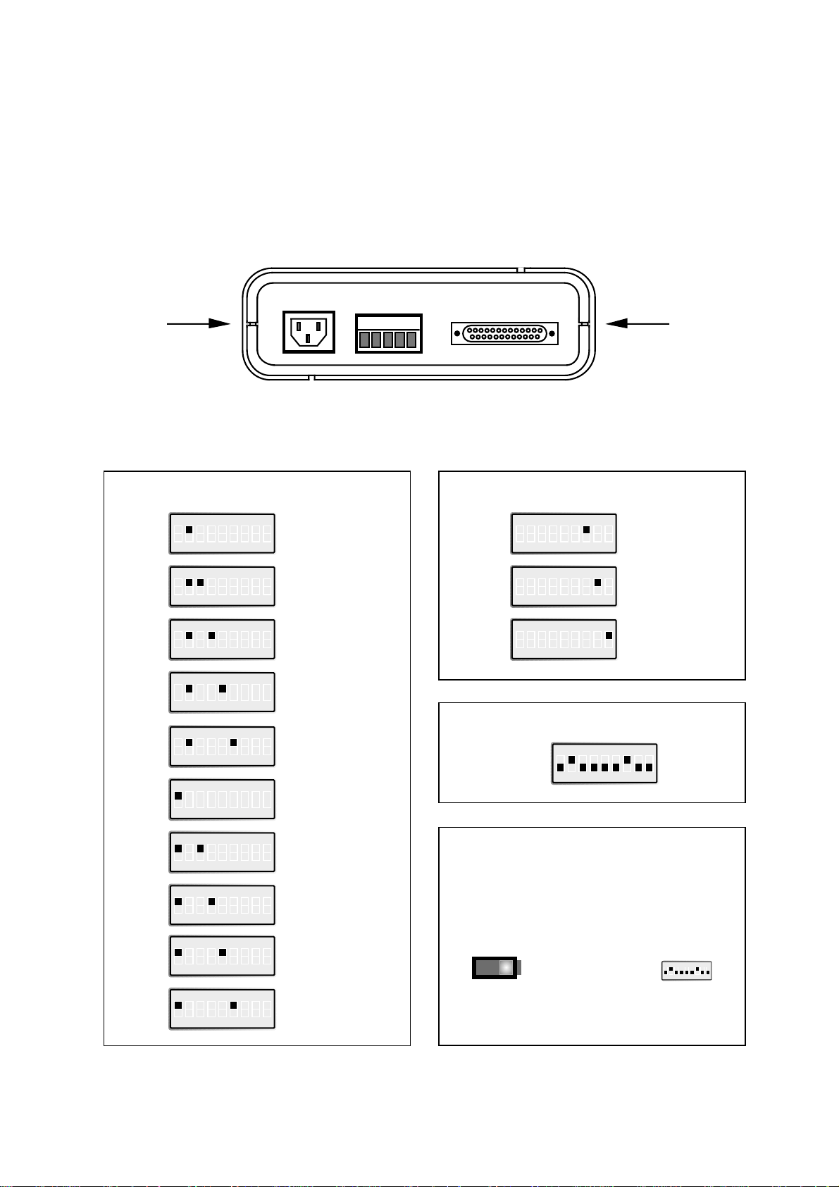
12345
LINE
CONNECTION
V.24/RS-232-C
CONNECTION
Switch settings
Transmitter (carrier) activated by
ON
123456789
S1
Always active
ON
123456789
S1
AUX
ON
123456789
S1
SRS
ON
123456789
S1
RFR
ON
123456789
S1
RTS
ON
123456789
S1
DTR
ON
123456789
S1
DTR and AUX
ON
123456789
S1
DTR and SRS
ON
123456789
S1
DTR and RFR
ON
123456789
S1
DTR and RTS
CTS controlled by
ON
123456789
S1
RTS
ON
123456789
S1
Always high
ON
123456789
S1
DCD
ON
123456789
S1
Factory settings
ON
1 2 3 4 5 6 7 8 9
S2
S1
ON
OFF
S1 Selection of signal activating transmitter (carrier)
Selection of signal controlling CTS
S2 Selection of power supply 115/230V AC
Switch settings MA-12
The MA-12 can through different switch settings be adapted to a variety of running conditions. To set the switches, open the plastic case by placing and turning a screw-driver
between top and bottom at the rear of the case.
Page 4

10 6012-2001
Connections
Line connections
(5-pos. screw-terminal)
Direction No. Description
Receiver 1 R+
Receiver 2 R–
Transmitter 3 T+
Transmitter 4 T–
5 Shield
Terminal connection (DCE)
(RS-232-C/V.24/V.28, 25-position D-sub, female)
Direction 1) Pin CCITT V.24 Description
no. Circuit number
I 2 103 TD / Transmitted Data
O 3 104 RD / Received Data
I 4 105 RTS / Request to Send
O 5 106 CTS / Clear to Send
O 6 107 DSR / Data Set Ready
– 7 102 SG / Signal Ground
O 8 109 DCD / Data Carrier Detect
I 11 – AUX / Auxiliary
I 19 120 SRS / Secondary Request to Send
I 20 108/2 DTR / Data Terminal Ready
I 25 133 RFR / Ready For Receiving
1) I = Input O = Output on MA-12
Page 5

Anslutning
According to MA-12AC, exept power supply
Connection no. Power supply
1 + Voltage
2 – Voltage
3
116012-2001
MA-12 DC
Specifications
Switch settings
According to MA-12AC
Power supply 12-36V DC
Power consumption Max 3W
Insulation 1000V
Fuse F1 1,6A fast 5x20 mm
All other specifications according to MA-12 AC
123
POWER
12–36V DC
LINE
CONNECTION
V.24/RS-232-C
CONNECTION
Transmission range (interface 2)
Cable Transmission rate bit/s
42pF/m 600 1200 2400 4800 9600 19200 38400
0,3mm
2
18000 m 12000 m 8000 m 5000 m 2500 m 1000 m 500 m
Line connection
1) If shielded cable is used, connect the shield only at one end to avoid ground currents.
MA-12
Receiver
1
2
3
4
5
T+
T–
R+
R–
Transmitter
Shield 1)
Tvinnade trådpar
Ex MA-12, MA-19....
Transmitter
R+
R–
T+
T–
Receiver
3
4
1
2
12345
Page 6

12 6012-2001
Hints
MA-12 are compatible with all asyncronous Westermo modem.
The RS-232 interface on the MA-12 is configured as DCE (Data Communication Equip-
ment). Most printers, PC’s and terminals are set as DTE (Data Terminal Equipment).
Some recommendation of cable configurations are given below.
If any problems do occur on set up of the MA-12, the LED’s will be helpful.
• PWR: The unit has power.
• RD: Data received on line interface.
• TD: Data received on RS-232 interface.
• DCD: Carrier indication, must be on for transmission.
• RTS: Indicates the carrier control status.
A good way to check the MA-12 is to carry out a loop back test. Connect
T+ to R+ and T– to R–. Connect the RS-232 port to a terminal. When
keys are pressed on the terminal you should receive the echo on screen.
The TD & RD lights will both flicker simultaneously as you press the keys.
DTE MA-12 DCE MA-12 9-pos. PC MA-12
12345
1
2
3
4
5
6
7
8
9
10
11
12
13
14
15
16
17
18
19
20
21
22
23
24
25
10
11
12
13
14
15
16
17
18
19
20
21
22
23
24
25
1
2
3
4
5
6
7
8
9
10
11
12
13
14
15
16
17
18
19
20
21
22
23
24
25
1
2
3
4
5
6
7
8
9
1
2
3
4
5
6
7
8
9
10
11
12
13
14
15
16
17
18
19
20
21
22
23
24
25
1
2
3
4
5
6
7
8
9
1
2
3
4
5
6
7
8
9
10
11
12
13
14
15
16
17
18
19
20
21
22
23
24
25
Page 7

136012-2001
OWN COMMENTS
.....................................................................................................................................................................................................................
.....................................................................................................................................................................................................................
.....................................................................................................................................................................................................................
.....................................................................................................................................................................................................................
.....................................................................................................................................................................................................................
.....................................................................................................................................................................................................................
.....................................................................................................................................................................................................................
.....................................................................................................................................................................................................................
.....................................................................................................................................................................................................................
.....................................................................................................................................................................................................................
.....................................................................................................................................................................................................................
.....................................................................................................................................................................................................................
.....................................................................................................................................................................................................................
.....................................................................................................................................................................................................................
.....................................................................................................................................................................................................................
Page 8

Block digram
V.24/V.28/RS-232
DTR
AUX
SRS
RFR
RTS
CTS
DCD
RD
TD
5
4
3
2
1
DSR
SG
PG
Power supply
1) 0 Ω resistor J2 is normally not mounted 2) Metal housing on D-sub is connected to 0V
Insulated power supply
Line
R+
R–
T+
T–
PWR
Shield
PE
J1
1
7
6
2
3
8
5
4
25
19
11
20
+12V
X3 S1
1
2
3
4
5
6
7
8
9
RD DCD
TD
+12V
0V
2)
1) J2
+12V
+12V
RTS
F1
+12V
0V
–12V
OV
6012-2001 10.00 TunaTryck AB, Eskilstuna, Sweden
Westermo Teleindustri AB • S-640 40 Stora Sundby, Sweden
Phone +46 16 612 00 Fax +46 16 611 80
E-mail: info@westermo.se • Westermo Web site: www.westermo.se
Westermo Teleindustri AB have distributors in several countries,
contact us for further information.
Westermo Data Communications GmbH
Bruchsaler Straße 18, 68753 Waghäusel
Tel.: +49(0)7254-95400-0 • Fax.:+49(0)7254-95400-9
E-Mail: westermo.germany@t-online.de
Westermo Data Communications Ltd
Unit 14 Talisman Business Centre • Duncan Road
Park Gate, Southampton • SO31 7GA
Phone: +44(0)1489 580 585 • Fax.:+44(0)1489 580586
E-Mail: sales@westermo.co.uk • Web: www.westermo.co.uk
Subsidiaries
&
Volt
sel
115/
230V
 Loading...