

Page 1
Redundant linjedelare
Optisk fiber – RS-422/485
Redundant line splitter
Fibre-optic – RS-422/485
Redundanter Glasfaser Leitungsteiler
– RS-422/485
INSTALLATIONSANVISNING
INSTALLATION MANUAL
INSTALLATIONS ANLEITUNG
6073-2011
www.westermo.se
LD-64F
©
Westermo Teleindustri AB • 2001 • REV. C
Galvanic
Isolation
Transient
Protection
Balanced
Transmission
CE
Approved
Page 2

12 6073-2001
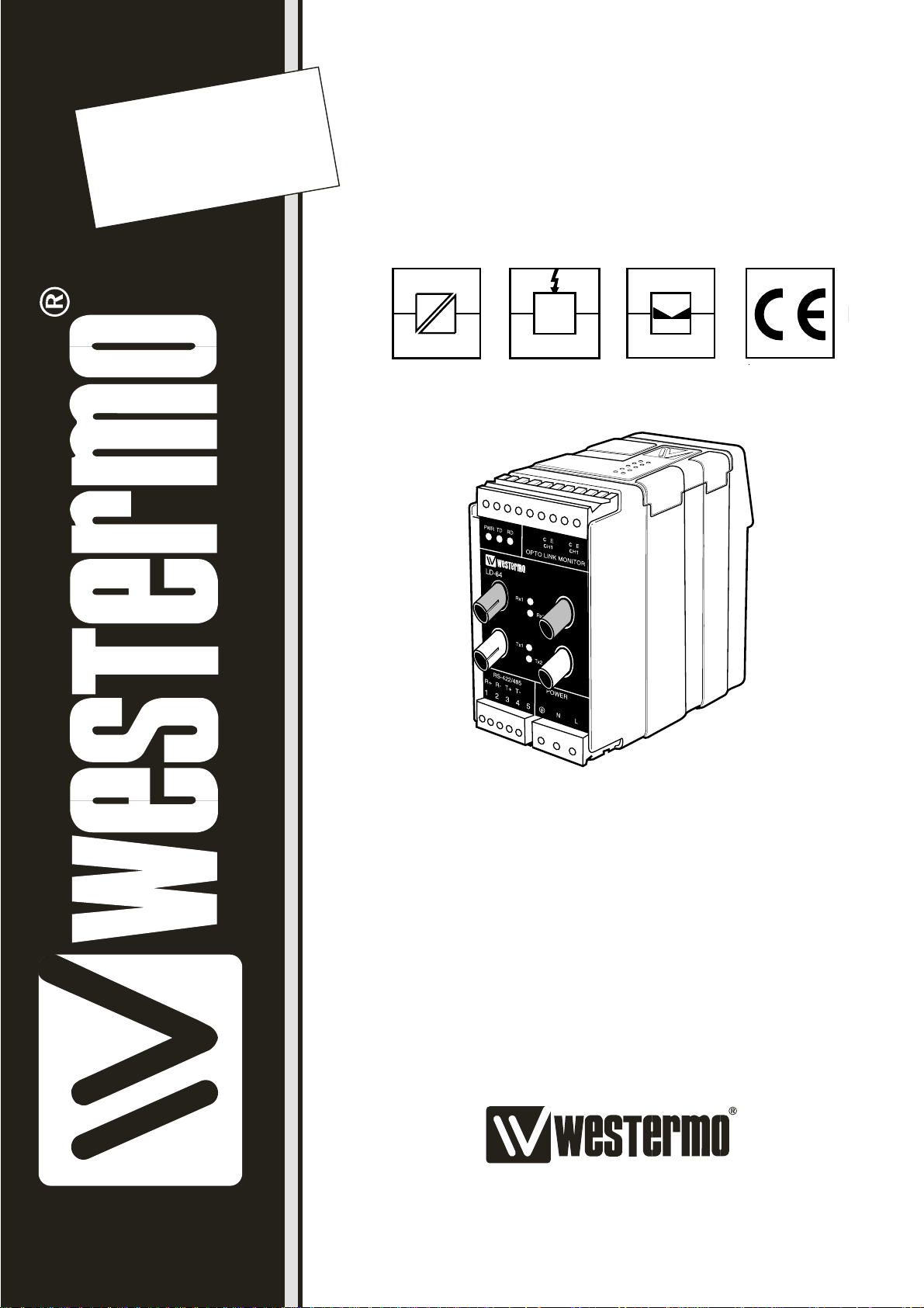
LEDs for indication on LD-64F
• PWR: Indicates that the converter has power.
• TD: Indicates that the converter is receiving data on RS-422/485 side.
• RD: Indicates that the converter is sending data on RS-422/485 side.
• Rx1: Indicates received data on fiber channel 1.
• Rx2: Indicates received data on fiber channel 2.
• Tx1: Indicates that the converter is sending data on fiber channel 1 from RS-422/485 side.
• Tx2: Indicates that the converter is sending data on fiber channel 2 from RS-422/485 side.
Specifications LD-64F
Transmission Asynchronous*, full/half duplex or simplex
Interface 1 EIA RS-422/RS-485/ITU-T V.11
5-position screw block
Interface 2 4 ST-connectors, see table of power budget
Data rate 500 kbit/s – 1.5 Mbit/s
Indicators Power, TD, RD, TX1, TX2, RX1, RX2
Temperature range 5–50°C, ambient temperature
Humidity 0–95% RH without condensation
Dimension 55x100x128 mm (WxHxD)
Weight 0.6 kg AC / 0.3 kg DC
Mounting On 35 mm DIN-rail
Power supply alternatives
Model description
LD-64F LD-64F LD-64F LD-64F LD-64F
AC 115V AC DC 36–55V DC 110V DC
Power supply 230 V AC 115 V AC 24 V DC 48 V DC 110 V DC/80 V AC
+15/–10% +15/–10% +50/–50% +15/–25% +10/–10%
Frequency 48–62 Hz 48–62 Hz – – –/48–62 Hz
Fuse, F2 100 mA S 100 mA S 1.6 A S 1.6 A S 1 A T/1 A T
5x20 mm 5x20 mm 5x20 mm 5x20 mm –/–
Littelfuse Littelfuse Littelfuse Littelfuse Wickmann
Power consumption 25 mA 50 mA 3 W 3 W 30 mA
Transient protection
Power/Line Yes/– Yes/– –/– –/– Yes/–
Isolation RMS
Power supply 3 000 V 3 000 V 1 500 V 1 500 V 3 000 V
* Synchronous protocols can be transmitted under certain circumstances.
See ”selection of bits” page 17.
Page 3

136073-2001
Description LD-64F
LD-64F offers redundant fibre optic communication on RS-422/485 in a multi-drop
network. LD-64F is a high-speed version of LD-64 and data rates from 500 kbit/s
up to 1.5 Mbit/s is possible.
Both multi mode and single mode fibre versions are available. All fibre optic connections
are of the ST-type. Plastic fibre can be used for very short distances (<20 meters).
The maximum transmission distance is calculated from the available power budget of
the modems and the attenuation of the cable, splice joints and connectors. Distances
up to 25 km can be reached using single mode fibres.
The LD-64F is arranged in a master slave configuration with the fibre both starting and
finishing at the master unit. Only one master can be configured on a loop at any time.
There are two F/O channels on each unit, each with a separate transmitter and receiver.
The front cover has 7 LED’s to indicate the state of the various communication paths.
The LD-64F is equipped with a redundant logic system which will control the flow of the
data during fault conditions. If a break is detected on a fibre or a pair of fibres the data
will be re-routed through channel 2. This operation will take approximately 4 ms.
All data in this 4 ms will be lost and will need to be resent.
As with all other Westermo products the LD-64F provides a high level of galvanic
isolation on the power supply side through transformers and also on the alarm side
through optocouplers.
All the operating parameters are set-up via DIP switches located under the lid on the
top of the unit.
Indication and alarm outputs are provided at the master and at the slaves either side of
the fault. the indication and alarm outputs will continue to operate as long as the fault
persists.
The LD-64F is available in a variety of supply voltage in both AC and DC.
Page 4

14 6073-2011
Description of redundancy
LD-64F is connected through two parallel fibre optical rings, ring 1 and ring 2. The ring
topology introduces the possibility for the units to handle a fault on a fibre or a fibre pair
and still maintain communication. The units will automatically change the communication
path when a fault is detected. This change can take up to 4ms and all data sent during
this time needs to be resent since the modems do not have any possibility to databuffer.
One modem in the ring needs to be configured as master through switches inside the
unit. The master controls the data and prevents data to be resent through the ring. The
master is also used for monitoring of the fibre rings since all faults detected in the rings
will be sent to the master. This gives possibility to monitor the complete system through
the master unit. The other modems in the ring needs to be configured as slaves and will
be transparent during normal communication.
LD-64F is equipped with alarm signals which is used for indication of fibre interruptions.
Each unit is equipped with two alarm ports, one for each fibre channel. These ports are
marked as CE1 and CE2 on the unit. A fault will close the circuit between indications
“C” and “E” on respective port. The alarm outputs can for example be used for
connection of an external relay. See connections and examples on page 19–20.
An interruption will be detected by the closest unit which will indicate a receiver alarm
and also send the error further to the master unit which will indicate a corresponding
fault for the ring.
For correct function the fibre optic rings needs to be connected correct between
each modem
Ring 1: Tx1 – Rx2 – Tx1 – Rx2 etc.
Ring 2: Tx2 – Rx1 – Tx2 – Rx1 etc.
Page 5

156073-2011
Below follows a number of different fault situations which shows the different alarm
outputs.
The receiver Rx2 at the master modem
detects an interruption on ring 1. Alarm
output CE1 indicates at the master unit.
The receiver Rx2 on slave modem 3
detects an interruption on ring 1. Alarm
signal CE1 indicates at slave modem 3
and also at the master unit.
Link 1
Link 2
CE1
CE2
CE1
CE2
CE1
CE2
CE1
CE2
x
LD-64 Slave 1 LD-64 Master LD-64 Slave 2 LD-64 Slave 3
Link 1
Link 2
CE1
CE2
CE1
CE2
CE1
CE2
CE1
CE2
x
LD-64 Slave 1 LD-64 Master LD-64 Slave 2 LD-64 Slave 3
The receiver Rx1 on slave modem 3
detects an interruption on ring 2. Alarm
signal CE2 indicates at slave modem 3
and also at the master unit.
Link 1
Link 2
CE1
CE2
CE1
CE2
CE1
CE2
CE1
CE2
x
LD-64 Slave 1 LD-64 Master LD-64 Slave 2 LD-64 Slave 3
Slave modem 3 stops working due to
lack of power or other reason. Receiver
Rx2 on slave modem 1 and receiver Rx1
on slave modem 2 detects interruptions.
Alarm signal CE1 indicates on slave
modem 1 and CE2 indicates on slave
modem 2. Both CE1 and CE2 indicates
on master modem.
Link 1
Link 2
CE1
CE2
CE1
CE2
CE1
CE2
CE1
CE2
LD-64 Slave 1 LD-64 Master LD-64 Slave 2 LD-64 Slave 3
The receiver Rx1 on slave modem 3 and
receiver Rx2 on slave modem 1 detects
interruptions. Alarm signal CE2 indicates
on slave modem 3 and CE1 indicates on
slave modem 1. Both CE1 and CE2
indicates at the master unit.
Link 1
Link 2
CE1
CE2
CE1
CE2
CE1
CE2
CE1
CE2
x
x
LD-64 Slave 1 LD-64 Master LD-64 Slave 2 LD-64 Slave 3
Page 6

16 6073-2011
50/125 µm 3.0 dB/km 1.0 dB/km
62.5/125 µm 3.5 dB/km 1.2 dB/km
100/140 µm 4.0 dB/km
9/125 µm 0.5 dB/km
Fibre
Attenuation
at 820 nm
Attenuation
at 1300 nm
Attenuation
at single mode (1300 nm)
Attenuation in fibre cable
The values below can differ depending on quality and manufacturer of the fibre-optic
cable.
Attenuation in connectors Attenuation in splice
0.2–0.4 dB Fusion 0.1 dB
Mecanical 0.2 dB
50/125 16.6 dB 14.6 dB
62.5/125 18.6 dB 15.1 dB
100/140 25.9 dB
9/125 12.3 dB
50/125 10.7 dB 8.1 dB
62.5/125 14.5 dB 11.6 dB
100/140 20.6 dB
9/125 6.3 dB
Unit
820 nm 1300 nm single mode
Unit
820 nm 1300 nm single mode
Min. budget Typ. budget
Power budget
”Min. budget” states the minimum guaranteed power budget. Experience shows however that the
typical value is in the range of the indicated ”Typ. budget”.
Fibre
Fibre
Page 7

176073-2011
••• •
•• • •
•••
••• •
•••
•••
10 10 10 11 11 119
Supervision table when selecting data bits
7 bits
8 bits
No parity
Parity
1 stop bit
2 stop bits
Number of bits
Turning Time / Data rate /
Connected units
S1
ON
123456789
S1
ON
123456789
S1
ON
123456789
S1
ON
123456789
20
Number**
of units
20
20
20
Selection of 2- or 4-wire
4-wire
S1
ON
123456789
2-wire
S1
ON
123456789
Selection of Master/Slave
Master
S1
ON
123456789
Slave
S1
ON
123456789
Selection of bits
9
S1
ON
123456789
10
S1
ON
123456789
11
S1
ON
123456789
*
S1
ON
123456789
2-wire RS-485 or 4-wire RS-422.
Switch settings LD-64F
0.7 µs 1.5 Mbit/s
Turning-
time
Transmission*
rate
0.8 µs 1.2 Mbit/s
1 µs 1.0 Mbit/s
2 µs 500 kbit/s
* Use this setting for synchronous or other
asynchronous protocols.
The transmitter will be active from the
startbit to 10 bit-times after the last high
databit.
Please note that only one master can be
used per system.
*) For other speeds please contact Westermo
**) Number of units is depending on the data rate and the total
system. "Number of units" means a typical value that can be
changed depending on the structure of the total system.
S1:3, 6 and 7 is not used.
Page 8

ON
12345
ON
12345
ON
12345
18 6073-2011
Termination with fail-safe
Termination (2-wire)
S2
Termination (4-wire)
S2
No termination
S2
Transmitted power channel 1
Low
S2
High
S2
Transmitted power channel 2
Low
S3: 2–4 not used
The fail-safe function forces the signal state of the receiver
to OFF when the connected transmitter is in tri-state
(transmitter inactive). The receiver located furthest away
shall be terminated.
S3
High
S3
ON
1234
ON
1234
S1:1-9
ON
12345
ON
12345
Factory settings
S1
ON
123456789
S3
ON
1234
S2
ON
12345
S3:4-1
S2:1-5
1
2
3
4
5
6
7
8
9
Page 9

196073-2011
Connections LD-64F
Line connection
(5-position screw-terminal)
Direction Connection ITU-T V.11
nr. Description
Receiver 1 A’ (R+)
Receiver 2 B’ (R–)
Transmitter 3 A (T+)
Transmitter 4 B (T–)
5 Shield
Power connection
LD-64F DC
2-position screw-terminal
Screw Power-
no. supply
1 – Voltage
2 + Voltage
Power connection
LD-64F AC
(3-position screw-terminal)
Connection
Power
supply
L 115*/230 V
N AC power
PE/Protective Earth
* LD-64F 115 V
Power connection
LD-64F 110V DC
(3-position screw-terminal)
Connection
Power
supply
L + Voltage
N – Voltage
Not connected
The definations R+/R–, T+/T– can be various between
different manufactures.
Alarm signals
Upon failure the circuit between the contacts ”C” and ”E” is closed. This circuit can
be used to generate an external alarm signal
by connecting an external relay as shown on
page 20. Please note that the maximum allow
voltage/current is 30 V/80 mA.
TD RD C EPWR
LD-64
RS-422/485 POWER
R+
R- T+ T-
12345 LN
Ch1
OPTO LINK MONITOR
Rx1
Rx2
Tx1
Tx2
CE
Ch2
Page 10

20 6073-2001
Fibre optic connection
12345 LN
RS-422/485 POWER
R+
Rx2
Tx1
Tx2
R- T+ T-
12345 LN
RS-422/485 POWER
R+
Rx2
Tx1
Tx2
R- T+ T-
R
+
RS-422
equipment
R
–
T+T
–
RS-485
equipment
T
+T–
*) The designations T+, T–, R+, R– are not standardised and may vary between different
manufactures. The first step in fault finding is to reverse the cables (swap T+ with T–
and/or R+ with R–). Please note that this should be done only at one end!
**
LD-64F
RX1 RX2
TX2
TX1
RX1 RX2
TX2
TX1
LD-64F LD-64F
RX1 RX2
TX2
TX1
RS-422/485 RS-422/485 RS-422/485
Line connection
The alarm connection can for example be used
to control an external relay.
Alarm connections (Opto Link Monitor)
Upon failure the circuit between the contacts C and E is closed.
Please note that the maximum allowed voltage/current is 30 V/80 mA.
In this example only channel 2 is connected. Under normal operation channel 1 and channel 2
should be connected.
LD-64
Rx1
Rx2
TD RD C EPWR
OPTO LINK MONITOR
Ch1
CE
Ch2
Max 30 V, 80 mA
Relay
+
–
Page 11

216073-2001
OWN COMMENTS
.....................................................................................................................................................................................................................
.....................................................................................................................................................................................................................
.....................................................................................................................................................................................................................
.....................................................................................................................................................................................................................
.....................................................................................................................................................................................................................
.....................................................................................................................................................................................................................
.....................................................................................................................................................................................................................
.....................................................................................................................................................................................................................
.....................................................................................................................................................................................................................
.....................................................................................................................................................................................................................
.....................................................................................................................................................................................................................
.....................................................................................................................................................................................................................
.....................................................................................................................................................................................................................
.....................................................................................................................................................................................................................
.....................................................................................................................................................................................................................
Page 12

6073-2011 01-09 Mälartryck AB, Eskilstuna, Sweden
CHANNEL 3
PWR
RD
TD
DCD2
DCD3
DCD4
CHANNEL 2 POWER
12-36V DC
12345
- +
R+ R- T+ T-
CHANNEL 4
123456789123456789
R+ R- T+ T- T+ T- R+ R-
CHANNEL 3
PWR
RD
TD
DCD2
DCD3
DCD4
CHANNEL 2 POWER
12-36V DC
12345
- +
R+ R- T+ T-
CHANNEL 4
123456789123456789
R+ R- T+ T- T+ T- R+ R-
CHANNEL 3
PWR
RD
TD
DCD2
DCD3
DCD4
CHANNEL 2 POWER
12-36V DC
12345
- +
R+ R- T+ T-
CHANNEL 4
123456789123456789
R+ R- T+ T- T+ T- R+ R-
CHANNEL 3
PWR
RD
TD
DCD2
DCD3
DCD4
CHANNEL 2 POWER
12-36V DC
12345
- +
R+ R- T+ T-
CHANNEL 4
123456789123456789
R+ R- T+ T- T+ T- R+ R-
Application example
Westermo Teleindustri AB • SE-640 40 Stora Sundby,Sweden
Phone +46 16 42 80 00 Fax +46 16 42 80 01
E-mail:info@westermo.se • W estermo W eb site: www.westermo .se
Westermo Teleindustri AB have distributor s in several
countries, contact us for further information.
Westermo Data Communications Ltd
Unit 14 Talisman Business Centre • Duncan Road
Park Gate, Southampton • SO31 7GA
Phone:+44(0)1489 580 585 • Fax.:+44(0)1489 580586
E-Mail:sales@westermo.co.uk • Web:www.westermo.co.uk
Westermo Data Communications GmbH
Goethestraße 67,68753 Waghäusel
Tel.: +49(0)7254-95400-0 • Fax.:+49(0)7254-95400-9
E-Mail:info@westermo.de • Web: www.westermo.de
Westermo Data Communications S.A.R.L.
9 Chemin de Chilly 91160 CHAMPLAN
Tél :+33 1 69 10 21 00 • Fax :+33 1 69 10 21 01
E-mail :infos@westermo.fr • Site WEB:www.westermo.fr
Subsidiaries
 Loading...