

Page 1
Redundant linjedelare
Optisk fiber – RS-232/V.24, RS-422/485
Redundant line splitter
Fibre-optic – RS-232/V.24, RS-422/485
Redundanter Glasfaser Leitungsteiler
– RS-232/V.24, RS-422/485
Coupleur redondant
RS-232/422/485 – Fibre Optique
INSTALLATIONSANVISNING
INSTALLATION MANUAL
INSTALLATIONS ANLEITUNG
MANUEL D'INSTALLATION
6073-2002
www.westermo.se
LD-64 AC
LD-64 DC
©
Westermo Teleindustri AB • 2005
Galvanic
Isolation
Transient
Protection
CE
Approved
Page 2
2 6073-2002
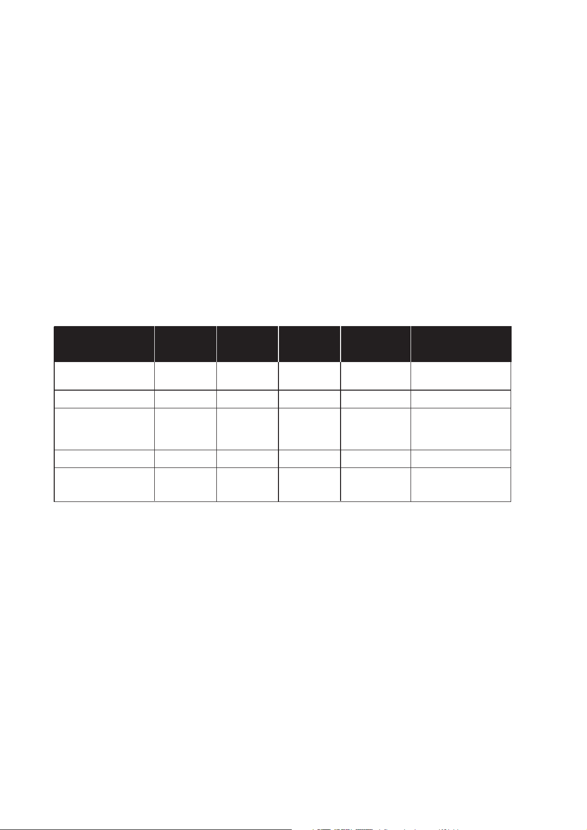
Specifikationer LD-64
Överföring Asynkront*, halv duplex eller simplex
Gränssnitt 1 EIA RS-232/ITU-T V.24 9-polig skruvplint
EIA RS-422/RS-485/ ITU-T V.11 5-polig skruvplint
Gränssnitt 2 4 ST-kontakter, se tabell för effektbudget
Överföringshastighet 2 400 bit/s – 115,2 kbit/s (RS-232-C) 2 400 bit/s – 375 kbit/s
(RS-422/485)
Lysdioder Power, TD, RD, TX1, TX2, RX1, RX2
Temperaturområde 5–50°C, omgivningstemperatur
Fuktighetsområde 0–95% RH utan kondensation
Mått 55x100x128 mm (BxHxD)
Vikt 0,6 kg AC / 0,3 kg DC
Montering På 35 mm DIN-skena
Matningsalternativ
Modellbeteckning
LD-64 LD-64 LD-64 LD-64 LD-64
AC 115V AC DC 36–55V DC HV
Strömförsörjning 230V AC 115V AC 24V DC 48V DC 95–240V AC±%
+15/–10% +15/–10% +50/–50% +15/–25% 110–240V DC±10%
Frekvens 48–62Hz 48–62Hz – – 48–62Hz / –
Säkring, F2 100mA S 100mA S 1,6A S 1,6A S 1A T Wickmann
5x20 mm 5x20 mm 5x20 mm 5x20 mm
Littelfuse Littelfuse Littelfuse Littelfuse
Effektförbrukning 20mA 40 mA 3W 3W 40mA
Isolation, RMS
Matning 3 000V 3 000V 1 500V 1 500V 3 750V
Lysdiodindikeringar LD-64
• PWR: Indikerar att enheten är spänningssatt.
• TD: Indikerar mottagen data på RS-232, RS-422/485 sidan.
• RD: Indikerar sänd data på RS-232, RS-422/485 sidan.
• Rx1: Indikerar mottagen data på fiber kanal 1.
• Rx2: Indikerar mottagen data på fiber kanal 2.
• Tx1: Indikerar sänd data på fiber kanal 1 från RS-232, RS-422/485 sidan.
• Tx2: Indikerar sänd data på fiber kanal 2 från RS-232, RS-422/485 sidan.
* Synkront protokoll kan överföras under vissa förutsättningar.
Se beskrivning ”Val av antal bitar” sid 7.
Page 3

36073-2002
Funktionsbeskrivning LD-64
LD-64 möjliggör en fiberoptisk redundant kommunikation mellan utrustningar med
RS-232/V.24 eller RS-422/485 gränssnitt. Enheten är bestyckad med ST-kontakter och
finns i både multi- och singelmod versioner.
Överföringsavstånd beräknas från tillgänglig effektbudget hos modemen och där
förluster i kabel, kontakter och skarvar är viktiga parametrar. Överföringsavstånd upp
till 25 km är möjligt med singelmodkabel.
LD-64 enheterna kopplas upp i ett ringnät där en enhet konfigureras som master
genom switchinställning. Den redundanta kommunikationen är möjlig genom att varje
enhet har två fiberkanaler med separata sändare och mottagare. Om ett kommunikationsavbrott skulle uppstå på en fiberslinga kopplas kommunikationen automatiskt
över till den andra fiberslingan. Avbrottshanteringen tar ca 4 ms och all data som sänds
under den perioden förloras och måste återsändas. Enheten har 7 lysdioder som
indikerar dataflöde samt en larmutgång för varje fiberslinga som exempelvis kan styra
ett relä. Respektive larmutgång är aktiverad så länge fiberavbrottet består.
Som alla Westermo produkter erbjuder LD-64 galvanisk isolation genom transformatorn på matningssidan samt även med optokopplare på larmsidan. Det är dock ingen
galvanisk isolation mellan RS-232/V.24 och RS-422/485 och det är endast möjligt att
använda en port åt gången.
LD-64 är protokolloberoende vilket gör det möjligt att använda enheterna i system
som använder sig av Modbus, Profibus eller exempelvis Bitbus kommunikationsprotokoll.
Alla inställningar görs enkelt genom switchar som är lättillgängliga på varje enhet.
LD-64 är tillgänglig med både AC- och DC-matning, se ytterligare information under
specifikationer.
Page 4

4 6073-2002
Beskrivning av redundans
LD-64 ansluts genom två parallella fiberoptiska ringar, ring 1 och ring 2. Ring topologin
innebär att enheterna kan hantera avbrott på någon av fiberringarna och ändå bibehålla
kommunikationen. När ett fel detekteras på någon fiber eller ett fiberpar kommer
enheterna automatiskt att ändra kommunikationsväg för att bibehålla kommunikationen
med samtliga enheter. Denna omställningstid kan ta upp till 4 ms och all sänd data under
denna tid måste återsändas då modemen saknar buffringskapacitet.
Ett modem i slingan måste konfigureras som master genom switchinställning och har till
uppgift att dels hindra data från att återsändas i ringen och även att användas för
monitorering av fiberslingan då samtliga feldetekteringar i ringen kommer att sändas till
mastermodemet som då kan användas för kontroll av fiberringarna. Övriga modem i
slingan konfigureras som slavar vilket innebär att dessa är transparanta under normal
kommunikation.
LD-64 är utrustad med alarmsignaler som används för att indikera fiberavbrott.
Varje enhet är utrustad med två alarmutgångar, en för varje kanal. Dessa alarmutgångar
markeras som CE1 samt CE2 på modemet. Vid en indikering kommer kretsen mellan
”C” och ”E” på respektive kanal att slutas. Alarmutgångarna är konstruerade för att
exempelvis anslutas till ett externt relä. Se anslutningar och exempel på sid. 9–10.
Vidare finns även lysdiodindikering för fiberavbrott. Detta för att enkelt kunna lokalisera
avbrottet.
Vid avbrott kommer mottagaren på närmsta enheten att detektera felet och indikera ett
mottagarfel på motsvarande alarmutgång. Vidare kommer även en felindikation att
skickas till mastermodemet som kommer att indikera ett motsvarande ringfel. På detta
vis kan mastermodemets alarmutgångar användas för kontrollera hela fiberringen.
För korrekt funktion krävs att ringarna kopplas korrekt mellan varje modem.
Ring 1: Tx1 – Rx2 – Tx1 – Rx2 etc.
Ring 2: Tx2 – Rx1 – Tx2 – Rx1 etc.
Page 5
56073-2002
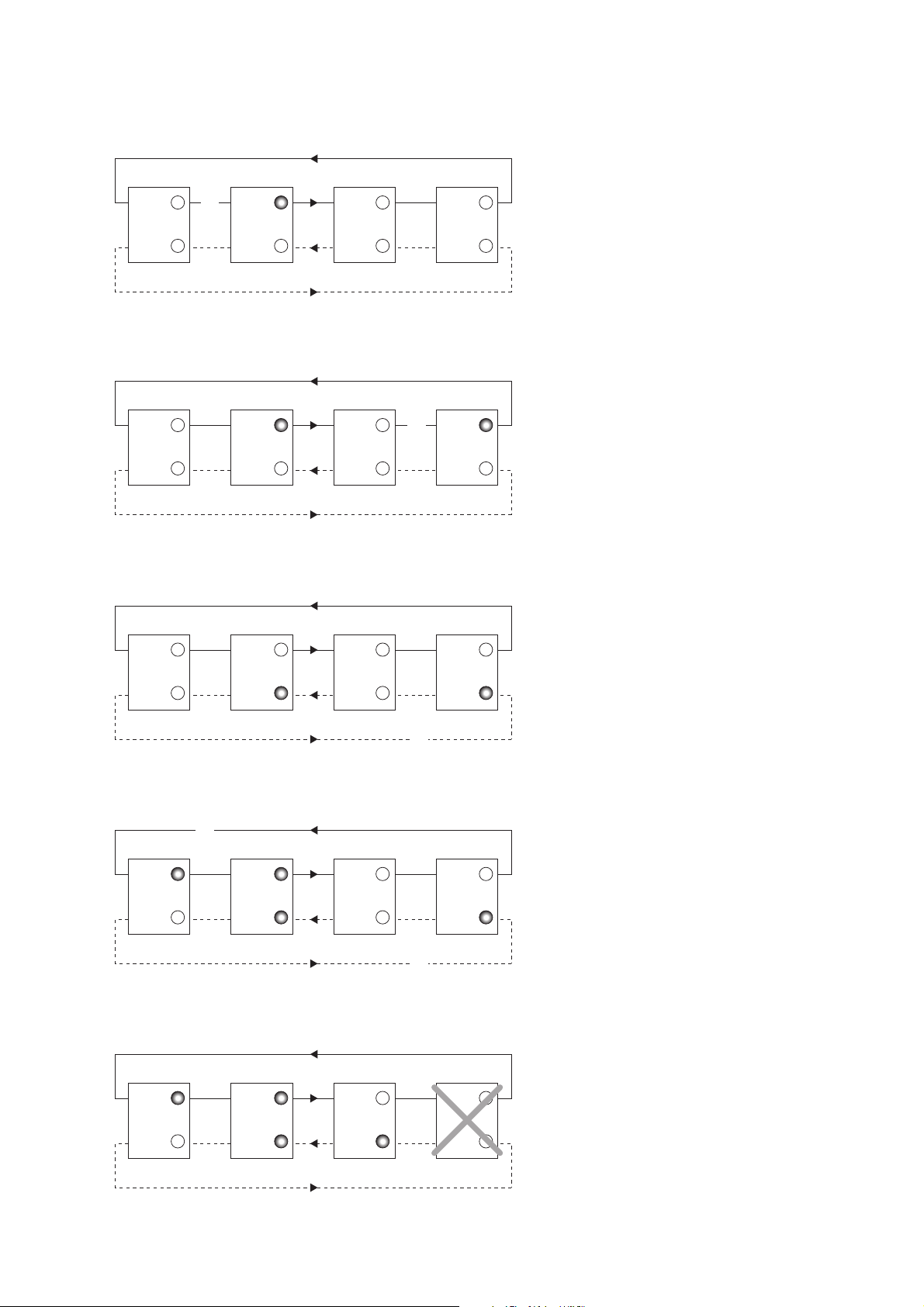
Nedan följer ett antal exempel som visar felindikeringen hos modemen vid olika typer av
fiberavbrott.
Mottagare Rx2 hos master modemet
detekterar ett avbrott på ring 1. Alarmsignal CE1 indikerar på masterenheten.
Mottagare Rx2 på slav modem 3
detekterar ett avbrott på ring 1.
Alarmsignal CE1 indikerar på slav modem
3 samt på masterenheten.
Link 1
Link 2
CH1
CH2
CH1
CH2
CH1
CH2
CH1
CH2
x
LD-64 Slave 1 LD-64 Master LD-64 Slave 2 LD-64 Slave 3
Link 1
Link 2
CH1
CH2
CH1
CH2
CH1
CH2
CH1
CH2
x
LD-64 Slave 1 LD-64 Master LD-64 Slave 2 LD-64 Slave 3
Mottagare Rx1 på slav modem 3
detekterar ett avbrott på ring 2.
Alarmsignal CE2 indikerar på slav modem
3 samt på masterenheten.
Link 1
Link 2
CH1
CH2
CH1
CH2
CH1
CH2
CH1
CH2
x
LD-64 Slave 1 LD-64 Master LD-64 Slave 2 LD-64 Slave 3
Slav modem 3 slutar fungera pga ex.
strömavbrott eller internt fel. Mottagare
Rx2 på slav modem 1 samt mottagare
Rx1 på slav modem 2 detekterar avbrott.
Alarmsignal CE1 indikerar på slav modem
1 och CE2 indikerar på slav modem 2.
Både CE1 och CE2 indikerar på masterenheten.
Link 1
Link 2
CH1
CH2
CH1
CH2
CH1
CH2
CH1
CH2
LD-64 Slave 1 LD-64 Master LD-64 Slave 2 LD-64 Slave 3
Mottagare Rx1 på slav modem 3 samt
mottagare Rx2 på slav modem 1
detekterar avbrott. Alarmsignal CE2
indikerar på slav modem 3 och CE1
indikerar på slav modem 1. Både CE1
och CE2 indikerar på masterenheten.
Link 1
Link 2
CH1
CH2
CH1
CH2
CH1
CH2
CH1
CH2
x
x
LD-64 Slave 1 LD-64 Master LD-64 Slave 2 LD-64 Slave 3
Page 6

6 6073-2002
50/125 16,6 dB 14,6 dB
62,5/125 18,6 dB 15,1 dB
100/140 25,9 dB
9/125 12,3 dB
50/125 µm 3,0 dB/km 1,0 dB/km
62,5/125 µm 3,5 dB/km 1,2 dB/km
100/140 µm 4,0 dB/km
9/125 µm 0,5 dB/km
Fiber
Dämpning
vid 820 nm
Dämpning
vid 1300 nm
Dämpning
vid singelmod (1300 nm)
50/125 10,7 dB 8,1 dB
62,5/125 14,5 dB 11,6 dB
100/140 20,6 dB
9/125 6,3 dB
Enhet
820 nm 1300 nm singelmod
Enhet
820 nm 1300 nm singelmod
Min. budget Typ. budget
Effektbudget
Förluster i fiberoptisk kabel
Nedan angivna värden kan variera beroende på kvalité och fabrikat på den fiberoptiska
kabeln.
Förluster i kontakter Förluster i skarv
0,2–0,4 dB Svetsad 0,1 dB
Mekanisk 0,2 dB
”Min. budget” anger garanterat minsta effektbudget. Erfarenheten visar dock att värdet oftast ligger i
nivå med angivet ”Typ. budget”.
Fiber
Fiber
Page 7
76073-2002
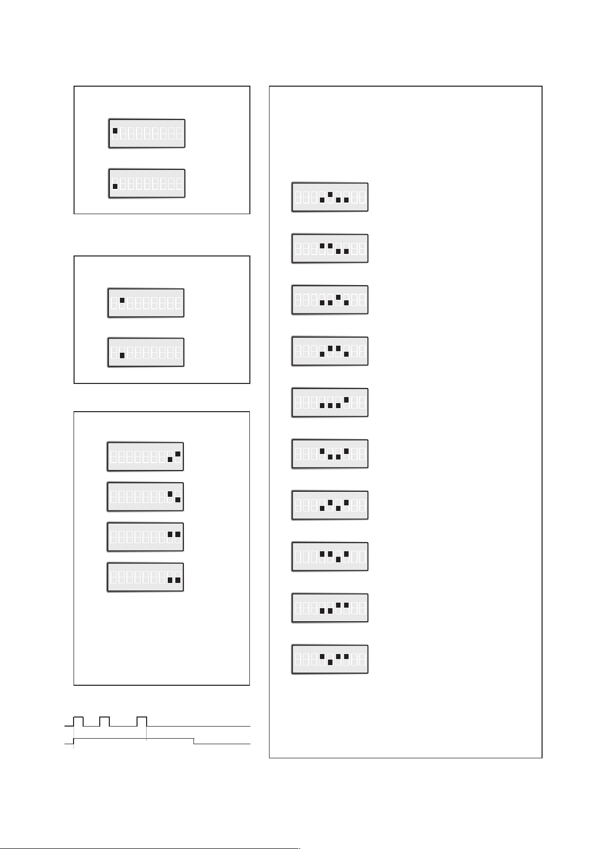
Vändtid/Överföringshastighet
/Antal enheter
S1
ON
123456789
S1
ON
123456789
S1
ON
123456789
S1
ON
123456789
S1
ON
123456789
S1
ON
123456789
S1
ON
123456789
S1
ON
123456789
S1
ON
123456789
S1
ON
123456789
20
Antal**
enheter
20
20
20
20
20
20
15
10
5
Val av 2- eller 4-tråd
4-tråd
S1
ON
123456789
2-tråd
S1
ON
123456789
Val av master/slav
Slav
S1
ON
123456789
Master
S1
ON
123456789
Val av antal bitar
9
S1
ON
123456789
10
S1
ON
123456789
11
S1
ON
123456789
*
S1
ON
123456789
Val av 2-tråd RS-485 eller 4-tråd RS-422. För
RS-232 kan S1:1 ignoreras
Inställningar LD-64
0,4 ms 2 400 bit/s
Vändtid
Överförings-*
hastighet
0,2 ms 4 800 bit/s
0,1 ms 9 600 bit/s
50 µs 19 200 bit/s
25 µs 38 400 bit/s
16 µs 62 500 bit/s
11 µs 93 750 bit/s
9 µs 115,2 kbit/s
6 µs 187,5 kbit/s
3 µs 375 kbit/s
* Denna inställning används för synkrona
och vissa asynkrona protokoll. Sändaren
kommer att vara aktiv från startbiten till
10 bit-längder efter den sista höga
databiten (se exempel under).
Hastigheten sätts till ca 10 ggr den
krävda överföringshastigheten
Observera att endast en master kan användas
per system
Start bit
1 bit = 52µs
1 bit: 1/19 200 = 52µs
Överföringshastighet 19 200
Sändare aktiv
Ställ hastigheten till 187,5 kbit/s
10x52µs = 520µs
↵
Exempel 19 200 bit/s
*) Kontakta Westermo för
högre överföringshastigheter.
**) Kontakta Westermo för
fler antal enheter.
S1:3 används ej.
Page 8

ON
12345
ON
12345
ON
12345
8 6073-2002
••• •
•• • •
•••
••• •
•••
•••
10 10 10 11 11 119
Överföringstabell vid val av databitar
7 bitar
8 bitar
Ingen paritet
Paritet
1 stopp bit
2 stopp bitar
Antal bitar
Terminering med fail-safe
Terminering (2-tråd)
S2
Terminering (4-tråd)
S2
Ingen terminering
S2
Uteffekt kanal 1
Låg
S2
Hög
S2
Uteffekt kanal 2
Låg
Normalt används hög uteffekt. Låg uteffekt används vid
fiberlängder under 100 meter. S3: 2–4 används ej
Fail-safe funktionen tvingar mottagarsignalen till läge OFF
då den anslutna sändaren är i tri-state. Mottagaren längst
bort skall termineras.
S3
Hög
S3
ON
1234
ON
1234
S1:1-9
ON
12345
ON
12345
Fabriksinställning
S1
ON
123456789
S3
ON
1234
S2
ON
12345
Normalt används hög uteffekt. Låg uteffekt används vid
fiberlängder under 100 meter.
S3:4-1
S2:1-5
1
2
3
4
5
6
7
8
9
Page 9
96073-2002
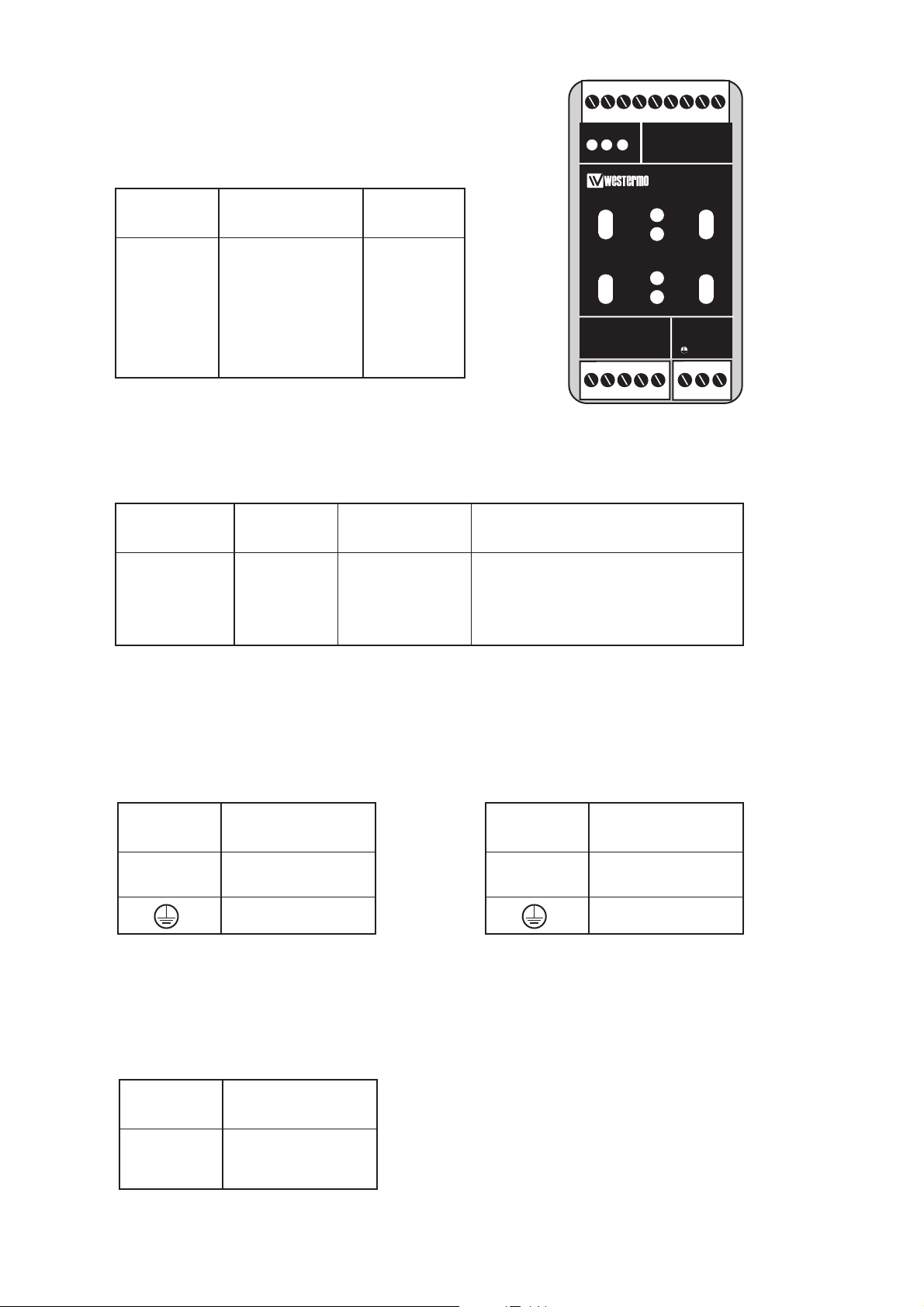
Anslutningar LD-64
Linjeanslutning
(5-polig skruvplint)
Matningsanslutning
LD-64 DC
2-polig skruvplint
Terminalanslutning (DCE)
(RS-232-C/V.24, 9-polig skruvplint)
Riktning Anslutnings ITU-T V.11
nr. Benämning
Mottagare 1 A’ (R+)
Mottagare 2 B’ (R–)
Sändare 3 A (T+)
Sändare 4 B (T–)
5 Skärm
Riktning Skruvplint ITU-T V.24 Beskrivning
nr. Benämning
I 8 103 TD/Transmitted Data
O 7 104 RD/Received Data
– 9 102 SG/Signal Ground
I = Ingång O = Utgång på LD-64
Anslutnings Spännings-
nr. anslutning
1 – Spänning
2 + Spänning
Matningsanslutning
LD-64 AC
3-polig skruvplint
Anslutning
Spännings-
anslutning
L 115*/230V
N AC matning
Skyddsjord
* LD-64 115V
Matningsanslutning
LD-64 HV
3-polig skruvplint
Anslutning
Spännings-
anslutning
L + Spänning
N – Spänning
Skyddsjord
Definitionen R+/R–,T+/T– kan variera mellan olika
tillverkare.
TD RD C EPWR
LD-64
RS-422/485 POWER
R+
R- T+ T-
12345 LN
Ch1
OPTO LINK MONITOR
Rx1
Rx2
Tx1
Tx2
CE
Ch2
Page 10

10 6073-2002
Fiberanslutning
LD-64
RX1 RX2
TX2
TX1
RX1 RX2
TX2
TX1
LD-64 LD-64
RX1 RX2
TX2
TX1
RS-422/485
RS-232 eller
RS-422/485
RS-232 eller
RS-422/485
RS-232 eller
Observera att enheterna skall anslutas kanal 1 till kanal 2 osv.
123456789
Alarmindikering
Alarmanslutningar är polaritetsberoende.
Alarmsignaler
Vid avbrott/fel sluts kretsen mellan kontakterna C och
E. Kretsen kan användas för att styra ett externt relä
som ses på sidan 11. Observera att maximalt tillåten
spänning/ström är 30V/80 mA.
Alarmsignaler
(9-polig skruvplint)
Anslutning Beskrivning Polaritet
1 CH2, E –
2 CH2, C +
3 CH1, E –
4 CH1, C +
OBS
!
C
E
Page 11
116073-2002
LD-64
Rx1
Rx2
TD RD C EPWR
OPTO LINK MONITOR
Ch1
CE
Ch2
SG TD RD
RS-232/V.24
DTE-utrustning
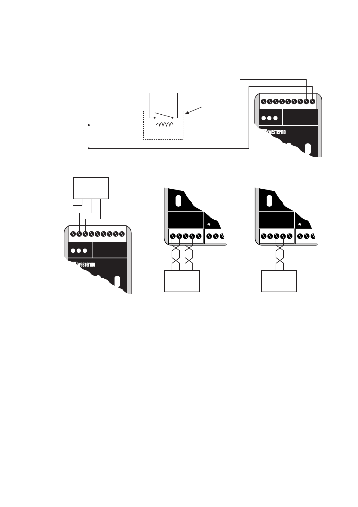
*) Benämningarna T+, T–, R+, R– är inte standardiserade och kan variera mellan olika
tillverkare. Första steget vid felsökning bör alltid vara att skifta respektive kabelpar
(byt T+ med T– och/eller R+ med R–). Observera att kablarna endast ska skiftas i
ena änden.
Max 30V, 80 mA
Relä
I detta exempel används endast kanal 2. Vid normal användning skall kanal 1 och kanal 2 vara anslutna.
+
–
Alarmanslutningen kan exempelvis användas
för att styra ett externt relä.
Alarmanslutningar (Opto Link Monitor)
Vid avbrott/fel sluts kretsen mellan kontakterna C och E.
Observera att maximalt tillåten spänning/ström är 30 V / 80 mA.
12345 LN
RS-422/485 POWER
R+
Rx2
Tx1
Tx2
R- T+ T-
12345 LN
RS-422/485 POWER
R+
Rx2
Tx1
Tx2
R- T+ T-
R
+
RS-422
utrustning
R
–
T+T
–
RS-485
utrustning
T
+T–
**
TD RD C EPWR
CE
Ch1
OPTO LINK MONITOR
Ch2
LD-64
Rx1
Rx2
Page 12

12 6073-2002
LEDs for indication on LD-64
• PWR: Indicates that the converter has power.
• TD: Indicates that the converter is receiving data on RS-232/V.24, RS-485 side.
• RD: Indicates that the converter is sending data on RS-232/V.24, RS-485 side.
• Rx1: Indicates received data on fiber channel 1.
• Rx2: Indicates received data on fiber channel 2.
• Tx1: Indicates that the converter is sending data on fiber channel 1 from RS-232/V.24, RS-485 side.
• Tx2: Indicates that the converter is sending data on fiber channel 2 from RS-232/V.24, RS-485 side.
Specifications LD-64
Transmission Asynchronous*, half duplex or simplex
Interface 1 EIA RS-232/ITU-T V.24
9-position screw block
EIA RS-422/RS-485/ITU-T V.11
5-position screw block
Interface 2 4 ST-connectors, see table of power budget
Data rate 2 400 bit/s – 115.2 kbit/s (RS-232-C) 2 400 bit/s – 375 kbit/s
(RS-422/485)
Indicators Power, TD, RD, TX1, TX2, RX1, RX2
Temperature range 5–50°C, ambient temperature
Humidity 0–95% RH without condensation
Dimension 55x100x128 mm (WxHxD)
Weight 0.6 kg AC / 0.3 kg DC
Mounting On 35 mm DIN-rail
Power supply alternatives
Model description
LD-64 LD-64 LD-64 LD-64 LD-64
AC 115V AC DC 36–55V DC HV
Power supply 230V AC 115V AC 24V DC 48V DC 95–240V AC±10%
+15/–10% +15/–10% +50/–50% +15/–25% 110–240V DC±10%
Frequency 48–62Hz 48–62Hz – – 48–62Hz / –
Fuse, F2 100mA S 100mA S 1.6A S 1.6A S 1A T Wickmann
5x20 mm 5x20 mm 5x20 mm 5x20 mm
Littelfuse Littelfuse Littelfuse Littelfuse
Power consumption 20mA 40mA 3W 3W 40mA
Isolation, RMS
Power supply 3 000V 3 000V 1 500V 1 500V 3 750V
* Synchronous protocols can be transmitted under certain circumstances.
See ”selection of bits” page 17.
Page 13

136073-2002
Description LD-64
The LD-64 offers redundant fibre optic communication on RS-232/V.24/485/422 in a
multi-drop network. Both multi mode and single mode fibre versions are available. All
fibre optic connections are of the ST-type. Plastic fibre can be used for very short
distances (<20 meters). The maximum transmission distance is calculated from the
available power budget of the modems and the attenuation of the cable, splice joints and
connectors. Distances of up to 25 km can be reached using single mode fibres.
The LD-64 is arranged in a master slave configuration, with the fibre both starting and
finishing at the master unit. Only one master can be configured on a loop at any one
time. There are two F/O channels on each unit, each with a separate transmitter and
receiver. The front cover has 7 LED’s to indicate the state of the various communication
paths.
The LD-64 is equipped with a redundant logic system which will control the flow
of the data under fault conditions. If a break is detected on a fibre or pair of fibres the
data will be re-routed through channel 2, This operation will take approximately 4 ms.
All data in this 4 ms will be lost and will need to be resent.
As with all other Westermo products the LD-64 provides a high level of galvanic
isolation on the power supply side through transformers and also on the alarm sid
through optocouplers. There is no isolation between the RS-232/V.24 and the
RS-485/422 ports as only one port can be used at a time.
Communications standards can be mixed on the same redundant ring. Any device
supporting RS-232/V.24, RS-485 or RS-422 can be connected in the same network
provided they are using the same communications protocols, eg Modbus, Profibus or
Bitbus.
All the operating parameters are set-up via DIP switches located under the lid on the
top of the unit.
Indication and alarm outputs are provided at the master and at the slaves either side
of the fault. The indication and alarm outputs will continue to operate as long as the fault
persists.
The LD-64 is available in a variety of supply voltage in both AC and DC.
Page 14

14 6073-2002
Description of redundancy
LD-64 is connected through two parallel fibre optical rings, ring 1 and ring 2. The ring
topology introduces the possibility for the units to handle a fault on a fibre or a fibre pair
and still maintain communication. The units will automatically change the communication
path when a fault is detected. This change can take up to 4ms and all data sent during
this time needs to be resent since the modems do not have any possibility to databuffer.
One modem in the ring needs to be configured as master through switches inside the
unit. The master controls the data and prevents data to be resent through the ring. The
master is also used for monitoring of the fibre rings since all faults detected in the rings
will be sent to the master. This gives possibility to monitor the complete system through
the master unit. The other modems in the ring needs to be configured as slaves and will
be transparent during normal communication.
LD-64 is equipped with alarm signals which is used for indication of fibre
interruptions. Each unit is equipped with two alarm ports, one for each fibre channel.
These ports are marked as CE1 and CE2 on the unit. A fault will close the circuit
between indications “C” and “E” on respective port. The alarm outputs can for example
be used for connection of an external relay. See connection and examples on page 19–20.
There is also a led indication for fibre interupption. This makes it easy to locate an
interupption.
An interruption will be detected by the closest unit which will indicate a receiver alarm
and also send the error further to the master unit which will indicate a corresponding
fault for the ring.
For correct function the fibre optic rings needs to be connected correct between
each modem
Ring 1: Tx1 – Rx2 – Tx1 – Rx2 etc.
Ring 2: Tx2 – Rx1 – Tx2 – Rx1 etc.
Page 15

156073-2002
Below follows a number of different fault situations which shows the different alarm
outputs.
The receiver Rx2 at the master modem
detects an interruption on ring 1. Alarm
output CE1 indicates at the master unit.
The receiver Rx2 on slave modem 3
detects an interruption on ring 1. Alarm
signal CE1 indicates at slave modem 3
and also at the master unit.
Link 1
Link 2
CH1
CH2
CH1
CH2
CH1
CH2
CH1
CH2
x
LD-64 Slave 1 LD-64 Master LD-64 Slave 2 LD-64 Slave 3
Link 1
Link 2
CH1
CH2
CH1
CH2
CH1
CH2
CH1
CH2
x
LD-64 Slave 1 LD-64 Master LD-64 Slave 2 LD-64 Slave 3
The receiver Rx1 on slave modem 3
detects an interruption on ring 2. Alarm
signal CE2 indicates at slave modem 3
and also at the master unit.
Link 1
Link 2
CH1
CH2
CH1
CH2
CH1
CH2
CH1
CH2
x
LD-64 Slave 1 LD-64 Master LD-64 Slave 2 LD-64 Slave 3
Slave modem 3 stops working due to
lack of power or other reason. Receiver
Rx2 on slave modem 1 and receiver Rx1
on slave modem 2 detects interruptions.
Alarm signal CE1 indicates on slave
modem 1 and CE2 indicates on slave
modem 2. Both CE1 and CE2 indicates
on master modem.
Link 1
Link 2
CH1
CH2
CH1
CH2
CH1
CH2
CH1
CH2
LD-64 Slave 1 LD-64 Master LD-64 Slave 2 LD-64 Slave 3
The receiver Rx1 on slave modem 3 and
receiver Rx2 on slave modem 1 detects
interruptions. Alarm signal CE2 indicates
on slave modem 3 and CE1 indicates on
slave modem 1. Both CE1 and CE2
indicates at the master unit.
Link 1
Link 2
CH1
CH2
CH1
CH2
CH1
CH2
CH1
CH2
x
x
LD-64 Slave 1 LD-64 Master LD-64 Slave 2 LD-64 Slave 3
Page 16

16 6073-2002
50/125 µm 3.0 dB/km 1.0 dB/km
62,5/125 µm 3.5 dB/km 1.2 dB/km
100/140 µm 4.0 dB/km
9/125 µm 0.5 dB/km
Fibre
Attenuation
at 820 nm
Attenuation
at 1300 nm
Attenuation
at single mode (1300 nm)
Attenuation in fibre cable
The values below can differ depending on quality and manufacturer of the fibre-optic
cable.
Attenuation in connectors Attenuation in splice
0.2–0.4 dB Fusion 0.1 dB
Mechanical 0.2 dB
50/125 16.6 dB 14.6 dB
62,5/125 18.6 dB 15.1 dB
100/140 25.9 dB
9/125 12.3 dB
50/125 10.7 dB 8.1 dB
62,5/125 14.5 dB 11.6 dB
100/140 20.6 dB
9/125 6.3 dB
Unit
820 nm 1300 nm single mode
Unit
820 nm 1300 nm single mode
Min. budget Typ. budget
Power budget
”Min. budget” states the minimum guaranteed power budget. Experience shows however that the
typical value is in the range of the indicated ”Typ. budget”.
Fibre
Fibre
Page 17

176073-2002
Turning Time/Data rate/
Connected units
S1
ON
123456789
S1
ON
123456789
S1
ON
123456789
S1
ON
123456789
S1
ON
123456789
S1
ON
123456789
S1
ON
123456789
S1
ON
123456789
S1
ON
123456789
S1
ON
123456789
20
Number**
of units
20
20
20
20
20
20
15
10
5
Selection of 2- or 4-wire
4-wire
S1
ON
123456789
2-wire
S1
ON
123456789
Selection of Master/Slave
Slave
S1
ON
123456789
Master
S1
ON
123456789
Selection of bits
9
S1
ON
123456789
10
S1
ON
123456789
11
S1
ON
123456789
*
S1
ON
123456789
Selection of 2-wire RS-485 or 4-wire RS-422.
For RS-232 S1:1 can be ignored.
Switch settings LD-64
0.4 ms 2 400 bit/s
Turning-
time
Transmission*
rate
0.2 ms 4 800 bit/s
0.1 ms 9 600 bit/s
50 µs 19 200 bit/s
25 µs 38 400 bit/s
16 µs 62 500 bit/s
11 µs 93 750 bit/s
9 µs 115.2 kbit/s
6 µs 187.5 kbit/s
3 µs 375 kbit/s
* Use this setting for synchronous or other
asynchronous protocols.
The transmitter will be active from the
startbit to 10 bit-times after the last high
databit (see example below). The speed
shall be set to
≅
10 times the required
communication speed.
Please note that only one master can be
used per system.
Start bit
1 bit = 52µs
1 bit: 1/19 200 = 52µs
Data rate 19 200
Transmitter active
Set the speed to 187.5 kbit/s
10x52µs = 520µs
↵
Example 19 200 bit/s
*) For other speeds please contact
Westermo
**) For additional units please contact
Westermo
S1:3 not used
Page 18

18 6073-2002
••• •
•• • •
•••
••• •
•••
•••
10 10 10 11 11 119
Supervision table when selecting data bits
7 bits
8 bits
No parity
Parity
1 stop bit
2 stop bits
Number of bits
ON
12345
ON
12345
ON
12345
Termination with fail-safe
Termination (2-wire)
S2
Termination (4-wire)
S2
No termination
S2
Transmitted power channel 1
Low
S2
High
S2
Transmitted power channel 2
Low
Normally high power is used. Low power is used with fiber
lengths shorter than 100 m. S3: 2–4 not used
The fail-safe function forces the signal state of the receiver
to OFF when the connected transmitter is in tri-state
(transmitter inactive). The receiver located furthest away
shall be terminated.
S3
High
S3
ON
1234
ON
1234
S1:1-9
ON
12345
ON
12345
Factory settings
S1
ON
123456789
S3
ON
1234
S2
ON
12345
Normally high power is used. Low power is used with fiber
lengths shorter than 100 m.
S3:4-1
S2:1-5
1
2
3
4
5
6
7
8
9
Page 19

196073-2002
Connections LD-64
Line connection
(5-position screw-terminal)
Terminal connection (DCE)
(RS-232-C/V.24, 9-position screw-terminal)
Direction Connection ITU-T V.11
nr. Description
Receiver 1 A’ (R+)
Receiver 2 B’ (R–)
Transmitter 3 A (T+)
Transmitter 4 B (T–)
5 Shield
Direction Screw ITU-T V.24 Description
nr. Description
I 8 103 TD/Transmitted Data
O 7 104 RD/Received Data
– 9 102 SG/Signal Ground
I = Input O = Output on LD-64
Power connection
LD-64 DC
2-position screw-terminal
Screw Power-
no. supply
1 – Voltage
2 + Voltage
Power connection
LD-64 AC
3-position screw-terminal
Connection
Power
supply
L 115*/230V
N AC power
PE/Protective Earth
* LD-64 115V
Power connection
LD-64 HV
3-position screw-terminal
Connection
Power
supply
L + Voltage
N – Voltage
PE/Protective Earth
The definations R+/R–,T+/T– can be various between
different manufactures.
TD RD C EPWR
LD-64
RS-422/485 POWER
R+
R- T+ T-
12345 LN
Ch1
OPTO LINK MONITOR
Rx1
Rx2
Tx1
Tx2
CE
Ch2
Page 20

20 6073-2002
Fibre optic connection
LD-64
RX1 RX2
TX2
TX1
RX1 RX2
TX2
TX1
LD-64 LD-64
RX1 RX2
TX2
TX1
RS-422/485
RS-232 or
RS-422/485
RS-232 or
RS-422/485
RS-232 or
Note! Always connect channel 1 to channel 2
123456789
Alarm indication
Alarm connectors are polarity depended.
Alarm signals
Upon failure the circuit between the contacts “C” and
“E” is closed. This circuit can be used to generate an
external alarm signal by connecting an external relay as
shown on page 21. Please note that the maximum
allowed voltage/current is 30 V/80 mA.
Alarm connection
(9-position screw terminal)
Connection Description Polarity
1 CH2, E –
2 CH2, C +
3 CH1, E –
4 CH1, C +
Note
!
C
E
Page 21

The alarm connection can for example be used
to control an external relay.
216073-2002
LD-64
Rx1
Rx2
TD RD C EPWR
OPTO LINK MONITOR
Ch1
CE
Ch2
SG TD RD
RS-232/V.24
DTE-equipment
*) The designations T+, T–, R+, R– are not standardised and may vary between different
manufactures. The first step in fault finding is to reverse the cables (swap T+ with T–
and/or R+ with R–). Please note that this should be done only at one end!
Max 30V, 80 mA
Relay
In this example only channel 2 is connected. Under normal operation channel 1 and channel 2
should be connected.
+
–
Alarm connections (Opto Link Monitor)
Upon failure the circuit between the contacts C and E is closed.
Please note that the maximum allowed voltage/current is 30 V / 80 mA.
12345 LN
RS-422/485 POWER
R+
Rx2
Tx1
Tx2
R- T+ T-
12345 LN
RS-422/485 POWER
R+
Rx2
Tx1
Tx2
R- T+ T-
R
+
RS-422
equipment
R
–
T+T
–
RS-485
equipment
T
+T–
**
TD RD C EPWR
CE
Ch1
OPTO LINK MONITOR
Ch2
LD-64
Rx1
Rx2
Page 22

Technische Daten LD-64
Übertragungsarten Asynchron*, Halbduplex oder Simplex
Schnittstelle 1 EIA RS-232-C/ITU-T V.24
9 polige Schraubklemme
EIA RS-422/RS-485/ITU-T V.11
5 polige Schraubklemme
Schnittstelle 2 4 ST-Anschlüsse, siehe Tabelle Dämpfung
Übertragungsraten 2 400 bit/s – 115,2 Kbit/s (RS-232-C) 2 400 bit/s – 375 Kbit/s
(RS-422/485)
Leuchtdioden Betrieb, TD, RD, TX1, TX2, RX1, RX2
Umgebungstemperatur 5–50°C
Luftfeuchtigkeit 0–95%, nicht kondensierend
Abmessungen 55x100x128 mm (BxHxT)
Gewicht 0,6 kg AC / 0,3 kg DC
Installation auf 35 mm Din Schiene
Spannungsversorgung Alternativen
Modell Bezeichnung
LD-64 LD-64 LD-64 LD-64 LD-64
AC AC 115V DC 36–55V DC HV
Spannungs- 230V AC 115V AC 24V DC 48V DC 95–240V AC±10%
versorgung +15/–10% +15/–10% +50/–50% +15/–25% 110–240V DC±10%
Frequenz 48–62Hz 48–62Hz – – 48–62Hz / –
Sicherung, F2 100mA S 100mA S 1,6A S 1,6A S 1A T Wickmann
5x20 mm 5x20 mm 5x20 mm 5x20 mm
Littelfuse Littelfuse Littelfuse Littelfuse
Leistungsaufnahme 20 mA 40 mA 3 W 3 W 30 mA
Isolation, RMS
Stroversorgung 3 000V 3 000V 1 500V 1 500V 3 750V
22 6073-2002
LED Anzeigen des LD-64
• PWR: Anzeige für Betriebsspannung
• TD: Datenempfang an der RS-232/V.24/RS-485 Schnittstelle
• RD: Datensendung an der RS-232/V.24/RS-485 Schnittstelle
• Rx1: Datenempfang an Glasfaserschnittstelle 1
• Rx2: Datenempfang an Glasfaserschnittstelle 2
• Tx1: RS-232/V.24/485 Datensendung auf Glasfaserschnittstelle 1
• Tx2: RS-232/V.24/485 Datensendung auf Glasfaserschnittstelle 2
* Synchrone Protokolle können unter bestimmten Umständen übertragen werden.
Siehe “Anzahl der Bits” Seite 27.
Page 23

236073-2002
Beschreibung LD-64
Das LD-64 bietet die Möglichkeit einer RS-232/V.24/485/422 Multidrop Kommunikation
in redundanten Glasfaserringen. Es sind Versionen für Multimode- und Monomodefasern
erhältlich. Alle Glasfaseranschlüsse sind als ST-Verbinder ausgeführt. Kunststoffasern
können bei sehr kurzen Distanzen (<20 Meter) benutzt werden. Die maximale
Übertragungsweite wird mittels einer Dämpfungsbilanz, bei der alle Dämpfungen wie
Leitungs-, Spleiß- und Verbinderdämpfung berücksichtigt werden, berechnet. Es können
Übertragungsweiten von bis zu 25 KM können mit Monomode erzielt werden.
Das LD-64 wird in Master/Slave Konfigurationen eingesetzt bei denen die Faser am
Master beginnt und endet. Pro System kann ein Master konfiguriert werden. An jedem
Gerät gibt es zwei I/O-Kanäle, jeder mit einem separatem Sender und Empfänger. Auf
der Front sind sieben Anzeige LED’s, zur Überwachung der Kommunikation, angebracht.
Das LD-64 ist mit einem redundanten Logik System, welches die Übertragung bei
einem Fehler steuert, ausgestattet. Wird eine Unterbrechung auf einer Faser erkannt,
so werden die Daten über den zweiten Kanal geleitet. Dieses Umschalten benötigt etwa
4 mS. In diesen 4 mS gehen alle Daten verloren, und müssen wiederholt werden.
Wie alle Westermo Produkte bietet das LD-64 ein hohes Maß an galvanischer
Isolation. Die RS-232/V.24/485/422 Seite und die Alarmausgänge sind mittels
Optokoppler, und die Spannungsversorgung über Transformator geschützt.
Die RS-232/V.24 und RS-422/485 Schnittstellen sind nicht gegeneinander isoliert,
somit kann nur eine dieser Schnittstellen benutzt werden.
Die verschiedenen Schnittstellen können aber in einem Ring gemischt angewendet
werden. Jedes Gerät mit RS-232/V.24, RS-485 oder RS-422 kann im gleichen Netzwerk
angeschlossen werden, vorausgesetzt es besitzt das gleiche Übertragungsprotokoll wie
z.B. Modbus, Profibus oder Bitbus.
Alle Einstellungen werden über DIP-Schalter, unter der Abdeckkappe an der Oberseite des Geräts, vorgenommen.
Anzeigen- und Alarmausgänge werden am Master und den Slaves auf beiden Seiten
des Fehlers ausgegeben. Diese bleiben solange bestehen bis der Fehler behoben ist.
Das LD-64 ist in verschiedenen Versionen für die unterschiedlichsten AC und DC
Spannungen erhältlich.
Page 24

24 6073-2002
Beschreibung der Redundanz
Das LD wird über zwei parallele Glasfaserringe, Ring1 und Ring2, verbunden. Die Ring
Topologie ermöglicht eine sichere Kommunikation, auch wenn ein Fehler auf einer oder
einem Glasfaserpaar auftritt. Die LD-64 wechseln dann automatisch
den Übertragungsweg. Diese Umschaltung kann bis zu 4ms dauern, und Daten die in
dieser Zeit verloren gehen, müssen vom angeschlossenen System wiederholt werden,
da daß LD-64 keine Daten puffert.
Ein Modem im Ring muß über DIP-Schalter als Master konfiguriert werden. Das
Mastergerät steuert die Kommunikation, und verhindert auch, daß Daten auf dem Ring
wiederholt werden. Der LD-64 Master wird auch für die Fehlersignalisierung auf den
Glasfaserringen benutzt, da alle Fehler an den Master weitergeleitet werden. Alle
anderen Modems im Ring müssen als Slaves konfiguriert werden und sind während
der normalen Kommunikation vollkommen transparent.
Das LD-64F ist mit Alarmsignalen ausgestattet, welche im Fehlerfall zur Unterbrechungsfindung nützlich sein können. Jedes Gerät hat zwei Alarmausgänge, einen für jeden
Glasfaserkanal. Auf dem Gerät sind diese als CE1 und CE2 gekennzeichnet. Im Fehlerfall
werden die Kontakte zwischen den Klemmen C und E des gestörten Ports geschlossen.
Diese Ausgänge können z.B. für den Anschluß eines externen Relais
verwendet werden. Siehe Beispiel Seite 29–30.
Als weitere Indikation steht eine LED zur Verfügung. Eine Fehlererkennung wird dadurch
sehr erleichtert.
Eine Empfangsunterbrechung wird an dem Gerät das der Störung am Nahesten ist
signalisiert, und von dort an den Master weitergeleitet.
Voraussetzung für eine korrekte Funktion müssen die Glasfaserringe korrekt
zwischen den Modems verbunden werden
Ring 1: Tx1 – Rx2 – Tx1 – Rx2 etc.
Ring 2: Tx2 – Rx1 – Tx2 – Rx1 etc.
Page 25

256073-2002
Nachstehend sind einige Fehlersituationen mit ihren verschiedenen Alarmausgängen
aufgezeigt.
Der Empfänger Rx2 am Mastermodem
erkennt eine Unterbrechung auf Ring1.
Der Alarmausgang CE1 wird am Master
gesetzt.
Der Empfänger Rx2 am Salvemodem 3
erkennt eine Unterbrechung auf Ring1.
Der Alarmausgang CE1 wird am Slave 3
und dem Master gesetzt.
Link 1
Link 2
CH1
CH2
CH1
CH2
CH1
CH2
CH1
CH2
x
LD-64 Slave 1 LD-64 Master LD-64 Slave 2 LD-64 Slave 3
Link 1
Link 2
CH1
CH2
CH1
CH2
CH1
CH2
CH1
CH2
x
LD-64 Slave 1 LD-64 Master LD-64 Slave 2 LD-64 Slave 3
Der Empfänger Rx1 am Salvemodem 2
erkennt eine Unterbrechung auf Ring2.
Der
Alarmausgang CE2 wird am Slave 3 und
dem Master gesetzt.
Link 1
Link 2
CH1
CH2
CH1
CH2
CH1
CH2
CH1
CH2
x
LD-64 Slave 1 LD-64 Master LD-64 Slave 2 LD-64 Slave 3
Slavemodem 3 fällt wegen fehlender
Spannung o. ä. aus. Die Empfänger Rx2
am Salvemodem 1 und der Empfänger
Rx1 an Slavemodem 1erkennen eine
Unterbrechung. Der Alarmausgang CE1
wird am Slave 1 und CE2 an Slavemodem
2 gesetzt. Am Master werden beide, CE1
und CE2, gesetzt.
Link 1
Link 2
CH1
CH2
CH1
CH2
CH1
CH2
CH1
CH2
LD-64 Slave 1 LD-64 Master LD-64 Slave 2 LD-64 Slave 3
Die Empfänger Rx1 am Salvemodem 3
und der Empfänger Rx2 an Slavemodem
1erkennen eine Unterbrechung. Der
Alarmausgang CE2 wird am Slave 3 und
CE1an Slavemodem 1gesetzt. Am Master
werden beide, CE1 und CE2, gesetzt.
Link 1
Link 2
CH1
CH2
CH1
CH2
CH1
CH2
CH1
CH2
x
x
LD-64 Slave 1 LD-64 Master LD-64 Slave 2 LD-64 Slave 3
Page 26

26 6073-2002
50/125 µm 3,0 dB/km 1,0 dB/km
62,5/125 µm 3,5 dB/km 1,2 dB/km
100/140 µm 4,0 dB/km
9/125 µm 0,5 dB/km
Faser
Dämpfung
bei 820 nm
Dämpfung
bei 1300 nm
Dämpfung
bei Monomode (1300 nm)
Dämpfungen in Glasfaserkabeln
Die genannten Werte können von Qualität und Hersteller des Glasfaserkabels variieren.
Dämpfung in Verbindern Spleißdämpfung
0,2-0,4 dB geschweißt 0,1 dB
mechanisch 0,2 dB
50/125 16,6 dB 14,6 dB
62,5/125 18,6 dB 15,1 dB
100/140 25,9 dB
9/125 12,3 dB
50/125 10,7 dB 8,1 dB
62,5/125 14,5 dB 11,6 dB
100/140 20,6 dB
9/125 6,3 dB
Einheit
820 nm 1300 nm
Einheit
820 nm 1300 nm
Min. Werte Typ. Werte
Zulässige Dämpfung
“min Werte” sind die maximal zulässigen Dämpfungen. Die Erfahrung hat jedoch gezeigt, daß die
“Typ. Werte” eher zutreffen.
Faser
Faser
Mono-
mode
Mono-
mode
Page 27

276073-2002
Umschaltzeit/Übertragungs-
geschwindigkeit anschließbare Geräte
S1
ON
123456789
S1
ON
123456789
S1
ON
123456789
S1
ON
123456789
S1
ON
123456789
S1
ON
123456789
S1
ON
123456789
S1
ON
123456789
S1
ON
123456789
S1
ON
123456789
20
Anzahl der**
Geräte
20
20
20
20
20
20
15
10
5
DIP-Schalter
Einstellungen LD-64
4-Draht
S1
ON
123456789
2-Draht
S1
ON
123456789
Master/Slave Einstellung
Slave
S1
ON
123456789
Master
S1
ON
123456789
Anzahl der Bits
9
S1
ON
123456789
10
S1
ON
123456789
11
S1
ON
123456789
*
S1
ON
123456789
Einstellung 2-Draht RS-485 oder 4-Draht
RS-422. Bei RS-232 ist S1:1 nicht benutzt
DIP-Schalter Einstellungen LD-64
0.4 ms 2 400 Bit/s
Umschalt-
Zeit
Übertragungs-*
geschwindigkeit
0.2 ms 4 800 Bit/s
0.1 ms 9 600 Bit/s
50 µs 19 200 Bit/s
25 µs 38 400 Bit/s
16 µs 62 500 Bit/s
11 µs 93 750 Bit/s
9 µs 115.2 Kbit/s
6 µs 187.5 Kbit/s
3 µs 375 Kbit/s
* Diese Einstellung wird für synchrone oder
andere asynchrone Protokolle benutzt.
Der Sender wird aktiv ab dem Startbit
und bleibt noch für die Zeit von 10 Bit
nach Erhalt des letzten Datenbits aktiv
(siehe Beispiel unten). Die Geschwindigkeit sollte auf etwa 10 mal der
benötigten Geschwindigkeit gesetzt
werden.
Bitte beachten Sie: Nur ein Master pro System
Start Bit
1Bit = 52µS
1 Bit: 1/19 200 = 52µS
Übertragungsgeschwindigkeit 19 200
Sender aktiv für 10x52µS = 520µS
Geschwindigkeit auf 187,5 Kbit/s setzen.
↵
Beispiel 19 200 Bit/s
*) Für andere Geschwindigkeiten,
fragen sie Westermo
**) Für weitere Geräte fragen Sie
Westermo
S1:3 nicht benutzt
Page 28

28 6073-2002
••• •
•• • •
•••
••• •
•••
•••
10 10 10 11 11 119
Übersichtstabelle für Datenlängen Einstellung
7 Bit
8 Bit
keine Parität
Parität
1 Stop Bit
2 Stop Bits
Anzahl der Bits
ON
12345
ON
12345
ON
12345
Termination mit Fail-Safe
2-Draht Termination
S2
4-Draht Termination
S2
keine Termination
S2
Sendeleistung Kanal 1
niedrig
S2
hoch
S2
Transmitted power channel 2
niedrig
Normalerweise wird die Einstellung hoch benutzt.
Niedrig ist nur für Strecken kürzer als 100 m.
S3: 2-4 nicht benutzt
Die Fail-Safe Funktion zwingt den Empfänger in AUSZustand zu gehen, wenn der angeschlossene Sender
im Tri-State Zustand ist (Sender nicht aktiv).
Am entferntesten Empfänger sollte die Termination
eingeschaltet sein.
S3
hoch
S3
ON
1234
ON
1234
S1:1-9
ON
12345
ON
12345
Werkseinstellungen
S1
ON
123456789
S3
ON
1234
S2
ON
12345
Normalerweise wird die Einstellung hoch benutzt.
Niedrig ist nur für Strecken kürzer als 100 m.
S3:4-1
S2:1-5
1
2
3
4
5
6
7
8
9
Page 29

296073-2002
Anschlüsse LD-64
Leitungsanschluß
(5-polige Schraubklemme)
Terminal Anschluß (DÜE)
(RS-232-C/V.24, 9-polige Schraubklemme)
Richtung Anschluß ITU-T V.11
Nr Beschreibung
Empfänger 1 A’ (R+)
Empfänger 2 B’ (R–)
Sender 3 A (T+)
Sender 4 B (T–)
5 Schirm
Richtung Klemme ITU-T V.24 Beschreibung
Nr. Beschreibung
I 8 103 TD/Transmitted Data
O 7 104 RD/Received Data
– 9 102 SG/Signal Ground
I = Eingang O = Ausgang am LD-64
Spannungsversorgungsanschluß LD-64 DC
2-polige Schraubklemme
Klemme Spannungs-
Nr. versorgung
1 – Pol
2 + Pol
Spannungsversorgungsanschluß LD-64 AC
3-polige Schraubklemme
Klemme Spannungs-
Nr. versorgung
L 115*/230V
N AC Spannung
PE/Schutzerde
* LD-64 115V
Spannungsversorgungsanschluß LD-64 LV
3-polige Schraubklemme
Klemme Spannungs-
Nr. versorgung
L + Pol
N – Pol
PE/Schutzerde
Die Bezeichnungen R+/R–, T+/T– können abhängig
vom Hersteller variieren.
TD RD C EPWR
OPTO LINK MONITOR
LD-64
Rx1
Rx2
Tx1
Tx2
RS-422/485 POWER
R+
R- T+ T-
12345 LN
Ch1
CE
Ch2
Page 30

30 6073-2002
LD-64
RX1 RX2
TX2
TX1
RX1 RX2
TX2
TX1
LD-64 LD-64
RX1 RX2
TX2
TX1
RS-422/485
RS-232 oder
RS-422/485
RS-232 oder
RS-422/485
RS-232 oder
Glasfaser Anschluss
Anschlussbeispiel
Beachten Sie, den Anschluß immer von Kanal 1 auf Kanal 2 vorzunehmen.
123456789
Alarmanzeige
Alarmanschlüsse sind polungsabhängig.
Alarmsignale
Bei einem Fehler werden die C und E Kontakte
geschlossen. Über ein Relais (siehe Seite 31),
kann dadurch ein Alarmsignal erzeugt werden.
Bitte beachten Sie die max. zulässigen Spannungs/Stromwerte von 30V/80mA.
Alarmanschlüsse
(9-pol. Schraubklemme)
Anschluss Beschreibung Polarität
1 CH2, E –
2 CH2, C +
3 CH1, E –
4 CH1, C +
Hinweis
!
C
E
Page 31

Anschlußbeispiel
Die Alarmkontakte können z.B. für ein externes
Relais benutzt werden.
316073-2002
LD-64
Rx1
Rx2
TD RD C EPWR
OPTO LINK MONITOR
Ch1
CE
Ch2
SG TD RD
RS-232/V.24
DEE-Ausrüstung
*) Die Bezeichnungen T+, T-, R+, R- sind kein Standard und können Herstellerabhängig
variieren. Der erste Schritt bei einer Fehlersuche ist die Leitungen zu drehen,
T+ mit T– und/oder R+ mit R–. Dies sollte nur an einem Ende getan werden.
Max 30V, 80 mA
Relais
In diesem Beispiel ist nur Kanal 2 angeschlossen. Im normalen Betrieb sollten Kanal 1 und 2
angeschlossen sein.
+
–
Alarmsignale (Opto Link Monitor)
Bei einem Fehler werden die Klemmen ‚C‘ und ‚E‘ kurzgeschlossen. Dies kann genutzt
werden um einen Beachten Sie, daß die maximale Spannung/Strom höchstens 30 V/80 mA
sein darf.
12345 LN
RS-422/485 POWER
R+
Rx2
Tx1
Tx2
R- T+ T-
12345 LN
RS-422/485 POWER
R+
Rx2
Tx1
Tx2
R- T+ T-
R
+
RS-422
Ausrüstung
R
–
T+T
–
RS-485
Ausrüstung
T
+T–
**
TD RD C EPWR
OPTO LINK MONITOR
Ch1
CE
Ch2
LD-64
Rx1
Rx2
Page 32

32 6073-2002
Indicateurs de statut LED sur le LD-64
• PWR : l’unité est alimentée
• TD : Réception de données provenant du port RS-232/V.24, RS-422/485
• RD : Emission de données vers le port RS-232/V.24, RS-422/485
• RX1 : Réception de données sur le canal fibre N°1
• RX2 : Réception de données sur le canal fibre N°2
• TX1 : Emission de donnée sur le canal fibre N°1 (provenant du port RS-232/422/485)
• TX2 : Emission de donnée sur le canal fibre N°2 (provenant du port RS-232/422/485
Spécifications LD-64
Transmission Asynchrone*, half duplex ou simplex
Interface 1 EIA RS-232/ITU-T V.24
Bornier à vis débrochable 9 points
EIA RS-422/485 -C/ITU-T V.11,
Bornier à vis débrochable 5 points
Interface 2 4 connecteurs –ST, voir le tableau du budget fibre optique.
Vitesse 2 400 bit/s – 115,2 kbits/s (RS-232-C),
2 400 bit/s – 375 kbit/s (RS-422/485)
Indicateurs LED Power, TD, RD,TX1,TX2,RX1,RX2
Gamme température 5–50° C température ambiante
Humidité 0–95% RH non condensé
Dimensions 55x100x128 mm (LxHxP)
Poids AC 0,6 kg/DC 0,3 kg
Fixation Sur Rail DIN 35 mm
Tableau des différentes versions d’alimentation
Référence Modèle
LD-64 LD-64 LD-64 LD-64 LD-64
AC 115V AC DC 36–55V DC HV
Tension d’alimentation 230V AC 115V AC 24V DC 48V DC 95–240V AC±10%
+15/–10% +15/–10% +50/–50% +15/–25% 110–240V DC±10%
Fréquence 48–62Hz 48–62 Hz – – 48–62Hz / –
Fusible,F2 100mA S 100mA S 1,6A S 1,6A S 1A T Wickmann
5x20 mm 5x20 mm 5x20 mm 5x20 mm
Littelfuse Littelfuse Littelfuse Littelfuse
Consommation 20 mA 40 mA 3 W 3 W 40 mA
Isolation RMS
Bloc alimentation 3 000 V 3 000 V 1 500 V 1 500 V 3 750 V
* Les protocoles Synchrones peuvent être transmis dans certaines conditions.
voir Page 37 « sélection des bits »
Page 33

336073-2002
Description fonctionnelle LD-64
Le LD-64 est un coupleur fibre optique redondant permettant de communiquer en
RS-232/V.24/422/485 sur un réseau multipoint. Ce coupleur existe en version
monomode et multimode. Tous sont équipées de connecteurs optiques de type ST.
On peut utiliser de la fibre plastique pour des distances très courtes (< 20 mètres).
La distance de transmission max. doit être calculée en fonction du budget optique
disponible sur le modem, de l’atténuation du câble, des pertes dans les connecteurs et
dans les jonctions. Des distances allant jusqu’à 25 km sont possibles avec de la fibre
mono-mode.
Le LD-64 est prévu pour fonctionner en mode maître/esclave, avec une connexion
départ et retour fibre sur le maître. Une seule unité maître peut être définie dans un
anneau redondant.
Chaque LD-64 possède 2 canaux fibre optique constitués chacun d’une voie émission
et réception séparée (TX1/RX1 et TX2/RX2). 7 LED sont disposées en face avant pour
indiquer l’état des différents ports de communication.
Le LD-64 possède une fonction logique redondante qui gère le flux des données en
cas de défaut sur la ligne fibre optique. Si une coupure est détectée sur une ou plusieurs
fibres, les données vont être basculées vers le second canal. Ce basculement s’effectue
approximativement en 4 ms. Toutes les données transmises durant ce délai sont perdues
et nécessitent d’être renvoyées.
Comme tous les produits Westermo, le LD-64 possède un haut niveau d’isolation
galvanique depuis la ligne d’alimentation par transformateur et également sur les sorties
alarmes par optocoupleurs.
Les ports RS-232/V.24 et RS-422/485 n’étant pas isolés mutuellement, un seul port
peut être utilisé à la fois.
On peut ainsi relier plusieurs équipements utilisant le même protocole (Modbus,
Profibus, ou Bitbus) ayant des standards de communication différents (RS-232/422
ou 485) sur un même anneau redondant.
Tous les paramètres de configuration sont définis par des interrupteurs DIP qui se
trouvent en dessous du capot supérieur.
Les alarmes de défaut sont fournies par l’unité maître et par les esclaves situés de part
et d’autre de la coupure de la ligne fibre.
L’alarme restera active tant que le défaut de la ligne fibre ne sera pas résolu.
Le LD-64 est disponible avec tout une gamme d’alimentations en AC et DC.
Page 34

34 6073-2002
Description de la redondance
Les LD-64 sont connectés par 2 anneaux parallèles en fibre optique : anneau 1 et anneau
2. La topologie en anneau permet de gérer un défaut sur une fibre ou une paire de fibre
sans altérer la communication. Les unités vont automatiquement basculer la ligne de
communication active lorsqu’un défaut est détecté. Ce changement peut prendre jusqu’à
4ms et toutes les données transmises durant cette période devront être à nouveau
renvoyées car les coupleurs ne possèdent pas de buffer de données.
Un des coupleurs sur l’anneau doit être configuré en tant que maître à l’aide des Dip
Switch en interne. Le maître gère les flux de données et évite le renvoie en boucle des
données à travers l’anneau.
Le maître surveille également les anneaux fibre afin que tous les défauts détectés dans
ces anneaux soient acheminés vers le maître. On peut surveiller ainsi l’ensemble du
réseau depuis l’unité maître. Les autres coupleurs dans l’anneau doivent être configurés
comme esclaves et seront transparents en mode normal de communication.
Le LD-64 possède une fonction alarme qui permet de signaler les défauts de coupure de
la fibre. Chaque unité possède 2 ports alarme. Un pour chaque canal fibre. Ces ports
sont respectivement appelé CE1 et CE2. Lorsqu’un défaut est détecté le contact est
fermé entre les bornes « C » et « E » du port concerné. Les sorties d’alarmes peuvent
être connectées vers un relais externe.
Regarder les exemples de connexions page 37–38.
Il y a également une LED de statut indiquant une interruption de la fibre. On peut ainsi
aisément localiser la coupure.
Une coupure fibre sera détectée par l’unité la plus proche qui va émettre une alarme
réception et va également envoyer cette erreur vers le maître qui confirmera en
indiquant un défaut sur l’anneau correspondant.
Pour un fonctionnement correct les anneaux fibre optique doivent être connectés
entre les coupleurs de la manière suivante :
L’anneau N° 1 est connecté comme suit : TX1 ➞ RX2 ➞ TX1 ➞ RX2 etc...
L’anneau N° 2 est connecté comme suit : TX2 ➞ RX1 ➞ TX2 ➞ RX1 etc...
Page 35

356073-2002
Les différentes situations de défaut avec les alarmes correspondantes sont indiquées
ci-dessous.
Le récepteur RX-2 du coupleur maître
détecte une coupure sur l’anneau 1.
La sortie d’alarme CE1sur l’unité maître
est activée.
Le récepteur RX2 du coupleur esclave 3
détecte une coupure sur l’anneau 1.
L’alarme CE1 est activée sur le coupleur
esclave 3 ainsi que sur le coupleur
maître.
Link 1
Link 2
CH1
CH2
CH1
CH2
CH1
CH2
CH1
CH2
x
LD-64 Slave 1 LD-64 Master LD-64 Slave 2 LD-64 Slave 3
Link 1
Link 2
CH1
CH2
CH1
CH2
CH1
CH2
CH1
CH2
x
LD-64 Slave 1 LD-64 Master LD-64 Slave 2 LD-64 Slave 3
Le récepteur RX1 du coupleur esclave 3
détecte une coupure sur l’anneau 2. Une
alarme CE2 est activée sur le coupleur
esclave 3 ainsi que sur le coupleur
maître.
Link 1
Link 2
CH1
CH2
CH1
CH2
CH1
CH2
CH1
CH2
x
LD-64 Slave 1 LD-64 Master LD-64 Slave 2 LD-64 Slave 3
Le coupleur esclave 3 cesse de fonctionner suite à une coupure d’alimentation ou
de tout autre raison. Le récepteur RX2
du coupleur esclave 1 et le récepteur
RX1 du coupleur esclave 2 détectent la
coupure. Une alarme CE1 sur le coupleur
esclave 1 et CE2 sur le coupleur esclave 2
sont activées. Les 2 alarmes CE1 et CE2
sont transmises sur le coupleur maître.
Link 1
Link 2
CH1
CH2
CH1
CH2
CH1
CH2
CH1
CH2
LD-64 Slave 1 LD-64 Master LD-64 Slave 2 LD-64 Slave 3
Le récepteur RX1 du coupleur esclave 3
et le récepteur RX2 du coupleur esclave
1 détectent une coupure. Une alarme
CE2 est activée sur le coupleur esclave 3
et une autre alarme CE1 est activée sur
le coupleur esclave 1.Les 2 alarmes CE1
et CE2 sont transmises sur le coupleur
maître.
Link 1
Link 2
CH1
CH2
CH1
CH2
CH1
CH2
CH1
CH2
x
x
LD-64 Slave 1 LD-64 Master LD-64 Slave 2 LD-64 Slave 3
Page 36

36 6073-2002
50/125 µm 3,0 dB/km 1,0 dB/km
62,5/125 µm 3,5 dB/km 1,2 dB/km
100/140 µm 4,0 dB/km
9/125 µm 0,5 dB/km
Fibre
Atténuation
à 820 nm
Atténuation
à 1300 nm
Atténuation
en mono-mode (1300 nm)
Atténuation dans le câble fibre optique
Les valeurs indiquées ci-dessous peuvent être différentes suivant la qualité et le fabricant
du câble fibre optique.
Atténuation des connecteurs Atténuation des jonctions
0,2–0,4 dB Fusion 0,1 dB
Mécanique 0,2 dB
50/125 16,6 dB 14,6 dB
62,5/125 18,6 dB 15,1 dB
100/140 25,9 dB
9/125 12,3 dB
50/125 10,7 dB 8,1 dB
62,5/125 14,5 dB 11,6 dB
100/140 20,6 dB
9/125 6,3 dB
Unit
820 nm 1300 nm Mono-Mode
Unit
820 nm 1300 nm Mono-Mode
Budget Mini Budget Nominal
Budget optique
“Budget Mini” indique le coefficient minimum garanti. L’expérience montre cependant que le
coefficient typique se trouve dans la colonne « Budget Nominal » .
Fibre
Fibre
Page 37

376073-2002
Sélection vitesse de transmission/temps
de retournement /Nbre d’unités
S1
ON
123456789
S1
ON
123456789
S1
ON
123456789
S1
ON
123456789
S1
ON
123456789
S1
ON
123456789
S1
ON
123456789
S1
ON
123456789
S1
ON
123456789
S1
ON
123456789
20
Nbre**
20
20
20
20
20
20
15
10
5
Sélection de 2 ou 4 Fils
4 Fils
S1
ON
123456789
2 Fils
S1
ON
123456789
Sélection Mode Maître/Esclave
Esclave
S1
ON
123456789
Maître
S1
ON
123456789
Sélection des Bits
9
S1
ON
123456789
10
S1
ON
123456789
11
S1
ON
123456789
*
S1
ON
123456789
Ne concerne que le mode 2 fils RS-485/ 4 fils
RS-422 Pour une connexion RS-232 , SW1 :1
est inactif.
Configuration des micro-interrupteurs du LD-64
0.4 ms 2 400 bit/s
Temps
Vitesse*
0.2 ms 4 800 bit/s
0.1 ms 9 600 bit/s
50 µs 19 200 bit/s
25 µs 38 400 bit/s
16 µs 62 500 bit/s
11 µs 93 750 bit/s
9 µs 115.2 kbit/s
6 µs 187.5 kbit/s
3 µs 375 kbit/s
*) Utilisez cette configuration pour des
protocoles synchrones. L’émetteur deviendra
actif du bit de Start pendant 10fois 10bits
jusqu’au dernier bit de donnée de poids
fort. (Voir l’exemple ci-dessous).
La vitesse doit être configurée à 10 fois la
vitesse de communication requise
Remarque : Un seul maître est déclaré par
réseau.
Start Bit
1 Bit = 52µs
1 Bit: 1/19 200 = 52µs
Vitesse 19 200
Emetteur Actif
Configurer la vitesse à 187,5 Kbit/s
10x52µs = 520µs
↵
Exemple 19 200 bit/s
*) Pour des vitesses différentes
contactez Westermo
**) Pour des unités supplémentaires
contactez Westermo.
SW1 :3 non utilisé
Page 38

38 6073-2002
••• •
•• • •
•••
••• •
•••
•••
10 10 10 11 11 119
Table globale de configuration des bits de données
7 bits
8 bits
Pas de Parité
Parité
1 Stop Bit
2 Stop Bits
Nombre de Bits
ON
12345
ON
12345
ON
12345
Terminaison
avec niveau de sécurité
Terminaison (2 fils)
S2
Terminaison (4 fils)
S2
Pas de terminaison
S2
Puissance Emission Canal 1
Faible
S2
Forte
S2
Puissance Emission Canal 2
Faible
D'une manière générale la puissance émission est configurée
sur forte. La puissance émission faible est préconisée lorsque
la longueur Fibre est inférieure à 100 m.
La fonction niveau de sécurité force l’état du signal
récepteur sur OFF, quand l’émetteur connecté est en
mode 3 états. (émetteur inactif).
Le récepteur le plus éloigné doit être équipé de la
terminaison.
S3
Forte
S3
ON
1234
ON
1234
S1:1-9
ON
12345
ON
12345
Configuration Usine
S1
ON
123456789
S3
ON
1234
S2
ON
12345
D'une manière générale la puissance émission est configurée
sur forte. La puissance émission faible est préconisée lorsque
la longueur Fibre est inférieure à 100 m.
S3:4-1
S2:1-5
1
2
3
4
5
6
7
8
9
Page 39

396073-2002
Connexions LD-64
Connexion Ligne
(Bornier à vis 5 points)
Connexion port Terminal (DCE)
(RS-232-C/V.24, Bornier à vis 9 positions)
Direction Vis N° ITU-T V.11
Description
Récepteur 1 A’ (R+)
Récepteur 2 B’ (R–)
Emetteur 3 A (T+)
Emetteur 4 B (T–)
5 Blindage
Direction Bornier ITU-T V.24 Description
N° Désignation
I 8 103 TD/Donnée Transmise
O 7 104 RS/Donnée Reçue
– 9 102 SG/Masse
I = Entrée (input) O = Sortie (output) du LD-64
Connexion Alimentation
LD-64 DC
(Bornier à vis 2 points)
Connexion Power-
N° supply
1 Tension –
2 Tension +
Connexion Alimentation
LD-64 AC
(Bornier à vis 3 points)
Connexion Alimentation
N°
L 115*/230V
N Alternatif
Protection Terre
* LD-64 115V
Connexion Alimentation
LD-64 110V DC
(Bornier à vis 3 points)
Connexion Alimentation
N°
L Tension –
N Tension +
Non connecté
La définition R+/R–,T+/T– peut varier suivant les
différents constructeurs
TD RD C EPWR
LD-64
RS-422/485 POWER
R+
R- T+ T-
12345 LN
Ch1
OPTO LINK MONITOR
Rx1
Rx2
Tx1
Tx2
CE
Ch2
Page 40

40 6073-2002
Connexion Fibre Optique
LD-64
RX1 RX2
TX2
TX1
RX1 RX2
TX2
TX1
LD-64 LD-64
RX1 RX2
TX2
TX1
RS-422/485
RS-232 ou
RS-422/485
RS-232 ou
RS-422/485
RS-232 ou
Attention ! Toujours connecter Le canal 1 vers le canal 2
123456789
Notification Alarmes
Les bornes de raccordement alarme sont
polarisées
Signalisation des Alarmes
En cas de défaut, le contact entre "C" et "E" est fermé.
On peut renvoyer ce signal vers un relais externe
comme indiqué sur la page 21. Il est à noter que la
limite Tension/Courant est de 30 V/80 mA.
Connexion Alarmes
Bornier à vis 9 points
Connexion Description Polarité
1 CH2, E –
2 CH2, C +
3 CH1, E –
4 CH1, C +
Remarque
!
C
E
Page 41

416073-2002
La sortie alarme peut par exemple être utilisée
pour piloter un relais externe.
LD-64
Rx1
Rx2
TD RD C EPWR
OPTO LINK MONITOR
Ch1
CE
Ch2
12345 LN
RS-422/485 POWER
R+
Rx2
Tx1
Tx2
R- T+ T-
12345 LN
RS-422/485 POWER
R+
Rx2
Tx1
Tx2
R- T+ T-
R
+
RS-422
equipment
R
-
T
+
SG TD RD
T
-
RS-485
equipment
T
+T-
RS-232/V.24
DTE-equipment
N.B : Les définitions R+/R- et T+/T- ne sont pas standard. Dans certains cas, si le
coupleur ne fonctionne pas, il est nécessaire d’inverser les points (T+ et T–)
et/ou (R+ et R–). Ceci ne doit être réalisé que d’un seul côté.
**
Max 30V, 80 mA
relais
Dans cet exemple, seul le canal 2 est connecté. En utilisation normale, on peut connecter canal 1 et
canal 2
+
–
Connexion Alarme ( surveillance par lien opto)
En cas de défaut les contacts entre C et E sont fermés.
Merci de bien noter que la tension maxi admise est de 30V/80 mA.
TD RD C EPWR
CE
Ch1
OPTO LINK MONITOR
Ch2
LD-64
Rx1
Rx2
Page 42

REV.B • 6073-2002 2005.08 Mälartryck AB, Eskilstuna, Sweden
Application example
CHANNEL 3
PWR
RD
TD
DCD2
DCD3
DCD4
CHANNEL 2 POWER
12-36V DC
12345
- +
R+ R- T+ T-
CHANNEL 4
123456789123456789
R+ R- T+ T- T+ T- R+ R-
CHANNEL 3
PWR
RD
TD
DCD2
DCD3
DCD4
CHANNEL 2 POWER
12-36V DC
12345
- +
R+ R- T+ T-
CHANNEL 4
123456789123456789
R+ R- T+ T- T+ T- R+ R-
CHANNEL 3
PWR
RD
TD
DCD2
DCD3
DCD4
CHANNEL 2 POWER
12-36V DC
12345
- +
R+ R- T+ T-
CHANNEL 4
123456789123456789
R+ R- T+ T- T+ T- R+ R-
CHANNEL 3
PWR
RD
TD
DCD2
DCD3
DCD4
CHANNEL 2 POWER
12-36V DC
12345
- +
R+ R- T+ T-
CHANNEL 4
123456789123456789
R+ R- T+ T- T+ T- R+ R-
Westermo Teleindustri AB • SE-640 40 Stora Sundby, Sweden
Phone +46 16 42 80 00 Fax +46 16 42 80 01
E-mail: info@westermo.se • Westermo Web site: www.westermo.se
Westermo Teleindustri AB have distributors in several
countries, contact us for further information.
Westermo Data Communications Ltd
Unit 14 Talisman Business Centre • Duncan Road
Park Gate, Southampton • SO31 7GA
Phone: +44(0)1489 580 585 • Fax.:+44(0)1489 580586
E-Mail: sales@westermo.co.uk • Web: www.westermo.co.uk
Westermo Data Communications GmbH
Goethestraße 67, 68753 Waghäusel
Tel.: +49(0)7254-95400-0 • Fax.:+49(0)7254-95400-9
E-Mail: info@westermo.de • Web: www.westermo.de
Westermo Data Communications S.A.R.L.
9 Chemin de Chilly 91160 CHAMPLAN
Tél : +33 1 69 10 21 00 • Fax : +33 1 69 10 21 01
E-mail : infos@westermo.fr • Site WEB: www.westermo.fr
Subsidiaries
 Loading...