

Page 1

Line sharing device, fibre optic
– RS-232/V.24, RS-422/485
INSTALLATION MANUAL
6072-2281
www.westermo.se
LD-63H AC
LD-63H DC
©
Westermo Teleindustri AB • 2000 • Rev. B
Galvanic
Isolation
Transient
Protection
CE
Approved
Page 2

2 6072-2281
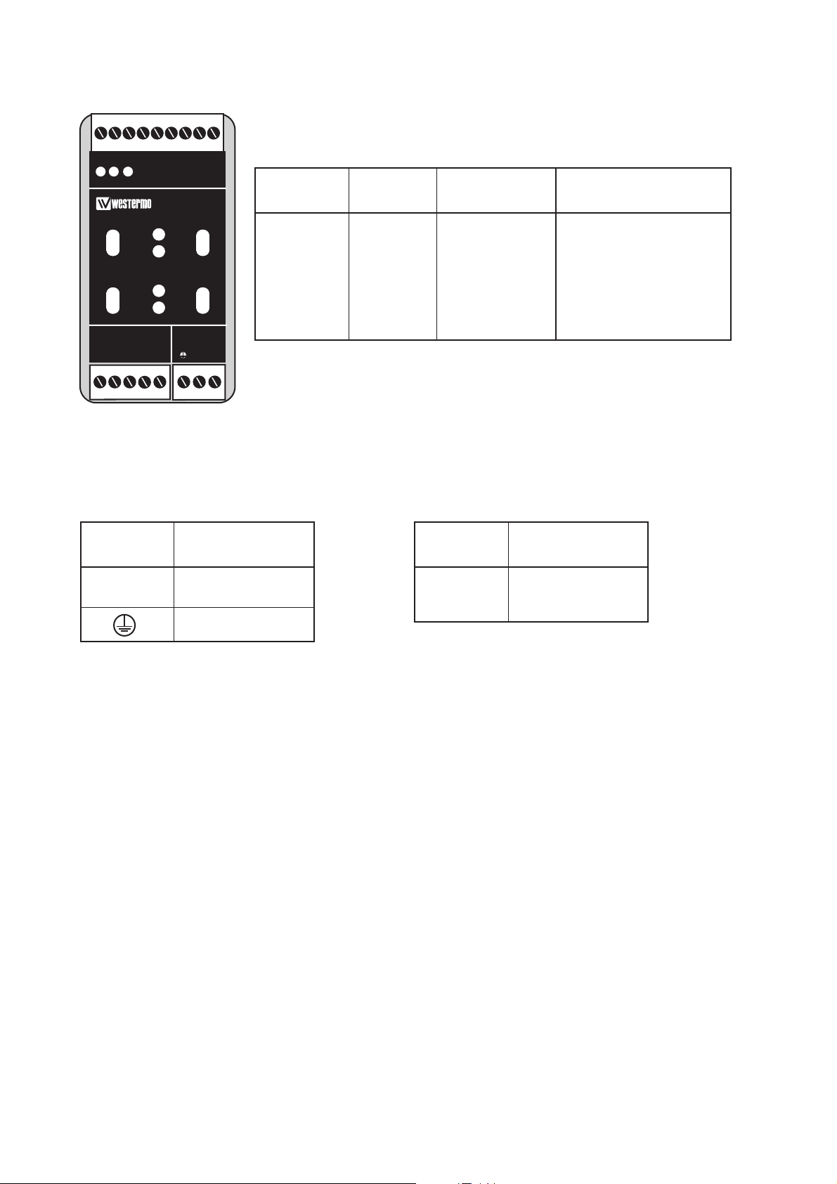
Specifications LD-63H
Transmission Asynchronous*, full/half duplex or simplex
Interface 1 EIA RS-232/ITU-T V.24
9-position detachable screw-terminal
Interface 2 4 ST-connectors, see table of power budget
Indicators Power, TD, RD, TX1, TX2, RX1, RX2
Data rates Up to 115,2 kbit/s
Temperature range 5–50°C, ambient temperature
Humidity 0–95% RH without condensation
Dimension 55x100x128 mm (WxHxD)
Weight 0.6 kg AC / 0.3 kg DC
Mounting On 35 mm DIN-rail
Power supply alternatives
Functional description LD-63H
LD-63H is developed for RS-232 multidrop communication via fibre-optic cables. The H-version
is developed for data and status transmission in a multidrop network. Transmission rates up to
115,2kbit/s and transmission distances up to 25km is possible.
The LD-63H consists of two F/O channels, each with its separate transmitter and receiver
(TX1, TX2, RX1 and RX2). On the front of the unit there are seven LED’s indicating the datatransmission on the channels. The fibre optic interface is transparent which means that data
received on RX1 is retransmitted on TX2 and data received on RX2 on TX1.
The number of LD-63’s that can be connected in series is limited, see chart on page 4.
* Synchronous protocols can be transmitted under certain circumstances.
See ”selection of bits” page 4.
Model description
LD-63H LD-63H LD-63H LD-63H LD-63H
AC 115V AC DC 36–55V DC 110V DC
Power supply 230V AC 115V AC 24V DC 48V DC 110V DC/80V AC
+15/–10% +15/–10% +50/–50% +15/–25% +10/–10%
Frequency 48–62Hz 48–62Hz – – –/48–62Hz
Fuse, F2 100mA S 100mA S 1.6A S 1.6A S 1A T/1A T
5x20 mm 5x20 mm 5x20 mm 5x20 mm –/–
Littelfuse Littelfuse Littelfuse Littelfuse Wickmann
Power consumption 25 mA 50 mA 3W 3W 30 mA
Overvoltage
protection 430V 220V – – 430V
Isolation 1 500V 1 500V 500V 500V 3 750V
RMS
Page 3

36072-2281
Transmitted power channel 1
Low
S2
High
S2
Transmitted power channel 2
Low
S3: 2–4 is not used
S3
High
S3
ON
1234
ON
1234
ON
12345
ON
12345
Factory settings
S1
ON
123456789
S3
ON
1234
S2
ON
12345
Status signal
Disabled
S1
ON
123456789
Enabled
S1
ON
123456789
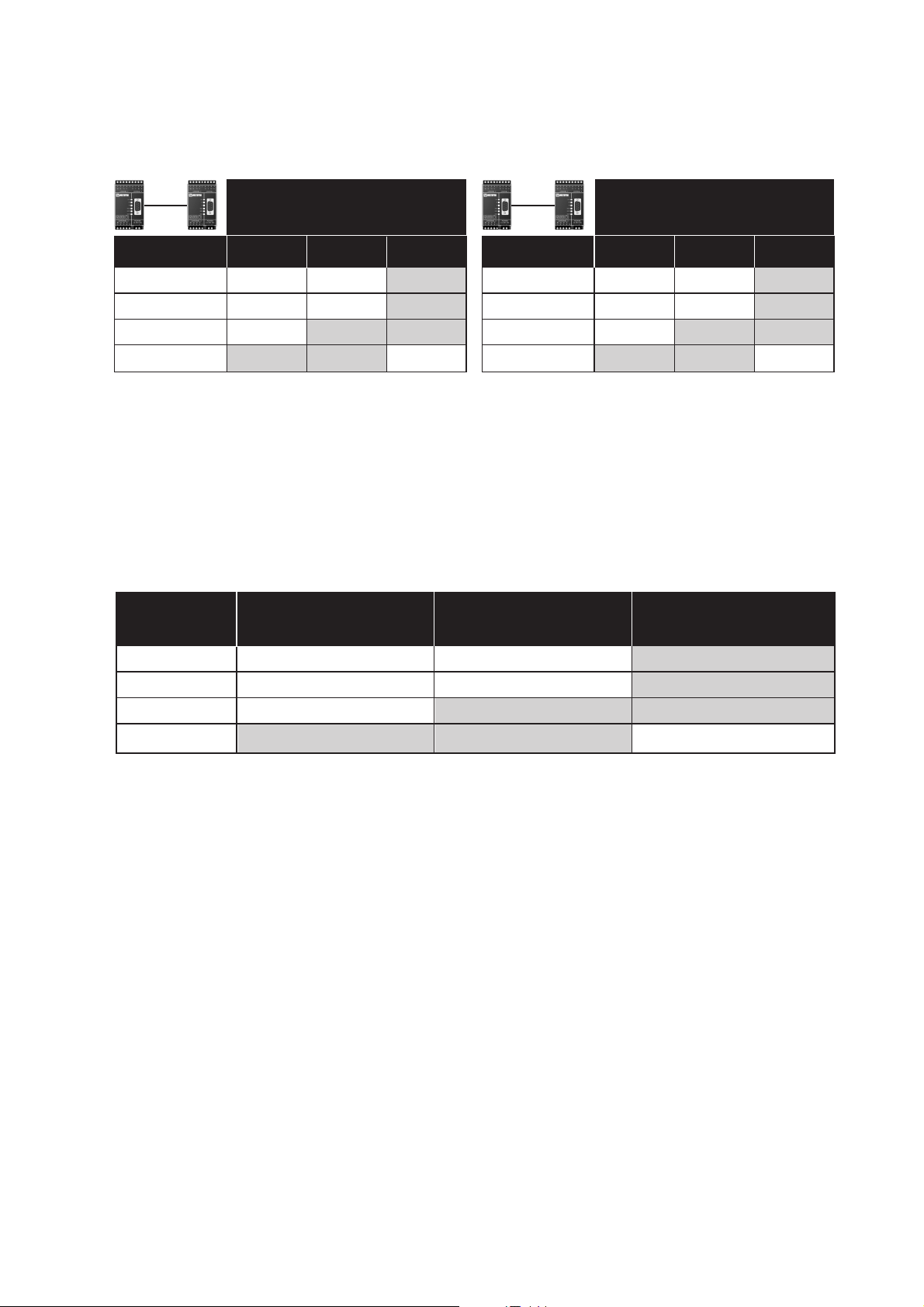
Switch settings LD-63H
Status signal disabled implies an active CTS to
the connected equipment.
For reliable function the status signal must be
at a stable state during data transmission.
S3:4-1
S1:1-9
S2:1-5
1
2
3
4
5
6
7
8
9
Page 4
4 6072-2281
Connections LD-63H
Power connection
LD-63H DC
(2-position screw-terminal)
Terminal connection (DCE)
(RS-232-C/V.24, 9-position screw-terminal)
Direction Screw CCITT V.24 Description
no. Description
I 8 103 TD/Transmitted Data
O 7 104 RD/Received Data
I 6 105 RTS/Request to send
O 5 106 CTS/Clear to send
– 1 & 9 102 SG/Signal Ground
I = Input O = Output on LD-63H
Connection Power
no. supply
1 – Voltage
2 + Voltage
Power connection
LD-63H AC
(3-position screw-terminal)
Connection Power
no. supply
L 115**/230V
N AC power
PE/ Protective Earth
** LD-63H 115V
LEDs for indication on LD-63H
• PWR: Indicates that the converter has power.
• TD: Indicates that the converter is receiving data on RS-232/V.24 side.
• RD: Indicates that the converter is sending data on RS-232/V.24 side.
• Rx1: Indicates received data on fiber channel 1.
• Rx2: Indicates received data on fiber channel 2.
• Tx1: Indicates that the converter is sending data on fiber channel 1 from RS-232/V.24 side.
• Tx2: Indicates that the converter is sending data on fiber channel 2 from RS-232/V.24 side.
TD RDPWR
LD-63
Rx1
Rx2
Tx1
Tx2
RS-422/485 POWER
R+
R- T+ T-
12345 LN
Page 5
56072-2281
50/125 µm 3.0 dB/km 1.0 dB/km
62.5/125 µm 3.5 dB/km 1.2 dB/km
100/140 µm 4.0 dB/km
9/125 µm 0.5 dB/km
Fibre
Attenuation
at 820 nm
Attenuation
at 1300 nm
Attenuation
at single mode (1300 nm)
Attenuation in fibre cable
The values below can differ depending on quality and manufacturer of the fibre-optic
cable.
Attenuation in connectors Attenuation in splice
0.2–0.4 dB Fusion 0.1 dB
Mechanical 0.2 dB
50/125 16.6 dB 14.6 dB
62.5/125 18.6 dB 15.1 dB
100/140 25.9 dB
9/125 12.3 dB
50/125 10.7 dB 8.1 dB
62.5/125 14.5 dB 11.6 dB
100/140 20.6 dB
9/125 6.3 dB
Unit
820 nm 1300 nm single mode
Unit
820 nm 1300 nm single mode
Min. budget Typ. budget
Power budget
”Min. budget” states the minimum guaranteed power budget. Experience shows however that the
typical value is in the range of the indicated ”Typ. budget”.
Fibre
Fibre
Page 6
6 6072-2281
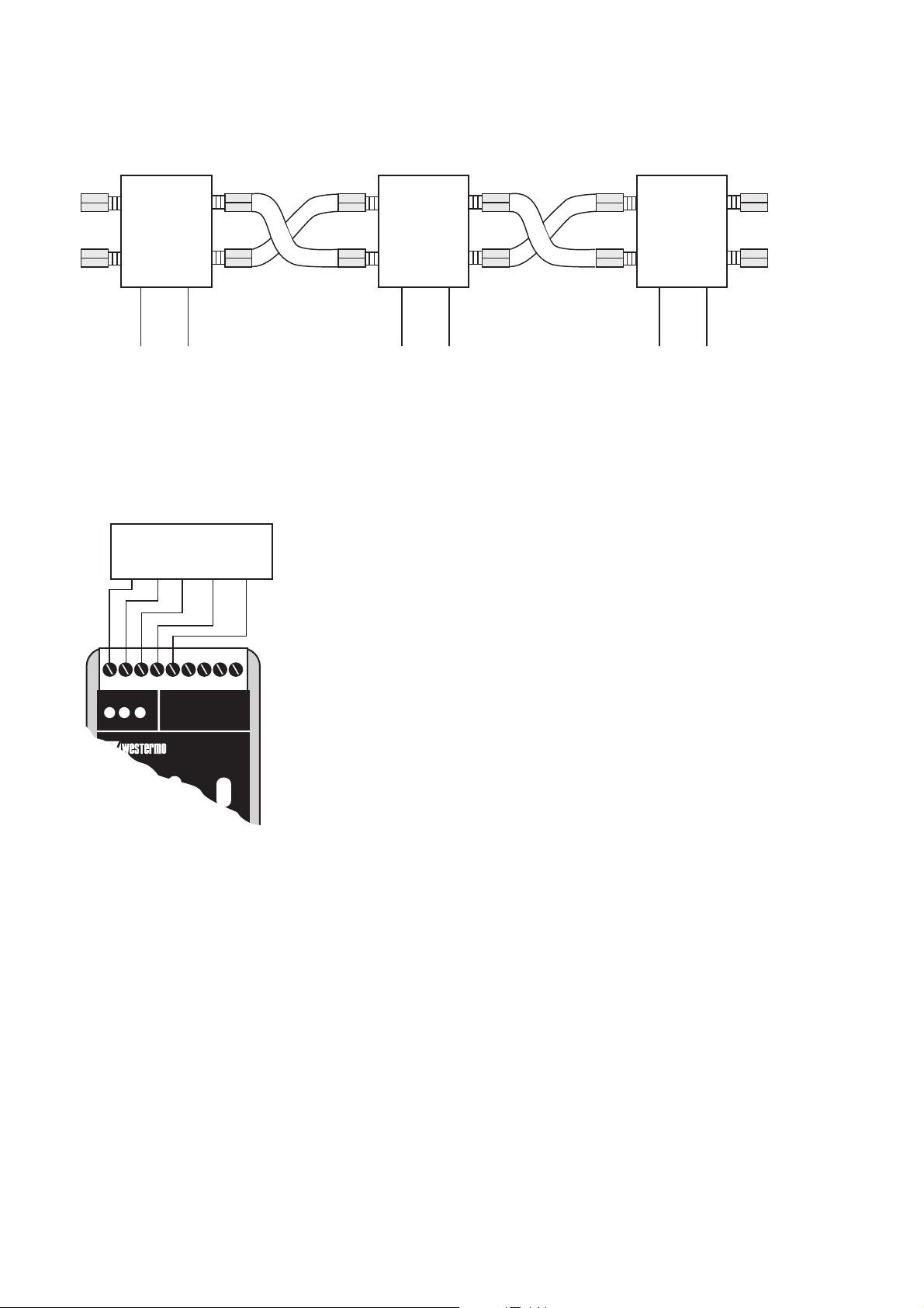
RS-232/V.24
How to connect
Connection of RS-232/V.24
Fibre optic connection
LD-63H
RX1 RX2
TX2
TX1
RX1 RX2
TX2
TX1
LD-63H LD-63H
RS-232/V.24 RS-232/V.24
RX1 RX2
TX2
TX1
SG TD RD RTS CTS
RS-232/V.24
equipment
LD-64
TD RD C EPWR
Ch1
OPTO LINK MONITOR
Rx1
Rx2
CE
Ch2
Page 7

Page 8
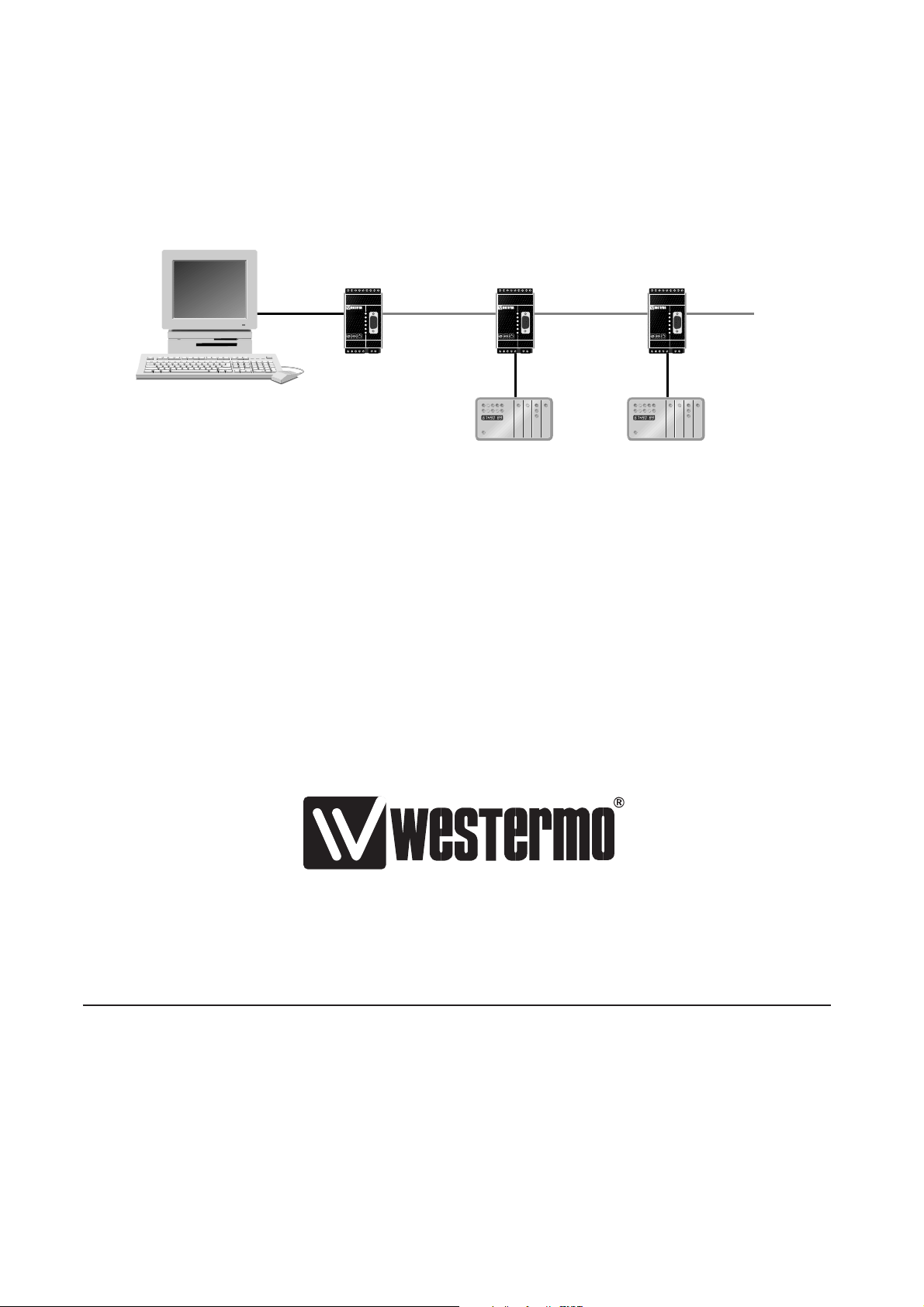
Application example
RS-232
MD-62H LD-63H LD-63H
RS-232 RS-232
Fibre Fibre
6072-2281 01.09 Mälartryck AB, Eskilstuna, Sweden
Westermo Teleindustri AB • SE-640 40 Stora Sundby, Sweden
Phone +46 16 42 80 00 Fax +46 16 42 80 01
E-mail: info@westermo.se • Westermo Web site: www.westermo.se
Westermo Teleindustri AB have distributors in several
countries, contact us for further information.
Westermo Data Communications Ltd
Unit 14 Talisman Business Centre • Duncan Road
Park Gate, Southampton • SO31 7GA
Phone: +44(0)1489 580 585 • Fax.:+44(0)1489 580586
E-Mail: sales@westermo.co.uk • Web: www.westermo.co.uk
Westermo Data Communications GmbH
Goethestraße 67, 68753 Waghäusel
Tel.: +49(0)7254-95400-0 • Fax.:+49(0)7254-95400-9
E-Mail: info@westermo.de • Web: www.westermo.de
Westermo Data Communications S.A.R.L.
9 Chemin de Chilly 91160 CHAMPLAN
Tél : +33 1 69 10 21 00 • Fax : +33 1 69 10 21 01
E-mail : infos@westermo.fr • Site WEB: www.westermo.fr
Subsidiaries
123456789123456789
R+ R- T+ T- T+ T- R+ R-
CHANNEL 3
CHANNEL 4
PWR
RD
TD
DCD2
DCD3
DCD4
CHANNEL 2 POWER
123456789123456789
R+ R- T+ T- T+ T- R+ R-
CHANNEL 3
CHANNEL 4
PWR
RD
TD
DCD2
DCD3
DCD4
CHANNEL 2 POWER
123456789123456789
R+ R- T+ T- T+ T- R+ R-
CHANNEL 3
PWR
RD
TD
DCD2
DCD3
DCD4
CHANNEL 2 POWER
 Loading...