

WERMA StockSAVER Instruction Manual

StockSAVER
Software version 2.1
WERMA Signaltechnik GmbH + Co. KG
D-78604 Rietheim-Weilheim
Telephone: +49 (0)7424 / 9557-222
Fax: +49 (0)7424 / 9557-44
support@werma.com
www.werma.com
310.865.005 0317_AA

Table of contents
StockSAVER manual - Software version 2.1
2
Table of contents
1 Introduction ........................................................................................................................................ 5
1.1 Target groups ..................................................................................................................................... 5
2 Safety information ............................................................................................................................. 6
2.1 Proper use ........................................................................................................................................... 6
2.2 General safety instructions .............................................................................................................. 6
3 Product description .......................................................................................................................... 7
3.1 Overview of hardware components ............................................................................................ 8
3.2 SensorBox ............................................................................................................................................ 9
3.3 Overview: SmartBox ....................................................................................................................... 10
3.3.1 SmartBox controls ...................................................................................................................... 10
3.3.2 SmartBox display messages ..................................................................................................... 10
3.3.3 SmartBox connections .............................................................................................................. 11
3.4 Overview: Transceiver .................................................................................................................... 12
3.5 Barcode scanner (optional) ......................................................................................................... 13
3.6 Software module overview ........................................................................................................... 14
4 Getting started: Overview of installation and commissioning ............................................... 15
5 Attaching the hardware to racks ................................................................................................ 16
5.1 Preparation ...................................................................................................................................... 16
5.1.1 Unpack devices and components ........................................................................................ 16
5.2 Installing the hardware .................................................................................................................. 17
5.2.1 Installing the sensors .................................................................................................................. 17
5.3 Installing a SensorBox ..................................................................................................................... 18
5.3.1 Wiring a SensorBox..................................................................................................................... 18
5.3.2 Wiring the bus ............................................................................................................................. 19
5.4 Installing the SmartBox ................................................................................................................... 20
5.5 Installing a Transceiver ................................................................................................................... 21
5.6 Functional test ................................................................................................................................. 22
5.7 Installing the software .................................................................................................................... 23
5.7.1 System requirements ................................................................................................................. 23
5.7.2 Network stability and security ................................................................................................. 25
5.7.3 Overview: System architecture ............................................................................................... 25
5.7.4 Installing WERMA StockSAVER ................................................................................................. 27
5.7.5 Advanced Server Installation .................................................................................................. 29
5.7.6 Installing a client on other PCs ................................................................................................ 30
5.8 Commissioning the hardware ...................................................................................................... 31
5.8.1 Wiring the racks .......................................................................................................................... 31
5.8.2 Connecting and configuring the Transceiver...................................................................... 31
5.8.3 Connecting and configuring the SmartBox ......................................................................... 33
5.8.4 Connect the SmartBox and Transceiver to the rack .......................................................... 36

Table of contents
StockSAVER manual - Software version 2.1
3
5.8.5 Configuring racks....................................................................................................................... 37
5.8.6 Configuring the bus cabling .................................................................................................... 38
6 System operation ............................................................................................................................ 39
6.1 Overview: Control Station ............................................................................................................. 39
6.2 Overview: Material Requirement List .......................................................................................... 40
6.2.1 Material Requirement List columns: Displaying a Single Location ................................... 40
6.2.2 Material Requirement List columns: Displaying Total Material .......................................... 41
6.3 Overview: Material Master ............................................................................................................ 42
6.4 Analysis .............................................................................................................................................. 43
6.4.1 Analysis and export function ................................................................................................... 47
6.4.2 Export to Excel ............................................................................................................................ 48
6.5 Configuring racks ............................................................................................................................ 49
6.6 Changing Settings .......................................................................................................................... 50
6.6.1 General........................................................................................................................................ 50
6.6.2 Views ............................................................................................................................................ 51
6.6.3 Devices ........................................................................................................................................ 52
6.6.4 Location ...................................................................................................................................... 52
6.6.5 Reports ......................................................................................................................................... 53
6.6.6 Functions ..................................................................................................................................... 53
6.7 System expansion ........................................................................................................................... 54
6.7.1 Changing the bus wiring .......................................................................................................... 54
6.8 Routing .............................................................................................................................................. 54
6.9 Connections ..................................................................................................................................... 56
6.10 CSV Interface ................................................................................................................................... 56
6.10.1 Exporting material movements to CSV ................................................................................. 56
6.10.2 Importing Material Master data from CSV ........................................................................... 59
6.10.3 Importing Location assignments from CSV ........................................................................... 61
6.11 XML interface ................................................................................................................................... 62
6.11.1 Configuring the Interface Service .......................................................................................... 62
6.11.2 XML import of Material Master data sets .............................................................................. 67
6.11.3 XML export of Material movements ........................................................................................... 70
6.11.4 Journal .............................................................................................................................................. 74
7 Software administration ................................................................................................................. 75
7.1 Uninstalling the software ................................................................................................................ 75
7.2 Installing updates ............................................................................................................................ 75
7.3 Unsupervised client installation .................................................................................................... 75
7.4 Administration console: Managing data ................................................................................... 75
7.4.1 Option: Manage data via the command line .................................................................... 76
7.5 Adjusting and synchronising the time ......................................................................................... 76
7.6 Alter the Server Service/database connection ........................................................................ 77
7.7 Firmware update ............................................................................................................................ 77
8 Troubleshooting ............................................................................................................................... 78

Table of contents
StockSAVER manual - Software version 2.1
4
8.1 Transceiver problems ..................................................................................................................... 78
8.2 SmartBox problems ......................................................................................................................... 79
8.3 SensorBox problems ........................................................................................................................ 79
8.4 Sensor problems .............................................................................................................................. 80
8.5 Software setup problems ............................................................................................................... 80
8.6 Software problems .......................................................................................................................... 80
8.7 Information on log files ................................................................................................................... 83
8.7.1 Request log files from the software ........................................................................................ 83
8.7.2 Activating detailed logging .................................................................................................... 83
8.7.3 Log file parameters ................................................................................................................... 83
9 Technical data ................................................................................................................................ 84
9.1 General ............................................................................................................................................. 84
9.2 Ratings ............................................................................................................................................... 84
9.3 Wireless .............................................................................................................................................. 85

Introduction
StockSAVER manual - Software version 2.1
5
1 Introduction
These instructions provide all the information required to operate the WERMA StockSAVER. The
instructions must be read by all persons assigned to work on this system.
1.1 Target groups
This manual is intended for:
− Production logisticians who will be working with the system.
− IT professionals who will be performing software configuration.
− Professional electricians who will be assembling the hardware components.

Safety information
StockSAVER manual - Software version 2.1
6
2 Safety information
2.1 Proper use
The device must be assembled and wired in accordance with the assembly instructions by a
professional electrician. Only use the components supplied.
The software must be configured by an IT professional.
The system must be commissioned and operated in accordance with this manual to ensure
the safety of operating personnel and protect the StockSAVER system from inc orre ct
operation.
Read the operating instructions carefully before assembly and commissioning. Keep these
operating instructions in a convenient place for future reference.
Special arrangements must be made if your production logistics processes involve returning
opened bins to storage from the withdrawal side to avoid irregularities in material requisition
and analysis functions.
Data is processed exclusively by the StockSAVER software. The system does not support direct
read or write access to the database content or alterations to the database structures by
other software. WERMA reserves the right to optimise the software and connected database.
Updates can lead to alterations, replacements and deletions in the database. Unauthorised
alterations can affect the operation of the software or individual functions.
2.2 General safety instructions
− The system must only be connected by a professional electrician taking into account the
operating instructions and the guidelines as well as standards applicable in the area of
use.
− Maintenance tasks must be performed by a professional electrician with the system
disconnected from the power supply.
− The operator is solely responsible for adherence to local safety regulations, for monitoring
and control of the StockSAVER system and for the results achieved using the system. The
purchaser must test the software thoroughly for applicability in their specific situation
before beginning productive use. The purchaser is obliged to make suitable provisions for
the eventuality that the system does not work properly either entirely or in part (e.g. by
backing up data, documenting the use of the software, fault diagnostics, regular testing
of results, emergency planning). It is the purchaser's responsibility to ensure the viability of
the system's working environment.
− When not in use, keep the WERMA StockSAVER system in the original packaging to ensure
optimum protection against damage.
− Modification of the system or improper use renders the guarantee void and invalidates
the manufacturer's responsibility.
− Usage that is not described in the manual is considered to be improper. The operator of
the product is liable for damage caused by improper use.

Product description
StockSAVER manual - Software version 2.1
7
3 Product description
The StockSAVER system serves as a signal point in the logistics chain and monitors fill levels of
commercially-available FIFO flow racks. Fill levels are communicated wirelessly and visualised
in the StockSAVER software based on the intelligent interaction of the system components.
Sensors mounted in the racks record the fill levels. This status information is collected by the
SensorBox and transmitted to the SmartBox using a bus system. The data is transmitted
wirelessly to the Transceiver and written to the database by the software.
Misplaced replenishments can also be promptly detected if an optional barcode scanner is
employed.
StockSAVER software provides a wide range of functions for optimising work processes using
FIFO flow racks and the production logistics process.
The system sensor, SmartBox and SensorBox components and the mounting materials have
been developed for installation in FIFO flow racks. The following rack types have been tested
for compatibility:
− SSI Schäfer KDR live carton storage racks
− Creform pipe racks, Ø 28 mm series
− Bito live storage racks, type 36-33250
− Bosch Rexroth XLEAN material supply racks
Compatibility with other rack types and mounting options must be established before
installation.
Product description
StockSAVER manual - Software version 2.1
8
Item
Components
Function
the SensorBox.
location. Forwards the data to the bus system.
SmartBox also warns about misplaced products.
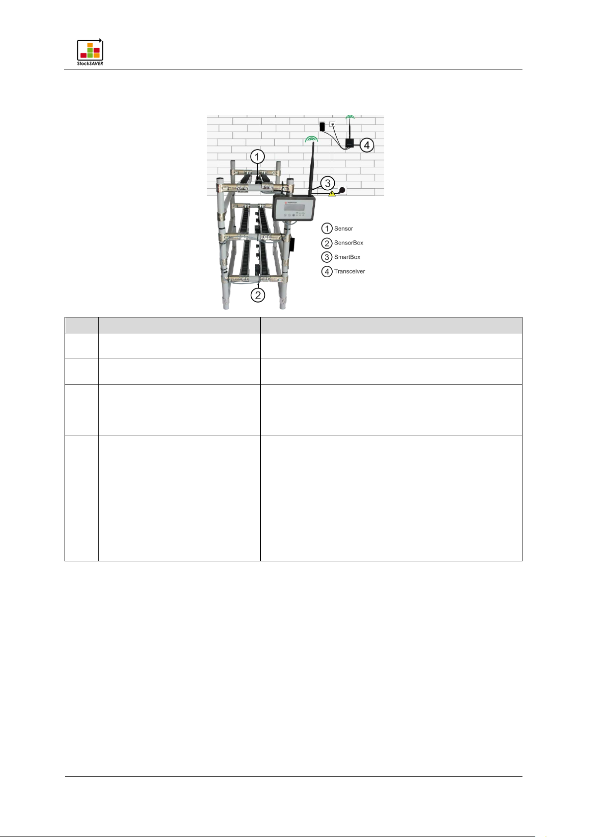
4
Transceiver
Receives statuses from up to 20 SmartBoxes.
range: 300 m (line-of-sight)
3.1 Overview of hardware components
1 Sensor Detects bins and forwards the status information to
2 SensorBox Receives the sensor status of up to 4 bins per
3 SmartBox Receives data from up to 50 SensorBoxes via the
bus system and transmits it to the Transceiver.
If the optional barcode scanner is used, the
Transfers data to the Server Service (Software). The
data is then stored the database and displayed on
client PCs.
Up to 4 Transceivers may be connected to a
database.
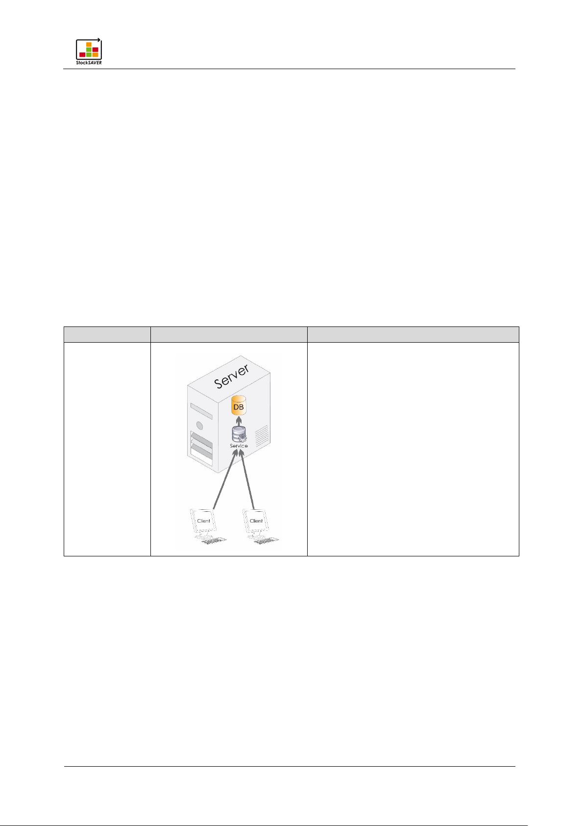
Power is supplied via the included mains plug-top
adapter. The Transceiver is connected to the
network via Ethernet cable. Maximum wireless
StockSAVER manual - Software version 2.1
9
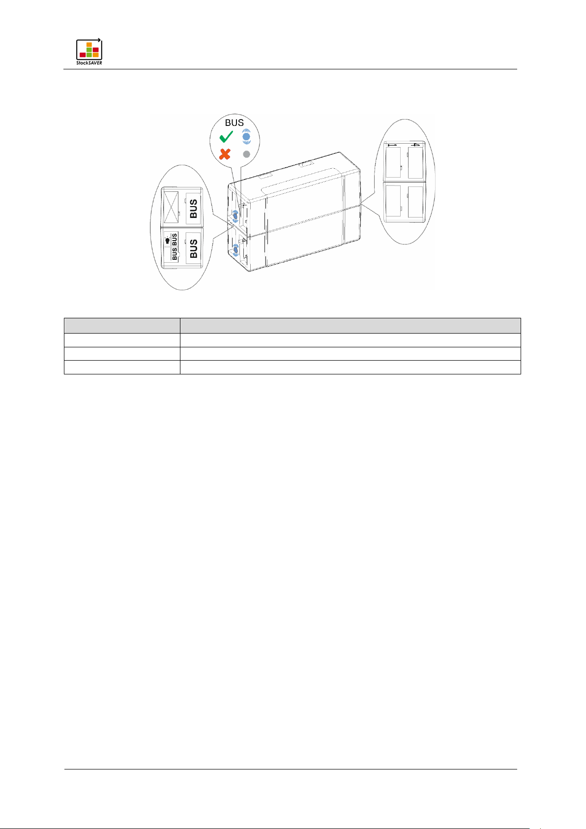
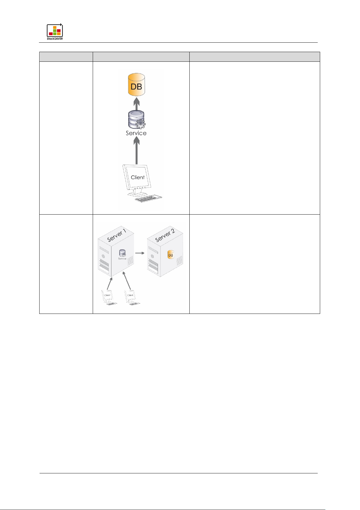
3.2 SensorBox
LED
Function
Bus LED flashes blue
Power supply present; bus connection interrupted
Bus LED off
No power supply and no bus connection
Bus LED steady blue
Power supply and bus connection present
Up to 4 sensors may be connected (see right)
Product description
StockSAVER manual - Software version 2.1
10
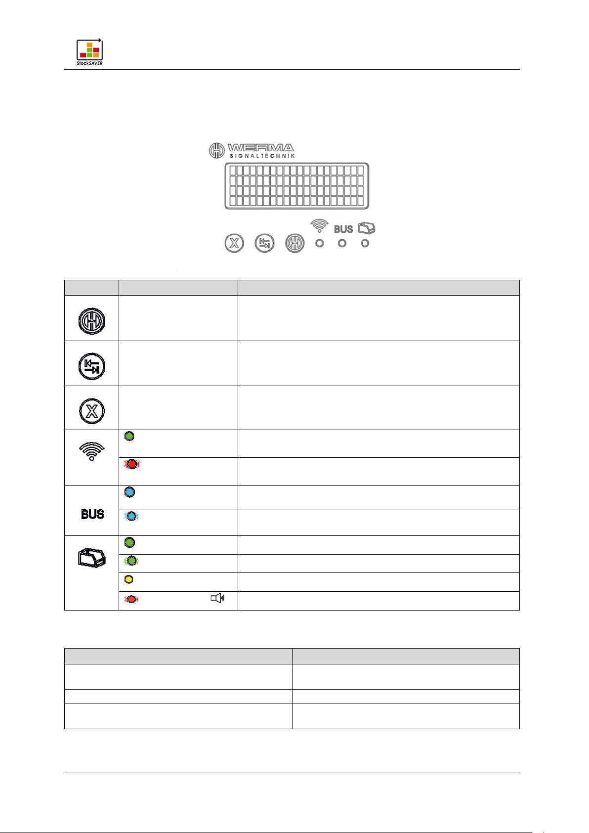
3.3 Overview: SmartBox
Icon
LED
Function
Hold down for approx. 5 s to access the volume menu.
Wireless connection present
Wireless connection not present
Bus connected to following SensorBox
Bus not connected to following SensorBox or no
SensorBox connected
Known material
Message
Cause
been initialised and is ready for operation.
Initialisation…
SmartBox is being initialised.
present.
3.3.1 SmartBox controls
Product description
Close the volume menu.
Increase the volume when in the volume menu
Reduce the volume when in the volume menu
If misplaced products are detected: Acknowledge
On (Green)
Flashes (Red)
On
Flashes
On (Green)
Flashes (Green)
On (Yellow) Unknown material
Flashes (Red)+ Misplaced Replenishment
correction of misplaced products
Database query running
3.3.2 SmartBox display messages
Ready... The system has a wireless connection, has
No connection… No wireless connection to the Transceiver is
Product description
StockSAVER manual - Software version 2.1
11
Message
Cause
Connecting and configuring a SmartBox.
displayed.
defined structure.
Material Master data.
SmartBox.
Error: SmartBox not initialised
SmartBox is not initialised.
Error: SensorBox full
Location has maximal load.
Error: Unknown reason
Unknown error. Repeat the process.
correctly.
Placement error
A product has been stored without first being
scanned.
Item
Connector
Device
Comment
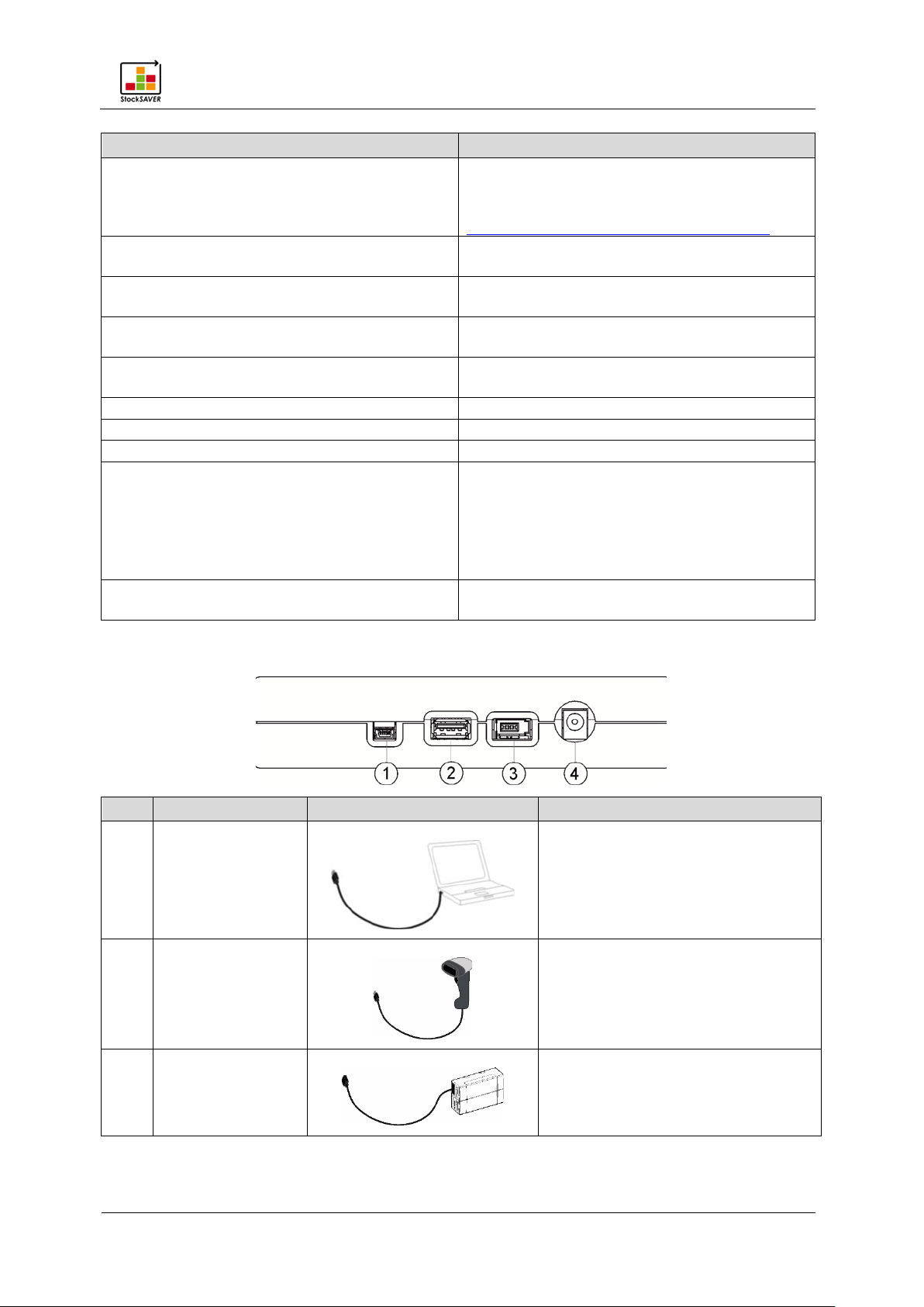
2
USB
Only for human interface devices
Not configured… SmartBox is not configured and cannot be
detected by the softw a re . S olutio n :
Configure the SmartBox via USB. See
Shelf Location is being detected and will be
Material not readable The Part Number does not correspond to the
Error: Material unknown The Part Number is not defined in the
Error: Material not available The Part Number is not available in this
Placement error Replenishment placed in the wrong Location
Solution:
Remove the material from the Location.
Press the X button.
Rescan the bins and place them in stock
3.3.3 SmartBox connections
1 Mini USB
3 BUS
Only required for configuration and
firmware updates
Connection to first SensorBox
Product description
StockSAVER manual - Software version 2.1
12
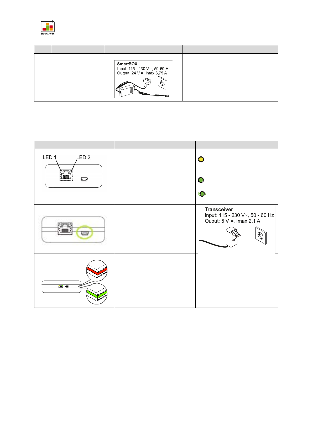
Item
Connector
Device
Comment
Components
Connector
LED
LED1
activity
Power supply/
Wireless connection
Red if no wireless connection
4 Power supply
3.4 Overview: Transceiver
Network
Input: 115-230 V
Output: 24 V
On (yellow) when
connected to the software
LED2
On (green) when
connected to the network
Flashes during network
commissioning hardware
is established with SmartBox
Green if wireless connection is
established with SmartBox
Product description
StockSAVER manual - Software version 2.1
13
Connector
Manufacturer
Type
RFID USB reader
I-keys RFID USB reader
RFID
Wired scanner
Motorola LS2208
Barcode
Wired scanner
Honeywell 1900
Barcode/2D
Wireless scanner
Motorola/Symbol LI4278
Barcode
Integrated scanner
Honeywell Quantum MS3580
Barcode
Bluetooth scanner
DataLogic
QuickScan QBT2131
Barcode
3.5 Barcode scanner (optional)
The optional barcode scanner enables the "SmartBox with identification" to be used to
identify and log misplaced material.
The scanner must be configured so that it is detected as a USB HID and the string ends with a
Carriage Return (0x0D) or with a Line Feed (0x0A). The keyboard layout language must also
be set to English (or German as required). Details of scanner configuration can be found in
the scanner instructions.
The scanner is not included and cannot be purchased from WERMA Signaltechnik. We have
tested the following barcode scanners for compatibility. Please contact us for the latest
overview.
Please contact your scanner supplier with any queries concerning barcode scanner
configuration. In some cases, it may not be possible to guarantee correct function with other
devices.
Scanning barcodes
1. Scan the barcode on the bin. The correct location is displayed on the SmartBox and the
green LED is activated on the corresponding SensorBox.
2. Place the bin on the correct location. The SmartBox will beep once.
3. If the bin is stored incorrectly, the SmartBox beeps several times. The system is blocked for
further stock placement.
4. Remove the misplaced product from the rack and then press X on the SmartBox to
acknowledge the misplaced product.
The last procedure is undone and the system becomes available for further stock
placement.
Product description
StockSAVER manual - Software version 2.1
14
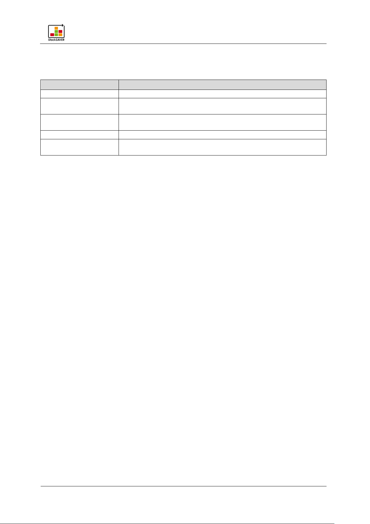
Software modules
Description
Control Station
Displays requirements and errors from the racks.
Material Requirement
List
Displays current requirements and data related the stored
materials.
Material Master data
Users create the materials in use individually, import them as CSV
files, edit materials or delete materials.
Analysis
Statuses can be evaluated or exported in a different format.
software
3.6 Software module overview
The StockSAVER software is divided into modules. The modules are:
Configuration Configuration of the hardware and rack representation in the

Getting started: Overview of installation and commissioning
StockSAVER manual - Software version 2.1
15
4 Getting started: Overview of installation and commissioning
Before you can begin working with your StockSAVER, you must first install the devices and
software and configure the system using wireless connections and USB.
1. Attaching the hardware to racks.
2. Install the software.
− Install the server.
− Install the client.
3. Commission hardware using the commissioning wizard
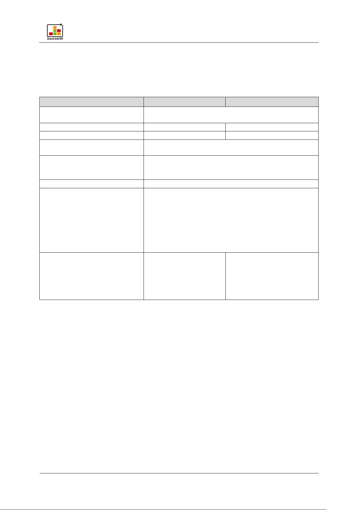
− Configure the Transceiver.
− Configure the SmartBox.
− Connect the devices to the rack.
4. Configure the rack in the software
.
:
StockSAVER manual - Software version 2.1
16
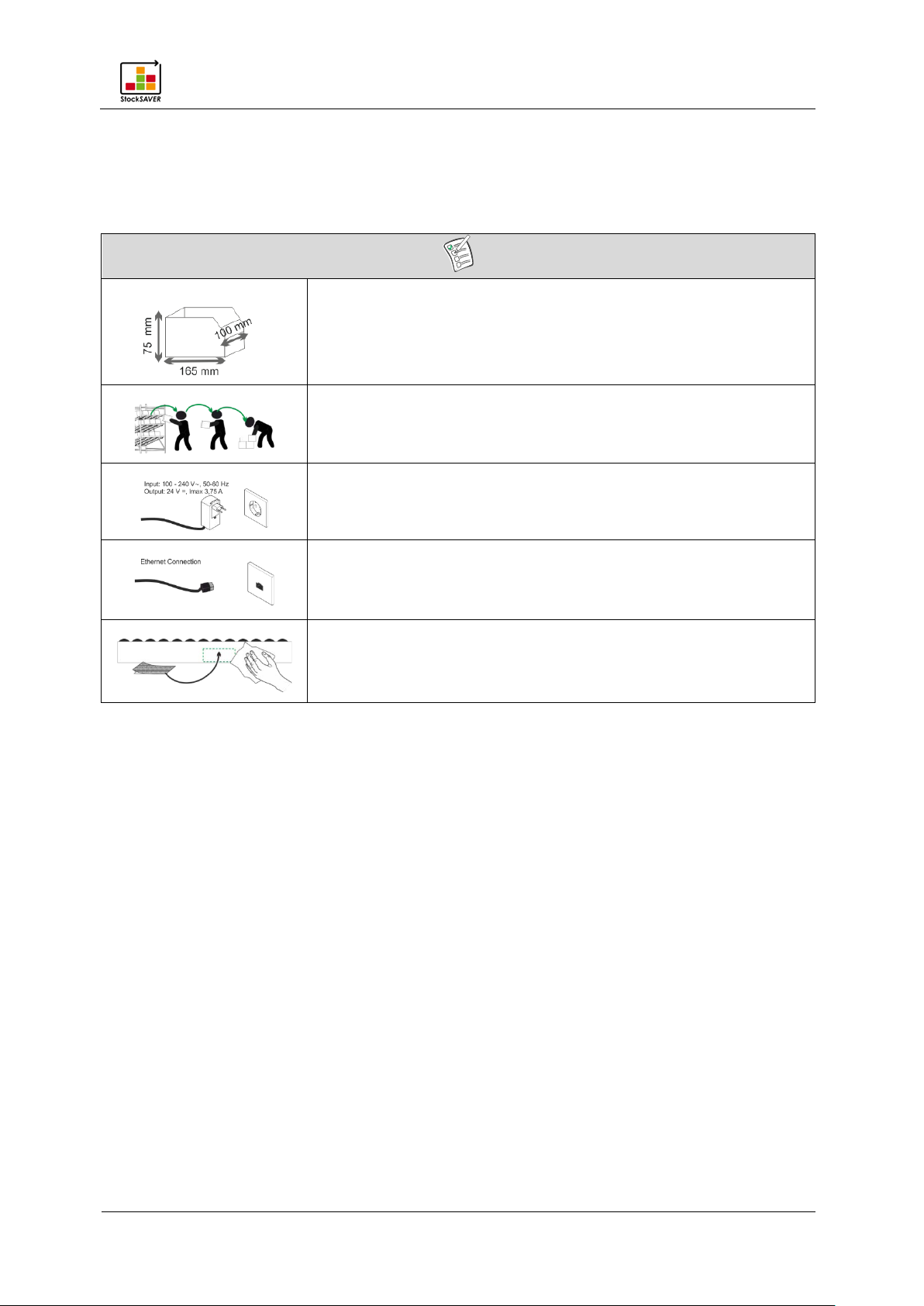
5 Attaching the hardware to racks
Note the minimum bin dimensions.
Remove all bins from the rack.
A power socket must be available nearby.
An Ethernet connection must be available.
Clean the rack using a cloth and a mild cleaning agent if
5.1 Preparation
Attaching the hardware to racks
necessary. Ensure it is free of grease or dust.
5.1.1 Unpack devices and components
1. Unpack the products and check for damage.
2. If damaged items are found, please inform WERMA Signaltechnik or the forwarding
agent.
3. Check the delivery against your order for:
− Delivered quantity
− Type and version of device according to type plate
− Accessories
− Quick guide
Attaching the hardware to racks
StockSAVER manual - Software version 2.1
17
5.2 Installing the hardware
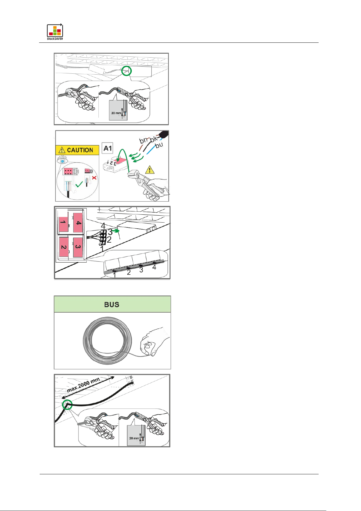
The following tools are additionally required to install the hardware:
− Parallel action crimping pliers
− Stripping tool for the sensor cable: 3.30 mm - 4.40 mm Ø
− Stripping tool for the bus cable: 4.40 mm - 7 mm Ø
These tools are available as a set; part number 865 000 29
Tip: Installing the components can be simplified by removing the shelving rails from the rack, if
the rack structure allows.
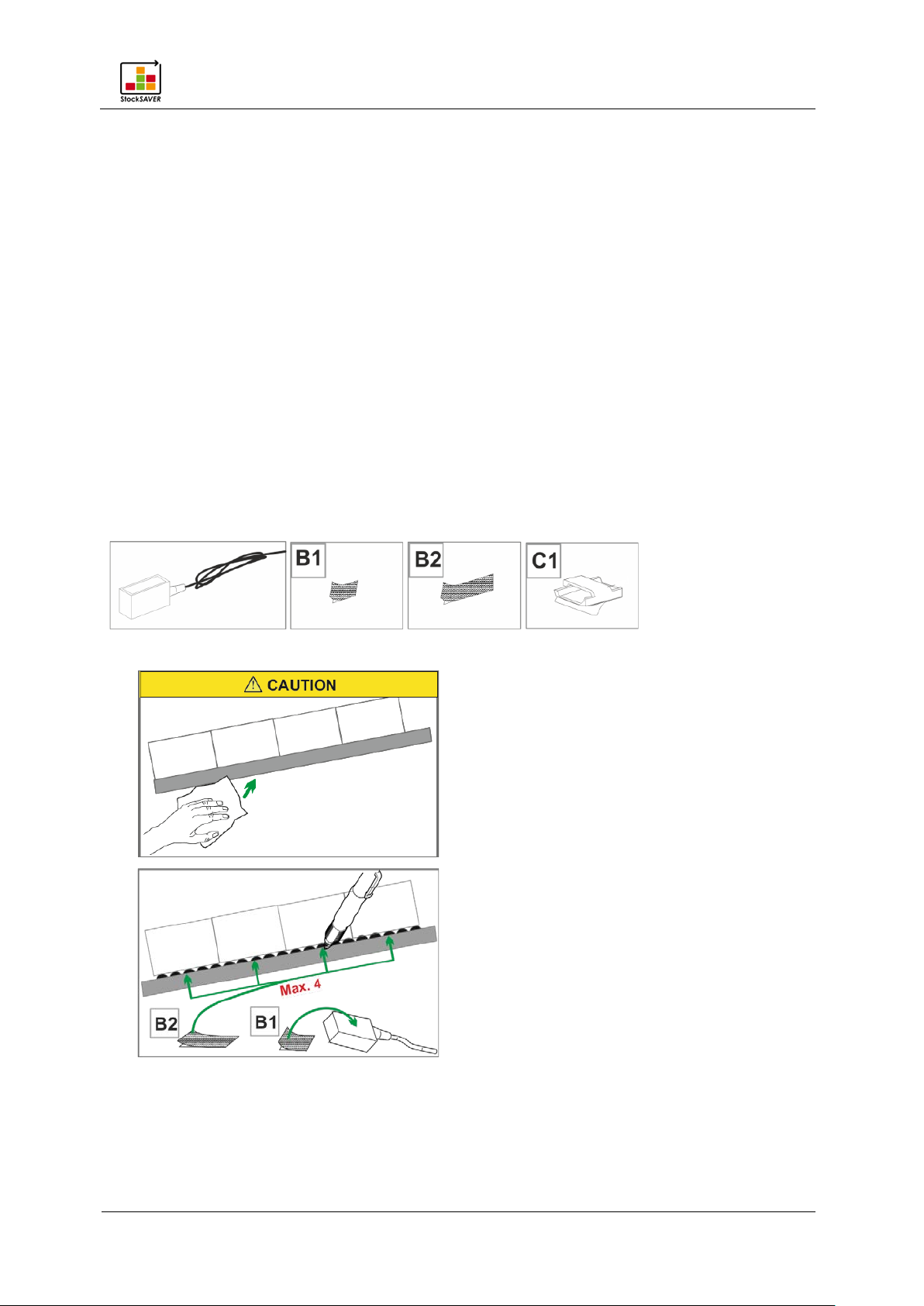
5.2.1 Installing the sensors
Tip: If a uniform bin size is used, we recommend pre-assembling the sensors (Installing the
cable and plug) outside the rack before actual assembly.
Required components
Procedure
1.
2.
Attaching the hardware to racks
StockSAVER manual - Software version 2.1
18
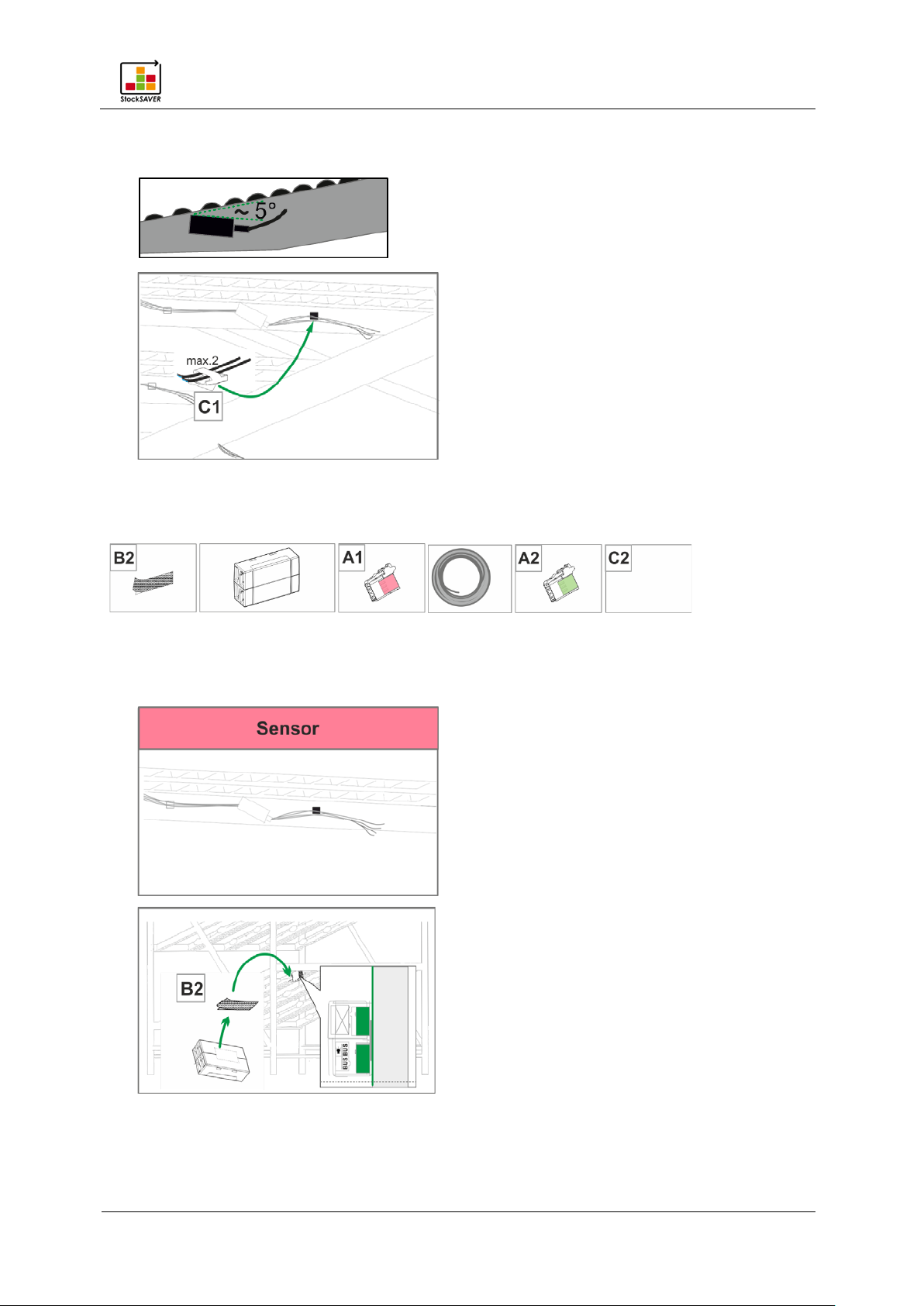
3. Attach the sensors tilted at an angle of 5° to prevent malfunction caused by reflective
surfaces. Clean sensors if they become heavily soiled during operation.
4.
5.3 Installing a SensorBox
Required components
5.3.1 Wiring a SensorBox
Leave sufficient room (approx. 10 cm) between SensorBoxes and the rack crossbeam to
allow space for the bus wiring.
1.
2.
StockSAVER manual - Software version 2.1
19
3.
4.
Attaching the hardware to racks
5.
5.3.2 Wiring the bus
1.
2.

StockSAVER manual - Software version 2.1
20
3.
4.
Attaching the hardware to racks
5.
6.
5.4 Installing the SmartBox
Required components
StockSAVER manual - Software version 2.1
21
Procedure
1.
2.
Attaching the hardware to racks
3.
4.
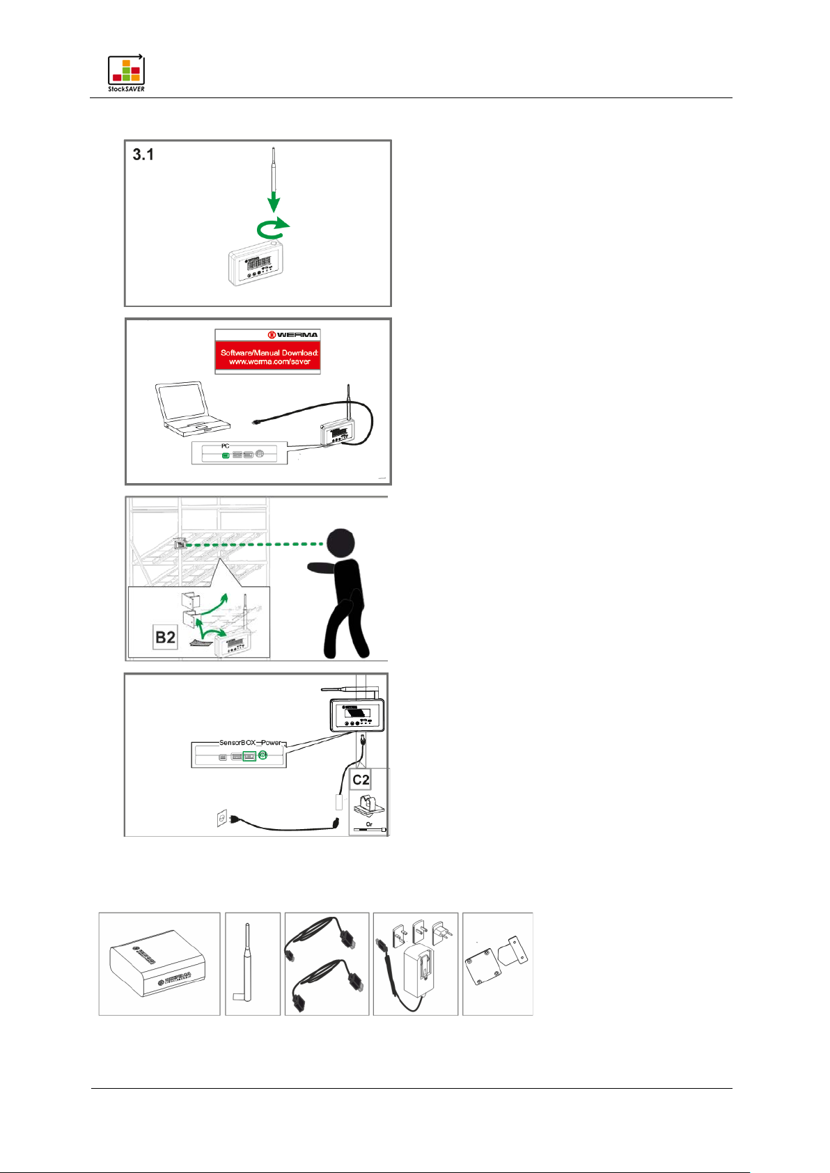
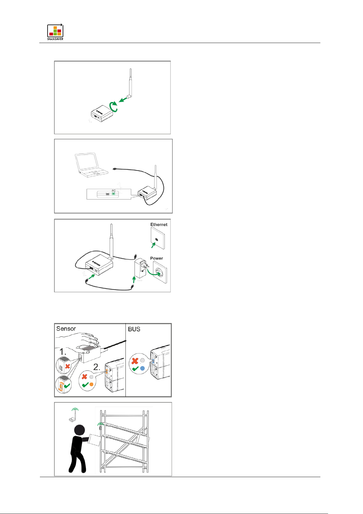
5.5 Installing a Transceiver
Required components
StockSAVER manual - Software version 2.1
22
Procedure
1.
2.
Attaching the hardware to racks
3.
5.6 Functional test
1.
2.

Attaching the hardware to racks
StockSAVER manual - Software version 2.1
23
5.7 Installing the software
5.7.1 System requirements
System requirements for the server PC and the client are different.
Server PC
The following software components are installed on the server PC:
− WERMA StockSAVER Server Service
− Microsoft SQL server 2014 Express local DB
− WERMA StockSAVER client (user interface)
− USB device driver for the hardware
− WERMA StockSAVER administration console
Attaching the hardware to racks
StockSAVER manual - Software version 2.1
24
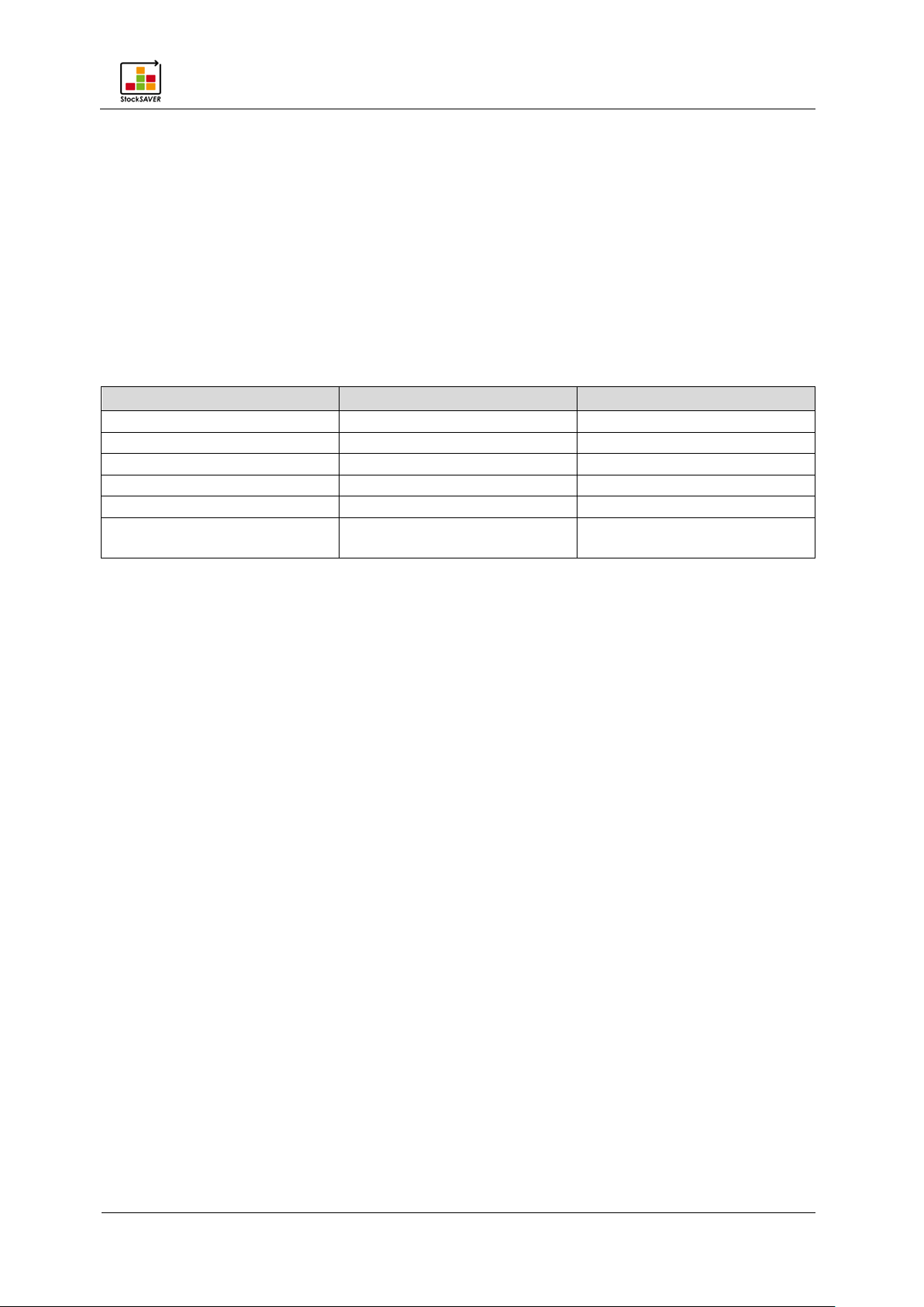
Name
Server PC
Client PC
Processor
Pentium-III-compatible processor or
fast dual-core processor recommended
Recommended RAM
3 GB
2 GB
Available hard drive memory
4.3 GB
1.8 GB
Configuration can be performed on the client PC
Monitor resolution
At least: 1280x1024
Text size scaling (DPI) up to 200% (192 DPI)
Microsoft .NET Framework 4.5.2
Automatically installed if not present
Supported operating systems
Windows 7 SP1
Windows server 2016
SP2
Client PCs
The following software components are installed on the client PC:
− WERMA StockSAVER client (user interface)
− USB device driver for the hardware
USB port Required for configuring the Transceiver and SmartBox.
Recommended from: 1920x1080
Windows 8
Windows 8.1
Windows 10
Windows server 2008 R2 SP1
Windows server 2012
Windows server 2012 R2
Supported SQL server Compatible from:
Microsoft SQL server 2008
SP4
Recommended:
Microsoft SQL server 2014
Note
− If not otherwise stated, both the 32-bit (x86) and 64-bit (x64) versions are supported.
− The latest service pack for Windows and Microsoft SQL server is supported.
− Windows server Core and Nano server installation is not supported.
− The Windows Remote Desktop Services server role is not supported on the server PC.
− Only the Express, Workgroup, Standard, Enterprise and Datacenter Microsoft SQL server
editions and the included Microsoft SQL server 2014 Express LocalDB are supported.
Attaching the hardware to racks
StockSAVER manual - Software version 2.1
25
Option
Visualisation
Comment
5.7.2 Network stability and security
We advise you to only operate WERMA StockSAVER in a reliable LAN environment (TCP/IP
network). An unstable or unsafe network can impair the function or performance of WERMA
StockSAVER.
5.7.3 Overview: System architecture
The following points on system architecture must be observed:
− During installation, the Server Service is installed on the server. When the server is started,
the service is automatically started and executed in the background.
− Only one Server Service can be used per database.
− Only one Server Service can be used per server.
− Recommendation: Use a static IP address for the server PC.
− Data will be written to the database as long as the database and the Server Service are
started on the server. The software does not have to be running on the client PC to do so.
System architecture options
Standard
Install the Server Service and the
database on a server.
Install the client application on a
workstation PC.
Attaching the hardware to racks
StockSAVER manual - Software version 2.1
26
Option
Visualisation
Comment
Option A
Option B
Install the Server Service, client and
database on a workstation PC.
Not recommended during productive
operation.
Install the Server Service and database on
two different servers. A separate SQL
Server, e.g. SQL Server Express, must be
installed beforehand.
Install the client application on a
workstation PC.
 Loading...