

Page 1
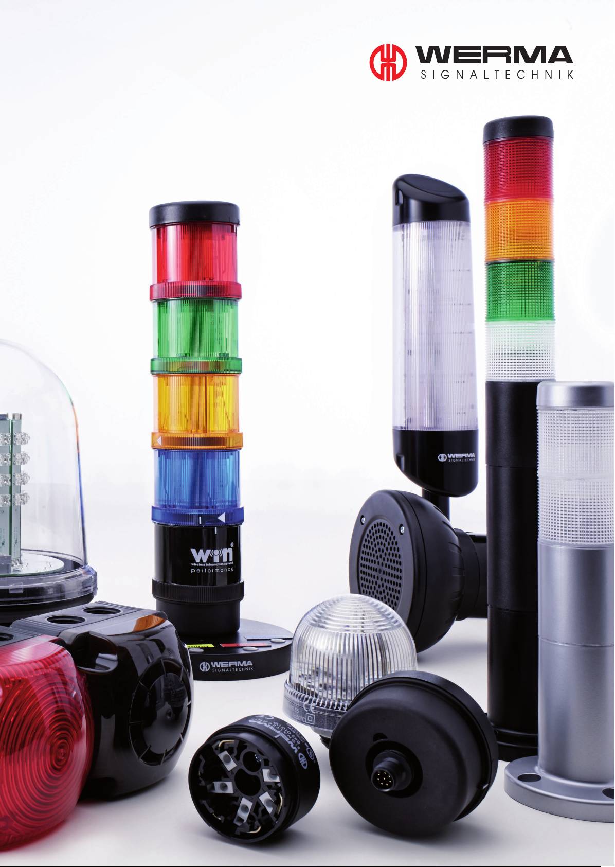
Catalogue
2015/ 2016
Page 2

Catalogue 2015/16
Page 3

About WERMA
We make sure you are seen and heard
WERMA Signaltechnik is one of the world‘s leading companies for optical and audible
signal devices. The international company located in South West Germany sets the tone
technologically with its many state-of-the-art innovations.
Our signal devices make working environments safe and processes effi cient - on machines,
in factory halls or in the building services industry. With a broad line of over 3,500 products,
WERMA offers solutions for an extremely wide range of signalling applications.
We are there where you need us
With our own subsidiaries in many European countries as well as in China and the USA and
a tightly woven network of international sales partners we ensure outstanding worldwide
on-site support. Our customers benefi t from exemplary service with fast, on-time delivery of
all products and accessories. WERMA products can be easily ordered online at www.werma.
com.
Our consistently high customer satisfaction ratings show that our customers feel WERMA
takes good care of them.
We are constantly developing
Innovation is the driving force for us to further expand our technological advantage.
WERMA conducts both systematic core research and specifi c product development
for which the most modern project management methods are employed.
We test all new developments in our own optical and acoustic laboratories.
The success of this innovation policy is demonstrated in the many patents,
design awards and positive customer evaluations we have received.
Quality „Made in Germany“
We produce our own plastics, electronics and injection-mould tooling to guarantee
that our products are truly ”Made in Germany“.
Our production engineering uses the advantages of lean production processes and
intelligent automation to ensure we are consistently fast and fl exible.
WERMA is DIN EN ISO 9001: 2008 certifi ed. Our processes and products are the subject
of rigorous testing to guarantee consistently high quality levels.
Page 4
Contents
New Products and Awards
New Products ............................................................................................... 6
Awards .................................................................................................... 9
Systems for Process Optimisation in Production, Assembly and Logistics areas
Page .......................................................................................................... 11
Signal Towers · Modular
Page .......................................................................................................... 29
Signal Towers · Completely pre-assembled
Page .......................................................................................................... 71
Contents
Optical Signal Devices · Installation Beacons
Page .......................................................................................................... 95
Optical Signal Devices · Free-standing Beacons
Page ........................................................................................................ 119
O
ptical-Audible
Page ........................................................................................................ 187
A
udible
Page ........................................................................................................ 225
Ex
Signal Devices
Page ........................................................................................................ 267
Technical Diagrams
Signal Devices
Signal Devices
Page ........................................................................................................ 293
Sales Network
Page ........................................................................................................ 342
General Information
Page ........................................................................................................ 346
Product Number Index ............................................................................. 364
Page 5
IP 65
+50°C
-30°C
490 g
20
143
27
+50°C
-20°C
IP 65
IP 54
861 X40 02
receiver: class 2
861 640 0X 861 840 0X
211
IP 65
+50°C
-30°C
110 dB 114 dB
330 g
24 V (A) (C)
470 g
115 V / 230 V
1 2 3 4
32
105
IP 65
+50°C
-20°C
55 g
Optical Signal Devices
Free-standing Beacons · Permanent Beacons
TECHNICAL DIAGRAMS:
see page 303
ACCESSORIES:
ORDER SPECIFICATIONS:
TECHNICAL SPECIFICATIONS:
Sizes of Permanent Beacons
Plastic bracket, adaptor for
tube mounting and wire guard
(accessories)
High light output using
unique LED technology
Plastic bracket (accessory)
Voltage 12-50 V DC 230 V AC
Current consumption 12 V: 500 mA 50 mA
50 V: 100 mA
red 280 100 55 280 100 68
yellow 280 300 55 280 300 68
Plastic bracket for wall mounting 975 883 06
Adaptor for tube mounting 975 883 09
Wire guard, only for base mounting 975 883 08
• High impact resistance to
20 Joules
• DC multi-voltage version
• High light intesity
• Adaptor for tube mounting
(accessory)
Dimensions (Ø x Height): 142 mm x 218 mm
Housing: PC/ABS-Blend
Lens: PC, transparent
Fixing: Base mounting, bracket mounting (accessory),
tube mounting (accessory)
Connection: Screw terminal with wire protection max. 2.5 mm
2
Cable entry: Cable diameter 5-7 mm
Duty cycle: 100 %
280 LED Permanent Beacon
Life duration
up to 50,000 hrs
See note
on page 347
Contents
Optical Signal Devices
Installation Beacons
•
Permanent Beacons
24 V
TECHNICAL SPECIFICATIONS:
ORDER SPECIFICATIONS:
TECHNICAL DIAGRAMS:
see page 299
207 LED Installation Permanent Beacon
Dimensions (Ø x Height): 58 mm x 69 mm (Protrusion from panel)
Housing: PA-GF, high impact
Lens: PC, transparent, Ring: PC
Connection: Spades 6.3 x 0.8 mm
Finger-proof model according to BGV A2,
when used with insulated spades
Fixing: Installation mounting for Ø 22.5 mm (M22 x 1.5 mm)
with anti-twist device
• Optimised illumination
• Suitable for use in the 22 mm
control panel/switchgear programme
• Simple connection by means of
6.3 mm spades
• 360° visibility
Voltage
24 V AC/DC 115 V AC 230 V AC
Current consumption 45 mA 25 mA 25 mA
red 207 100 75 207 100 67 207 100 68
green 207 200 75 207 200 67 207 200 68
yellow 207 300 75 207 300 67 207 300 68
Further colours and voltages on request.
Life duration
up to 100,000 hrs
Sizes of Permanent Beacons
See note
on page 347
PLC
TECHNICAL DIAGRAMS:
see page 324
Simple monitoring of
signal towers out of view
Simply fit the KombiSIGN reflect
slave/transmitter to the signal tower
on the machine
ADDITIONAL INFORMATION:
861
KombiSIGN reflect for KombiSIGN 70 and 71
• No additional wiring costs
• Simple commissioning due to
pre-configured modules
ORDER SPECIFICATIONS:
TECHNICAL SPECIFICATIONS:
KombiSIGN 70 reflect 861 840 01 861 840 02
KombiSIGN 71 reflect 861 640 01 861 640 02
Slave / Transmitter
Dimensions (Ø x Height): 70 mm x 65.5 mm
Housing: PC, black
Connection: Bayonet
Operating voltage: 24 V AC/DC
Current consumption: 40 mA
Master / Receiver
Dimensions (Ø x Height): 70 mm x 65.5 mm (without antenna)
Housing: PC, black
Connection: Bayonet
Operating voltage: 24 V DC
Current consumption: 40-900 mA
Wireless connection
ISM frequency: 868 MHz (KombiSIGN 915 MHz
reflect conforms to the (only for use in
EU’s EN 300220 in North America)
harmonised standard and
can thus be used in all
EU member countries).
Further countries upon request
Transmission range: Up to 300 m (unobstructed line of sight)
• Simple monitoring of signal
towers out of view
• Signal tower “reflection” to a
central location
The slave/transmitter sends the status
directly to the master/receiver, and
reflects the status of the signal tower
installed on the machine
Please check the wireless frequency. In Europe the version with 868 MHz is used.
In North America the version with 915 MHz is used. Please enquire about use in other
countries.
PLC
Systems
•
Wireless
Call Systems
See note
on page 347
Signal Devices
444
LED Double Flash/
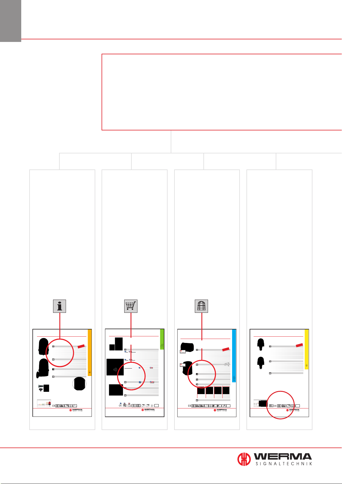
Where can I find ... ?
Customer satisfaction is our highest priority. Your wishes and requirements come
first at all times and with this in mind we are constantly improving our service and
product range.
To help find your way through our extensive catalogue we have compiled
a navi gation guide.
In this way you can find everything you need in no time at all !
Technical data Order
specifications
The product specific
technical data includes
dimensions, fixing options,
and connection possibilities.
This information can be
found on the relevant
product page in our catalogue under the heading
”Technical specifications”.
The order number of a
product is to be found
after the technical data
on the relevant page.
The order numbers for
specific colours and
voltages are listed here.
Accessories Weight, protection
rating, temperature,
sound output,
approvals
Our extensive range of
product accessories can
be found either immediately on the relevant
catalogue page or on the
following page.
Multi-Tone Sounder Combination
• Multi-Tone Sounder in combination
with LED Double Flash
• Sound output adjustable up to
114 dB (C)/110 db (A)
• 32 tones
TECHNICAL SPECIFICATIONS:
Dimensions (L x H x W): 109 mm x 112.5 mm x 152 mm
Housing: PC/ABS-Blend
Lens: PC, transparent
Base mounting
Connection: 24 V: Screw terminal with wire protection max. 1.5 mm
115/230 V: CAGE CLAMP
Cable entry: Membrane for cable diameter max. 13 mm
Fixing: Wall, base and ceiling mounting
Life duration: Up to 50,000 hrs (LED Double Flash)
Flash frequency: C. 1 Hz
ORDER SPECIFICATIONS:
Voltage 24 V AC/DC 115 V AC 230 V AC
Current consumption Optical 60 mA 30 mA 30 mA
Audible 200 mA 55 mA 30 mA
red 444 100 75 444 100 67 444 100 68
yellow 444 300 75 444 300 67 444 300 68
ACCESSORIES:
Cable gland M20 x 1.5 mm (for cable strain relief) 975 444 01
Wall mounting
Protection rating IP 65 is provided even without cable gland
TONE TYPES AND FREQUENCIES:
Selectable via DIP switch, see tone table on page 213.
QUICK AND SIMPLE MOUNTING
• 3 Tones can be triggered
externally
• Optical and audible signal can
be triggered separately
Life duration
up to 50,000 hrs
®
2
Important data relating to
our products can be found
on the relevant catalogue
page in form of pictograms.
The key to these icons is
to be found on page 346 of
this catalogue.
Optical-Audible
4
www.werma.com
Place the lower part of
the 444 Combination in
the desired position.
TECHNICAL DIAGRAMS: see page 305
See note
on page 347
Insert the connection
cable and screw into
terminal.
Secure the two parts
with the screws
supplied.
Secure the two
parts with the
screws supplied.
24 V
PLC
Page 6
Maß -
zeichnungen
271
IP65
+50°C
-20°C
97 g
103 g
Find everything
You are welcome to request the technical diagramsin digital form. The relevant 3D models, instruction leaflets
and connection diagrams can be obtained from us or downloaded from our homepage at any time.
ADDITIONAL INFORMATION:
www.werma.com
Technical
Diagrams
ORDER SPECIFICATIONS:
see page 270
ACCESSORIES:
TECHNICAL SPECIFICATIONS:
Optical Signal Devices
Free-standing Beacons • Permanent Beacons
Base mounting 220 Bracket mounting 223
Voltage 12-240 V 12-240 V
red 220 100 00 223 100 00
green 220 200 00 223 200 00
yellow 220 300 00 223 300 00
clear 220 400 00 223 400 00
blue 220 500 00 223 500 00
Further colours and voltages on request.
LED bulbBA15d
total length max. 42 mm
Voltage 24 V 115 V 230 V
Current consumption < 45 mA < 15 mA < 15 mA
red 956 100 75 956 100 67 956 100 68
green 956 200 75 956 200 67 956 200 68
yellow 956 300 75 956 300 67 956 300 68
white 956 400 75 956 400 67 956 400 68
blue 956 500 75 956 500 67 956 500 68
BulbBA15d, 7 W
total length max. 52 mm
Voltage 12 V 24 V 48 V 115 V 230 V
955 015 34 955 015 35 955 015 36 955 015 37 955 015 38
Housing: PA-GF, high impact
Lens: PC, transparent; Ring: PC/ABS-Blend
Connection: CAGE CLAMP
®
technology max. 2.5 mm
2
Contact protection according to VDE
Cable entry: Cable diameter max. 10 mm (220)
Cable diameter 3-6 mm (223)
PERMANENT BEACON 220 223
Fixing: Base mounting Bracket mounting
with flat seal cable gland
M 12 x 1.5 mm
Dimensions(Ø x Height): 75 mm x 79 mm 75 mm x 105 mm
Operating voltage: Max. 250 V Max. 250 V
Bulb socket: B15d, 10 Watt max. B15d,10 Watt max.
Bulb change: Via removal of lens Via removal of lens
Bulb not included in assembly.
Housing with
®
-Connection
• Available for base or bracket
mounting
• Connection without the need
to disassemble the product
220/223 Permanent Beacon
• Safe CAGE CLAMP
®
technology
•
B15d socket integrated
in the base
• Optimum illumination
Permanent Beacon 220
(Base mounting)
Permanent Beacon 223 with
integrated mounting bracket
Base
mounting
Bracket
mounting
you need
in no time
at all !
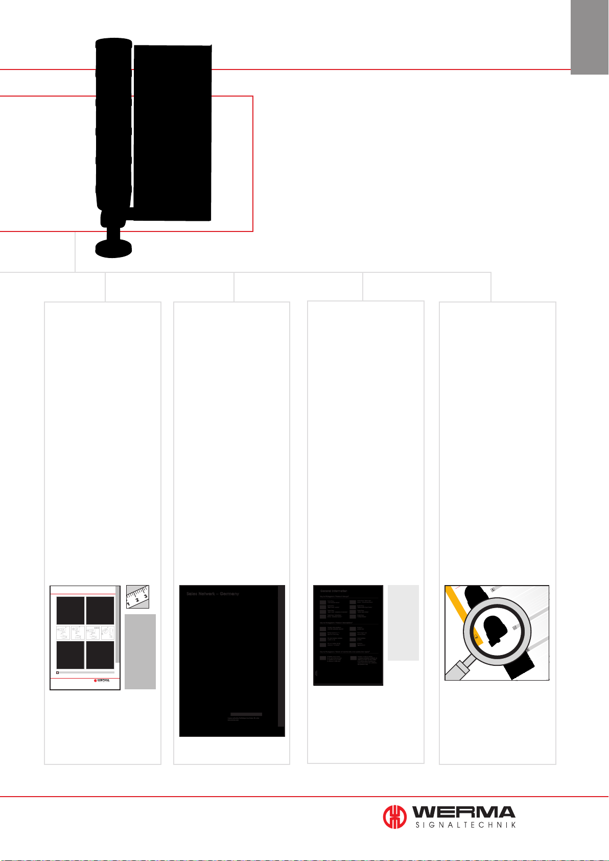
Contents
diagrams
A detailed drawing of
each product can be
found under the heading
”Technical Diagrams”
294
(from page
The exact page number
for the required drawing
is given on the product
page.
onwards).
Sales NetworkTechnical
In this section you can find
details of our subsidiary
companies and German
agencies (page 343).
Details of our international
sales network can be found
on www.werma.com.
General
information
Basic information and
explanations about our
products and services can
be found under the heading ”Technical Information”
(from page 346 onwards).
• Catalogue data
•
Norms and marks of
conformity
•
Meaning of optical and
audible signals
•
Sound output
•
Protection ratings
•
Many other interesting
pieces of information
Looking
for a specific
product?
If you are looking for
a specific product,
the quickest way to find
it is to look at our
”Article Number Index”
(page 364)
our ”Contents” (page 3).
or
www.werma.com
Diagrams
Technical
General
Information
5
Page 7
and Awards
New Products
New Products
Signal Towers · Modular
645/844 Vocal element for
KombiSIGN 70 and 71
• 102 dB high output vocal
element
• Sound output level can be
triggered externally
Page 41 + 56
640/840 Terminal element
M12 for KombiSIGN
70 and 71
• With practical M12 connector
• Quick and easy installation
Page 43 + 58
Signal Towers · Completely pre-assembled
698/699 LED Signal Tower
KOMPAKT 37
845 Terminal element with
CAGE CLAMP
for KombiSIGN 50
• Quick and easy wiring with
CAGE CLAMP
• Tube and single hole mounting
without the need for accessoires
Page 65
®
technology
®
technology
845 Terminal element
for KombiSIGN 50
• Tube and single hole mounting
without the need for accessoires
• Quick and easy wiring
Page 65
Optical Signal Devices · Installation Beacons
816 LED Permanent Beacon
Multicolour with clear and
opaque lens
239 LED permanent light
Multicolour with lens raised
• Pre-assembled signal tower with
max. 5 tiers
• With or without buzzer
Page 74 + 75
Optical Signal Devices · Free-standing Beacons
280 Low-intensity Obstacle
Light Type B
• with optional monitoring function
for the 230 V version
Page 145
281 Low-intensity Obstacle
Light Type B
• With robust glass/metal housing
• Salt water resistant
Page 146
• 7 colours in one beacon
• With clear or opaque lens
Page 111
• 5 colours in one beacon
• Multiple status warnings can
be signalled by one beacon
Page 102
6
www.werma.com
Page 8
Accessory
960 Corner Fixing Bracket 960 Foldaway base
NEW
and Awards
New Products
• For fixing on 90° corners
• Signal device is visible from
two sides
Page 68
• Signal tower can be folded
away
• Positioning in 0° and 90°
Page 69
Further information
The technical information, order specifications and
accessories for our new products can be found on the
relevant product page.
The technical diagrams of our new products are in the
”Technical diagrams“ section from page 294 onwards.
You are welcome to request the technical diagrams in
digital form. The relevant 3D models, instruction leaflets
and connection diagrams can be obtained from us or
downloaded from our homepage at any time.
The sounds of the audible and optical-audible
signal devices can be played from our website
www.werma.com.
www.werma.com
TIP
Configurator
The Signal Device Site on the internet: www.werma.com
You can select quickly and simply the required KombiSIGN signal tower,
Kompakt 37 or traffic light types 890/853/153 using this tool. The tool guides you
through the selection process with clear and concise images and questions and enables you to make your required selection in just a few mouse clicks.
7
Page 9
and Awards
New Products
Customised products
From your idea to the final product
Not without good reason do we claim to be European market and innovation leaders in signal technology. The customer is the focus of
all our activities.
Putting the customer first means that we have to be able to meet special requirements both in terms of design, manufacture, service and
availability. Our highly vertical manufacturing allows us to be very flexible and respond to your requests easily and quickly.
It goes without saying that we deliver quality and all of our products meet ISO 9001:2008.
Modular and pre-assembled signal towers
Signal
tower
element
Terminal
+ + +
element
Accessories
(example)
Cable and
Plug
Individual
Solution
WERMA is well known for its large range of modular signal towers.
We have an appropriate product/accessory for just about any application.
The modular system of signal towers allows you to customise the design
of the tower to your specific requirement. On request, products such as the
KombiSIGN towers can be supplied fully assembled or provided with a cable
or connector. This enables quick and simple installation on site.
Further features of our modular range of towers:
• Products for all common voltages
• Wide variety of optical and audible signal elements
• Mix and match according to your requirements
• Large selection of accessories
• Versatile and flexible solution possibilities
Customised design
Life in the modern industrial world is characterised by the fast pace of technological development. Guidelines for Corporate Identity and Corporate Design are being implemented
and experienced in all walks of business life, including also in the design of machinery
and equipment. The individual corporate design of a machine and its accessories conveys
the manufacturer‘s quality statement to the customer. Design, colour and aesthetics are
increasingly considered as important purchase criteria and the design of the product is
increasingly becoming a strategic competitive factor and is the key to strong innovation.
We are able to offer individual colours, designs and voltages for almost every signal
device. Uniform colour and design can enhance the overall appearance of the machine or
equipment upon which the signal device is fitted.
Design as a strategic competitive factor
The term design is of course fundamental to the development process of a piece of machinery and has mostly an effect on potential
purchasers when it is regarded as unique and special in some way. It is very important that all components fit and work together perfectly, since signal devices are visible and form part of the design of the machine.
Simply specify us the design you want and we will do the rest. Experts will advise you on design options in order to get the best
possible result: aesthetics and signal technology merged into your customised signal device.
8
www.werma.com
Page 10
Award-winning design
Design and function must be right - from the very start
From the outset, we ensure that only select and high-quality materials are employed to guarantee that our products operate safely and reliably. WERMA signal devices need tostand out. At the same time, they must blend into the background when non-operational. We therefore
carefully create optimum light and perfect sound in all WERMA products - and dedicate considerable effort to making them look good.
Christian Höhler, WERMA R + D Director explains: „Aesthetics and quality are important. Both must
enhance the products‘ signalling function in the best way possible! To this end, we frequently work
with external designers. These designers ensure that WERMA products look attractive. Our engineers
are then responsible for creating the highest level of
functionality.
In this way we create an attractive form for the best possible signalling performance.
We want our customers to benefi t from their WERMA signal devices for a long time to come!“
WERMA designer products provide many benefits
WERMA signal devices are attractive in design. In our opinion, good
design means that:
• WERMA products are aesthetically pleasingand innovative
• Designs for all tastes are available to ensure our customers are
in line with current trends
• WERMA signal devices are ergonomic and function reliably
Customers benefi t from a product that:
• is perfectly suited to their application
• either blends into the background or purposely stands out
• worksperfectly and looks fantastic
The end result is a high-quality housing combined with the best of
signalling functions for your machine - all designed to increase the
quality and reliability of your application.
and Awards
New Products
Award-winning design by WERMA
Experts regularly assess the design quality of WERMA products. Products that meet the strict requirements are awarded the most highlyregarded design prizes from all over the world:
LED Signal Tower
deSIGN 42
LED Traffic Light
894
Beacon 885
LED Signal Tower
VarioSIGN 690
424/425 Combination Rotating Mirror
434/435
Combination
444 Combination
TOP 100
www.werma.com
9
Page 11

Systems
Page 12
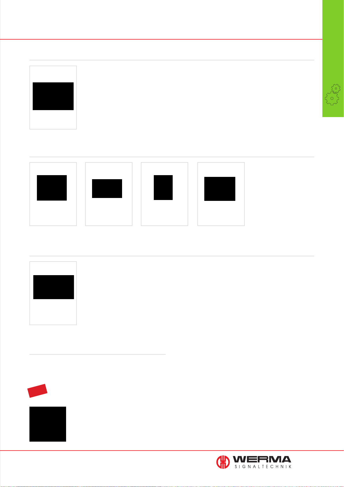
Overview Systems for Process Optimisation
in Production, Assembly and Logistics areas
Machine Data Collection Systems (MDC Systems)
WIN - Wireless
Information Network
For KombiSIGN
70 and 71
Page 12
Manual Call Systems
AndonCONTROL Connection Set
For KombiSIGN
70 and 71
Page 22
AndonSWITCH AndonBOX
For signal towers
Page 23
For signal towers
Page 24
For KombiSIGN
70 and 71
Page 25
Systems
Wireless Call Systems
KombiSIGN
reflect
For KombiSIGN
70 and 71
Page 27
Further Information
Further Information about „KombiSIGN signal towers“ can be found in
the chapter „Signal Towers“ beginning on page 29.
TIP
You can find more information on these products at www.werma.com.
www.werma.com
11
Page 13
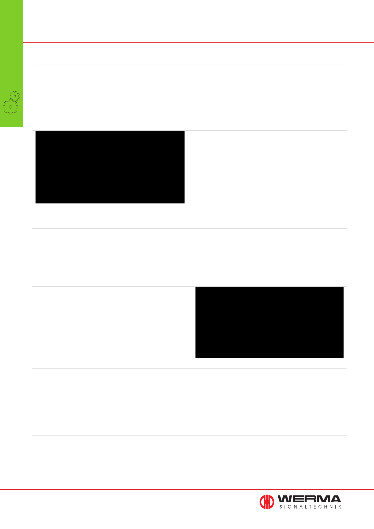
MDC Systems
MDC Systems
•
Recognise the potential with WIN
Systems
Delivery performance, smaller batch sizes, increasing competition
and pressure on costs are all common issues for companies nowadays. In order to deal with all of these issues greater attention
has to be paid to flexibility, transparency and efficiency.
Without technical support it is virtually impossible to reduce
downtime, shorten production times and at the same time install a
comprehensive works monitoring system in order to make the best
use of the capacity available.
Machine Shop Monitoring quickly and simply with WIN
WERMA offers an easy to install simple low cost wireless monitoring system called WIN (Wireless Information Network) which can
be fitted to virtually any piece of equipment or machinery, irrespective of age and specification. WIN combines signal tower technology with wireless technology and an ingenious software package.
The common interface point on machines is a WERMA signal tower
to which the WIN (MDC - Machine Data Collection) system can be
easily fitted and commissioned.
Analyse Productivity at the touch of a button with WIN
An additional element called the “WIN slave/transmitter” is fitted
to the KombiSIGN signal tower. This transmitter transfers machine
status information wirelessly to the “WIN master/receiver”.
The “WIN master/receiver” is connected by USB to a PC and can
receive data from up to 50 “WIN slaves/transmitter” each reporting
a maximum of 8 different status conditions.
Counter module with WIN slave performance/WIN transmitter performance
The second piece of hardware called “WIN slave performance/
transmitter performance” offers a counting module alongside the
traditional monitoring functions. This module monitors up to six
different status conditions and counts the piece part output signal
from a machine.
Excellent transmission range with Wireless Technology
The WIN system has a transmission range (unobstructed line of
sight) of 300 m although this will vary according to the construction of the building. In addition, as each “WIN slave/transmitter”
acts as a repeater, effective transmission distances in a network of
“WIN slaves/transmitter” can be extended to a maximum of
900 m distance between “WIN slave/transmitter” and “WIN master/
receiver”. The low frequency (EU: 868 MHz/USA: 915 MHz) the
system uses provides better transmission characteristics than other
systems such as WLAN and Bluetooth.
The intuitive WIN software
The software supplied with the system is licence-free and easy
to install. There is no restriction on the number of users who may
wish to install and run the program.
The software displays the status condition of signal lights installed
in the system and the user can select from three languages, German, English or French. The software enables the user to analyse
runtimes, identify causes of disruption in operations and therefore
improve efficiency.
12
www.werma.com
Page 14
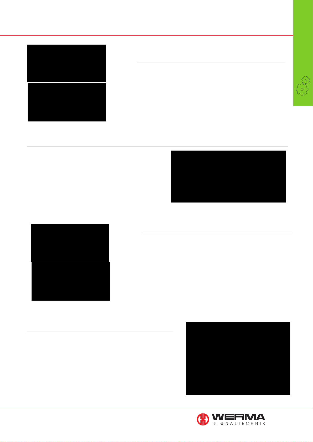
WIN - Software information and functions at a glance
React quickly
with the Control Station
You can quickly see if a machine is in an error condition or running normally. This module helps you to quickly take action to reduce downtime.
The messaging function keeps you in touch all the time
It is no problem for WIN to keep you informed anytime anywhere
about condition changes. For example a condition change can
trigger an email to be sent automatically to a PC or smart phone.
You can select for which machines and which condition changes
an email is generated and also set a time delay before the email is
sent.
MDC Systems
•
Systems
Increase efficiency
with the Productivity Module
Using the Productivity Module you can check the productivity of your machines and workstations over any time period. You can look for example at
the last working day, or define specific time periods such as shift patterns.
Using this module it is possible to retrospectively analyse downtime and fault
conditions and thus help improve efficiency in the future.
Production transparency
in the Runtime module
The Runtime Module allows you to check the operation and downtimes of
your machines or workstations. Using this module you will quickly establish
if there are patterns of downtime or fault conditions thus giving you a better
transparency of production. This will then form the basis for improving the
efficiency of your production processes.
www.werma.com
13
Page 15
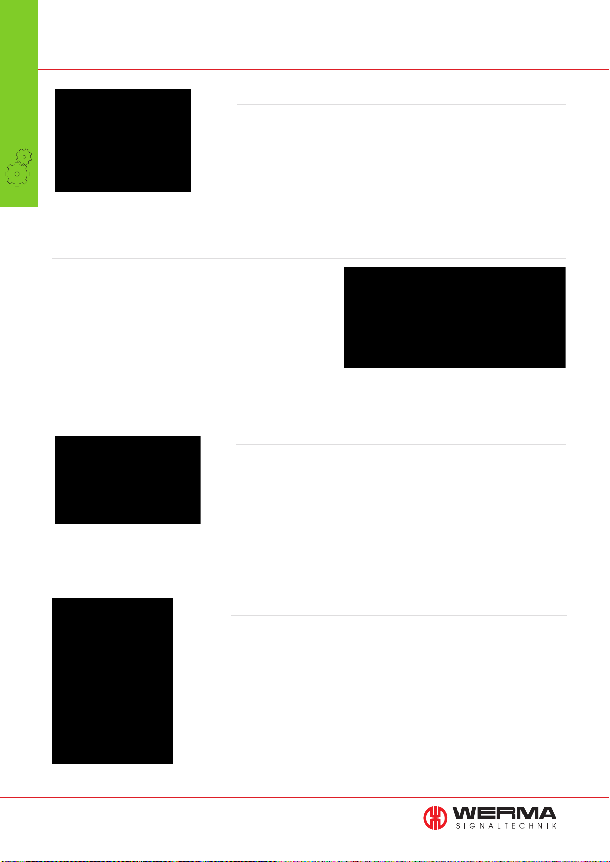
WIN - Software information and functions at a glance
MDC Systems
•
Document problems with the error analysis
Systems
Identify, comment and analyse the fault conditions. First of all define the most common
reasons for fault status occurring, for example material shortage. Should this condition,
or any other defined condition arise, once you have identified the reason for the fault
condition this can be entered as a “note” in the Runtime Module.
The number of fault conditions will also be shown and thus will assist in resolving the
reasons for the frequency of particular fault conditions.
Include a range of users with the Multiple Operator Access
The software uses a structure based on a database and can be used
by any number of users. The database needs to be copied over to a
shared drive on your network to allow multiple users access to the
system. There is no restriction on the number of users who can install
the licence-free software and work with it. All users who have the
software installed on their PC and have access to the shared drive
database can see the performance of machines or workstations in
real time and edit the views to their personal requirements.
Overview of jobs being run
The module gives you a comprehensive overview of which job is running on which
machine and how the job is progressing. Future planned jobs are shown as “waiting”
and can be initiated as soon as the machine required is available.
Stability of the Network with the Routing Module
The Routing Module assists in setting up or adjusting the best network for WIN.
The route network graphic shows the current set up of the WIN network and the
signal strength of each “WIN slave/transmitter” or WIN slave performance/transmitter
performance“. Each “WIN slave/transmitter” will automatically select
the best route back to the “WIN master/receiver” either directly, or indirectly.
14
www.werma.com
Page 16
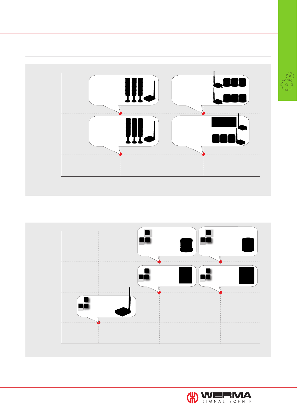
Quick Finder - MDC Systems
Starter Kits
FUNCTION
WIN complete
performance
KombiSIGN 71
Page 17
Machine status
and part count
monitoring
WIN complete
KombiSIGN 71
Page 17
Machine status
monitoring
WIN system performance
KombiSIGN 71 Page 17
WIN system performance
KombiSIGN 70 Page 19
WIN system
KombiSIGN 71 Page 17
WIN system
KombiSIGN 70 Page 19
MDC Systems
•
Systems
Additional Items
FUNCTION
Machine status
and part count
monitoring
Machine status
monitoring
Receiver
KombiSIGN 70/71
WIN master
WIN receiver
Page 17 + 19
without
WIN slave performance
WIN transmitter
performance
Page 17
WIN slave
WIN transmitter
Page 17
KombiSIGN 70/71
available
WIN slave performance
WIN transmitter
performance
Page 19
WIN slave
WIN transmitter
Page 19
SIGNAL
TOWER
PC KombiSIGN 71 KombiSIGN 70
SIGNAL
TOWER
Please check the wireless frequency. In Europe the version with 868 MHz is used. In North America the version with 915 MHz is used.
Please enquire about use in other countries.
www.werma.com
15
Page 17
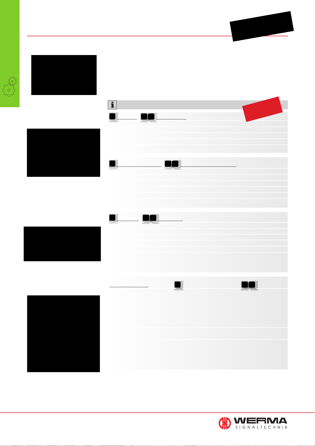
860 WIN for KombiSIGN 71
MDC Systems
•
Systems
• Economical wireless-based
Machine Data Collection system
(MDC system)
• Analyse and improve production
processes
• Monitor the status of machines
• Easy to install, intuitive software
WIN slave/transmitter and
WIN slave performance/
transmitter performance
The software package allows you to
monitor a production area or
individual workstations from
the comfort of the PC
The counter impulse of the WIN slave/
transmitter performance is max. 10 Hz
TECHNICAL SPECIFICATIONS:
WIN slave / WIN transmitter
Dimensions (Ø x Height): 70 mm x 65.5 mm
Housing: PC, black
Connection: Bayonet
Operating voltage: 24 V AC/DC
Current consumption: 40 mA, max. 430 mA
WIN slave performance / WIN transmitter performance
Dimensions (Ø x Height): 70 mm x 65.5 mm
Housing: PC, black
Connection: Bayonet
Operating voltage: 24 V AC/DC
Current consumption: 40 mA, max. 430 mA
Counter input: Max. 10 Hz
WIN master / WIN receiver
Dimensions (L x H x W): 76 mm x 30 mm x 80 mm (without antenna)
Housing: ABS, black
Connection: Via USB
Operating voltage: Via USB (5 V DC)
Current consumption: < 100 mA
Counter input:
Windows 8, Windows Server 2003 SP 2,
Windows Server 2008
Windows XP SP 3, Windows Vista SP 2, Windows 7,
approved
Patent
Expandable at any time: With
additional “WIN slaves/transmitter”
up to 50 machines can be
integrated into the network
16
www.werma.com
Wireless connection
ISM frequency: 868 MHz 915 MHz
(WIN conforms to the EU’s (only for use in
EN 300220 harmonised North America)
standard and can thus be
used in all EU member
countries.)
Further countries upon request
Transmission range: Up to 300 m (unobstructed line of sight)
Every WIN slave (performance) / WIN transmitter
(performance) simultaneously functions as a “repeater”,
enabling the transmission range to be signifi cantly increased.
Page 18
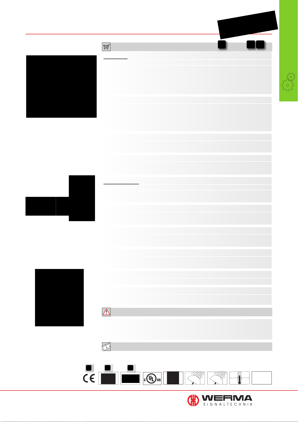
ORDER SPECIFICATIONS:
MDC Systems
•
“WIN complete” is immediately
ready for use and consists of three
signal towers, three WIN slaves/
transmitters (performance) and
the WIN master/receiver
STARTER KITS
WIN complete for KombiSIGN 71 860 640 03 860 640 06
Assembly: WIN master/receiver, 3 WIN slaves/transmitters
)
KombiSIGN 71 (pre-confi gured
, 3 signal towers
KombiSIGN 71 (LED permanent light elements in red, yellow
and green, terminal element, base with integrated tube),
software, USB cable
WIN complete performance KombiSIGN 71 860 640 13 860 640 16
Assembly: WIN master/receiver,
performance KombiSIGN 71 (
3 signal towers KombiSIGN 71
3 WIN slaves/transmitters
pre-confi gured)
,
(LED permanent light elements
in red, yellow and green, terminal element, base with
integrated tube),
software,
USB cable
WIN system for KombiSIGN 71 860 640 01 860 640 04
Assembly: WIN master/receiver, 3 WIN slaves/transmitters
KombiSIGN 71 (pre-confi gured), software, USB cable
WIN system performance for KombiSIGN 71 860 640 11 860 640 14
Assembly:
performance KombiSIGN 71 (
WIN master/receiver 3 WIN slaves/transmitters
pre-confi gured
), software,
USB cable
ADDITIONAL ITEMS
WIN slave for KombiSIGN 71 860 640 02 -
Assembly: WIN slave (not pre-confi gured)
Both networks can be fi tted with up to 50 WIN slaves.
Systems
Fit WIN slaves/transmitters to an
existing WERMA signal tower
and connect the
WIN master/receiver to the PC
Machine status and part count
monitoring in one element:
WIN slave performance/
WIN transmitter performance
WIN transmitter for KombiSIGN 71 - 860 640 05
Assembly: WIN transmitter (not pre-confi gured)
Both networks can be fi tted with up to 50 WIN transmitters.
WIN slave performance for KombiSIGN 71 860 640 12 -
Assembly: WIN slave performance (not pre-confi gured)
The network can be expanded to up to 50 WIN slaves performance per network as required.
WIN transmitter performance for KombiSIGN 71 - 860 640 15
Assembly: WIN transmitter performance (not pre-confi gured)
The network can be expanded to up to 50 WIN transmitter performance per network as required.
WIN master 860 000 00 -
Assembly: WIN master with USB cable, software
WIN receiver - 860 000 01
Assembly: WIN receiver with USB cable, software
ADDITIONAL INFORMATION:
Please check the wireless frequency. In Europe the version with 868 MHz is used.
In North America the version with 915 MHz is used. Please enquire about use in other
countries.
TECHNICAL DIAGRAMS:
see page 322
www.werma.com
860 640 05
860 640 15
See note
on page 347
860 640 X2
860 640 X5
IP 65
860 000 0X
IP 20
+50°C
PLC
-20°C
17
Page 19
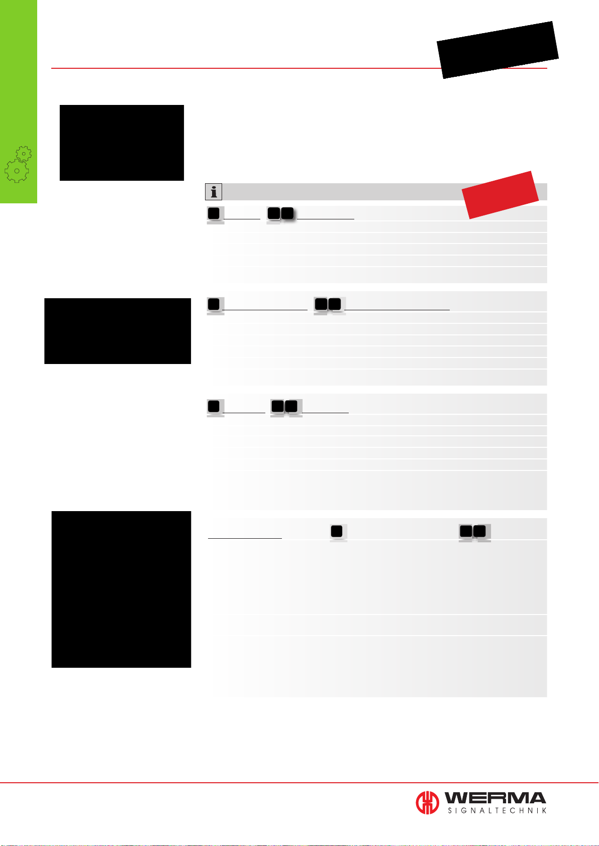
860 WIN for KombiSIGN 70
MDC Systems
•
Systems
• Economical wireless-based
Machine Data Collection system
(MDC system)
• Analyse and improve production
processes
• Monitor the status of machines
• Easy to install, intuitive software
WIN slave/transmitter and
WIN slave performance/
transmitter performance
The counter impulse of the WIN slave/
transmitter performance is max. 10Hz
TECHNICAL SPECIFICATIONS:
WIN slave / WIN transmitter
Dimensions (Ø x Height): 70 mm x 65.5 mm
Housing: PC, black
Connection: Bayonet
Operating voltage: 24 V AC/DC
Current consumption: 40 mA, max. 430 mA
WIN slave performance / WIN transmitter performance
Dimensions (Ø x Height): 70 mm x 65.5 mm
Housing: PC, black
Connection: Bayonet
Operating voltage: 24 V AC/DC
Current consumption: 40 mA, max. 430 mA
Counter input: Max. 10 Hz
WIN master / WIN receiver
Dimensions (L x H x W): 76 mm x 30 mm x 80 mm (without antenna)
Housing: ABS, black
Connection: Via USB
Operating voltage: Via USB (5 V DC)
Current consumption: < 100 mA
Counter input:
Windows 8, Windows Server 2003 SP 2,
Windows Server 2008
Windows XP SP 3, Windows Vista SP 2, Windows 7,
approved
Patent
The WIN system has a transmission
range (unobstructed line of sight)
of 300 m
18
www.werma.com
Wireless connection
ISM frequency: 868 MHz 915 MHz
(WIN conforms to the EU’s (only for use in
EN 300220 harmonised North America)
standard and can thus be
used in all EU member
countries.)
Further countries upon request
Transmission range: Up to 300 m (unobstructed line of sight)
Every WIN slave (performance) / WIN transmitter
(performance) simultaneously functions as a “repeater”,
enabling the transmission range to be signifi cantly increased.
Page 20
ORDER SPECIFICATIONS:
MDC Systems
•
Plug and play with WIN system:
Fit WIN slaves to an existing WERMA
signal tower and connect the WIN
master/receiver to the PC
STARTER KITS
WIN system for KombiSIGN 70 860 840 01 860 840 04
Assembly: WIN master/receiver, 3 WIN slaves/transmitters
KombiSIGN 70 (pre-confi gured), software, USB cable
WIN system performance for KombiSIGN 70 860 840 11 860 840 14
Assembly:
performance KombiSIGN 70 (
WIN master/receiver 3 WIN slaves/transmitters
pre-confi gured
), software,
USB cable
ADDITIONAL ITEMS
WIN slave for KombiSIGN 70 860 840 02 -
Assembly: WIN slave (not pre-confi gured)
Both networks can be fi tted with up to 50 WIN slaves.
WIN transmitter for KombiSIGN 70 - 860 840 05
Assembly: WIN transmitter (not pre-confi gured)
Both networks can be fi tted with up to 50 WIN transmitters.
WIN slave performance for KombiSIGN 70 860 840 12 -
Assembly: WIN slave performance (not pre-confi gured)
The network can be expanded to up to 50 WIN slaves performance per network as required.
WIN transmitter performance for KombiSIGN 70 - 860 840 15
Assembly: WIN transmitter performance (not pre-confi gured)
The network can be expanded to up to 50 WIN transmitter performance per network as required.
Systems
The software shows the status
of signal towers connected
to the system
Expand the network at any time.
You can monitor up to 50 machines
within the WIN system
WIN master 860 000 00 -
Assembly: WIN master with USB cable, software
WIN receiver - 860 000 01
Assembly: WIN receiver with USB cable, software
ADDITIONAL INFORMATION:
Please check the wireless frequency. In Europe the version with 868 MHz is used.
In North America the version with 915 MHz is used. Please enquire about use in other
countries.
TECHNICAL DIAGRAMS:
see page 323
www.werma.com
860 840 05
860 840 15
See note
on page 347
860 840 X2
860 840 X5
IP 54
860 000 0X
IP 20
+50°C
PLC
-20°C
19
Page 21
Manual
•
Call Systems
Systems
Manual Call Systems
Andon products for process optimisation
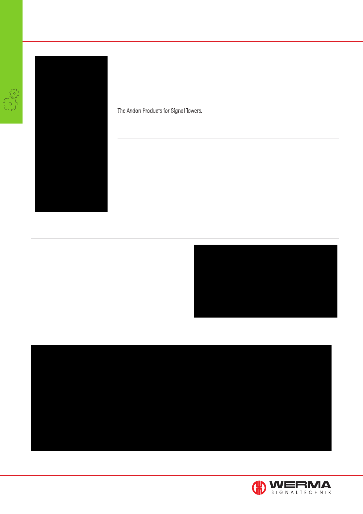
Production and logistics experts are increasingly focussing on the implementation of lean management methods. The aim of a holistic approach to lean management is to optimally coordinate every
activity within the value creation chain and thus eliminate all types of waste.
WERMA now offers an optimal solution for lean production implementation:
The Andon Products for Signal Towers.
What does “Andon” stand for?
The term
“Andon” originates from Japan. A signal tower or beacon mounted in a prominent positi-
on signals that a problem has arisen and requests an immediate response.
WERMA‘S manual call systems function according to the same principle: when an optical or
audible signal is activated the supervisor or logistics employee is made aware of the fact that an
immediate response is required. Each workstation that is equipped with these products enables the
employee to precisely and instantaneously signal which type of issue has occurred at the touch of
a button. With the aid of optical and/or audible signals the system then displays the corresponding
information.
Flexible call system
The use of call systems not only improves the efficiency of production processes but decisively contributes to the effective use of
resources, creates cost savings and increases the ability to flexibly
respond to market changes.
WERMA‘S manual call systems can be used in a wide range of
applications: from optimising kanban processes to production
workstations or packaging areas in shipping departments.
Occurrence Signalisation Response
Stop
Material
Support
AndonCONTROL streamlines the delivery of material to manual workstations
If an employee at a manual
workstation sees that a specific
material is no longer available,
then she presses the corresponding AndonCONTROL button.
20
As soon as the button is pressed
an optical signal immediately
displays that material is needed.
The logistics employee receives
the optical signal and can respond
at once. He collects the requested
material from the storage area.
Without delay, the required
material is delivered directly to
the workstation.
Page 22
Quick Finder - Manual Call Systems
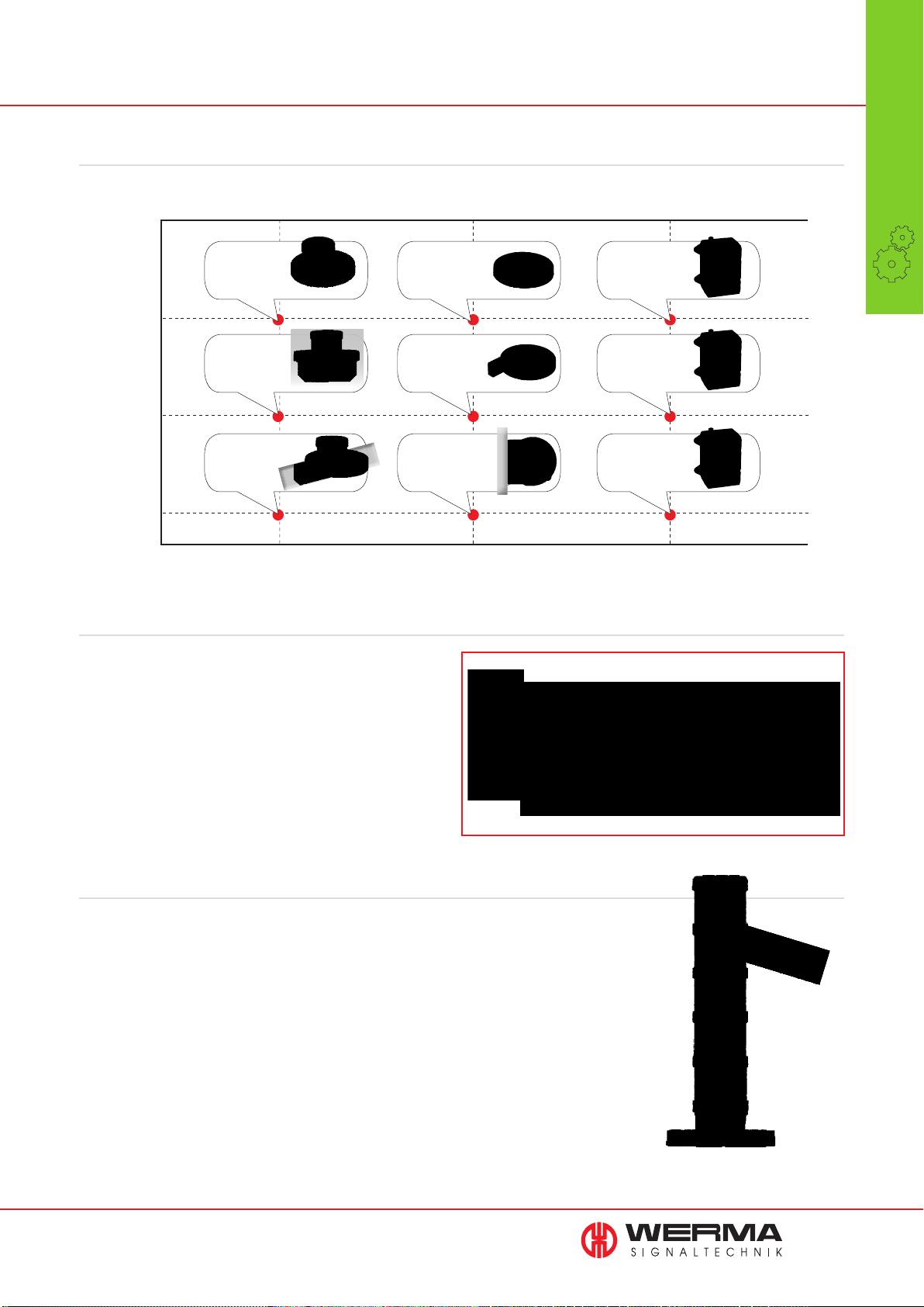
Quick Finder: Installation type, position of signal tower and number of status conditions that can be activated
TYPE OF
INSTALLATION
Base
mounting
Wall
mounting
Signal tower mounted
directly on Andon product
AndonCONTROL
Page 22
AndonCONTROL
+ Bracket 975 883 01
Page 22
Signal tower mounted
separately from Andon product
AndonSWITCH
Page 23
AndonSWITCH
+ Bracket 975 883 01
Page 23
Signal tower mounted
separately from Andon product
AndonBOX
Page 24
AndonBOX
Page 24
POSITION OF THE
SIGNAL TOWER
Manual
•
Call Systems
Systems
Mounting
on aluminium
profile
AndonCONTROL
+ Bracket 975 883 01
Page 22
8 States 8 States 4 States
AndonSWITCH
+ Bracket 975 883 01
Page 23
Wireless technology provides a complete overview
In larger production areas several workstations are often
outside of the supervisor‘s line of sight. For situations such
as these WERMA offers an optimal solution: a combination
of manual call systems and MDC systems creates a central
overview of the current status of up to 50 workstations at the
same time.
Simple integration of the
“WIN slave/transmitter” into the signal
tower enables this supplementary function to be used. The WIN
slave/transmitter transmits data via wireless technology to the
WIN master/receiver, which is connected to a central PC.
Process optimisation and greater efficiency
AndonBOX
Page 24
NUMBER OF
STATUS
CONDITIONS
With the help of the user-friendly WIN software, various productivity analysis tools can also be
implemented. The concise software display interface enables intuitive operation and helps to gain
a good overview of the integrated workstations.
The WIN system is also equipped with a messaging functionality. WIN sends occurrence-specifi c
e-mails so that information is reliably and punctually transmitted to the correct person, independent of their location. The main aim is to achieve shortened response times and greater effi ciency
for specifi cally defi ned processes whilst ensuring clearly defi ned areas of responsibility amongst
production staff. In large production departments, the reduction in workload and inestimable time
and cost benefi ts are particularly valuable.
21
Page 23
860 AndonCONTROL for
Manual
•
Call Systems
Systems
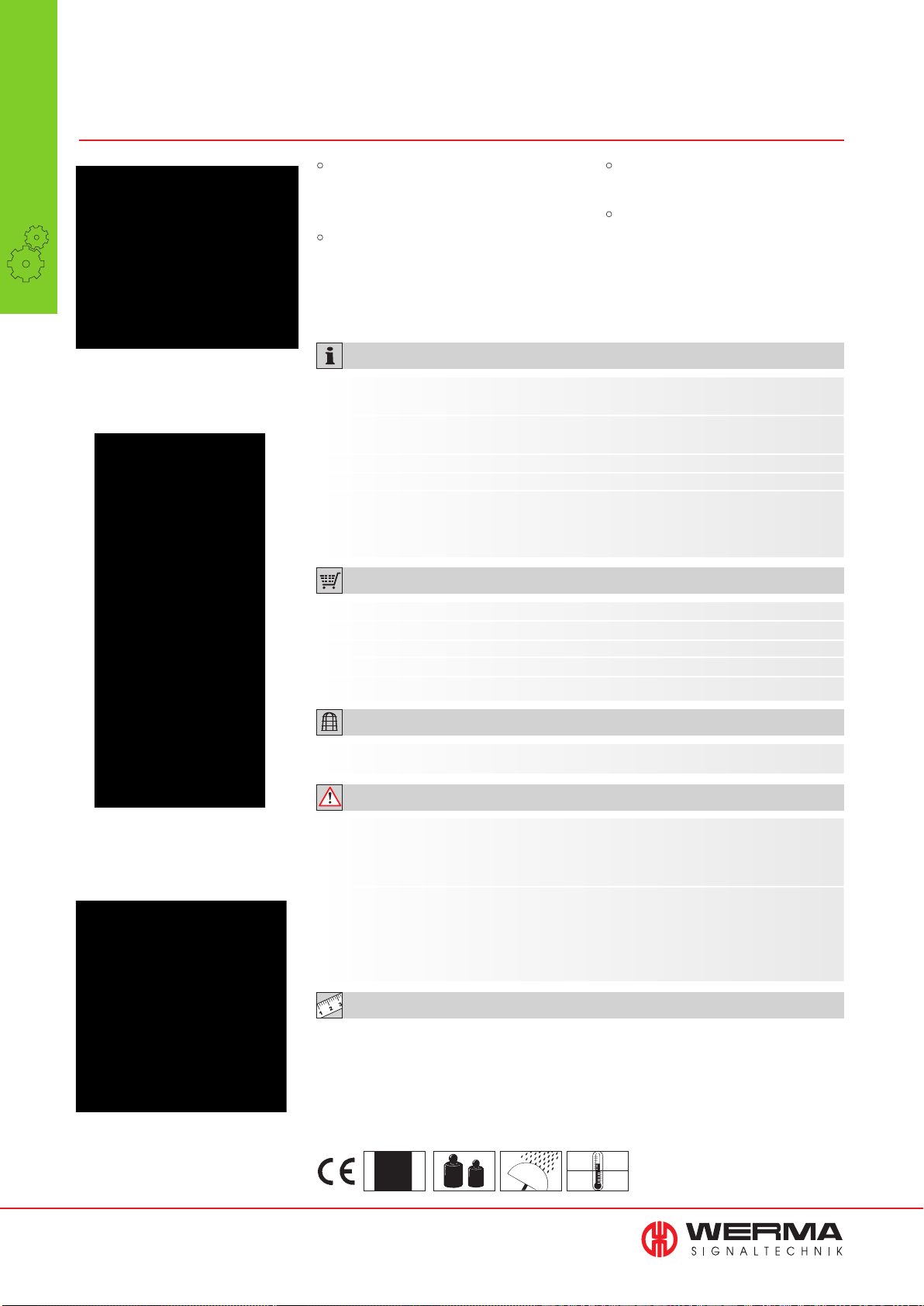
AndonCONTROL is a simple
call system for a wide variety
of applications
KombiSIGN 70 and 71
• Instant status display at the touch
of a button to aid process
optimisation
• Smart electronics enable the
activation of up to eight
different states
TECHNICAL SPECIFICATIONS:
Dimensions (Ø x Height):
Housing:
Fixing:
Number of signal elements:
Assembly:
KombiSIGN 70: 136 mm x 49.5 mm
KombiSIGN 71: 136 mm x 45.5 mm
Base: PC/ABS
Terminal element: PA-GF, shock resistant
Base mounting, Bracket mounting (accessory)
Max. 4 additional signal elements possible
AndonCONTROL, power supply unit with connection
cable (length 1.8 m), interchangeable adoptors for EU,
UK, North America, rubber feet, cable connection
• For use with an integral
signal tower
• Universal power supply and
interchangeable adaptors
enable worldwide use
Instant status activated
by push button
Operation
Material
ORDER SPECIFICATIONS:
Voltage power supply unit
Voltage signal elements
Current consumption
AndonCONTROL for KombiSIGN 70
AndonCONTROL for KombiSIGN 71
100-240 V AC
24 V DC
Max. 1 A
860 840 07
860 640 07
ACCESSORIES:
Mounting bracket, metal 975 883 01
ADDITIONAL INFORMATION:
The smart electronics in AndonCONTROL can activate up to eight different status conditions
(permanent or blinking light). A signal tower mounted directly on the AndonCONTROL
product can signal the different states.
Suitable for all KombiSIGN 70 and 71 signal towers.
Further information and order details for KombiSIGN 70 and 71 can be found in the chapter
“modular signal towers” on page 29.
TECHNICAL DIAGRAMS:
see page 324
Warning
The four push buttons can
be individually labelled
22
Error
See note
on page 347
375 g
IP 20
+40°C
0°C
Page 24
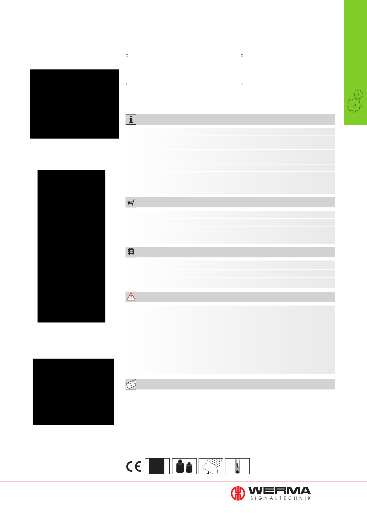
860 AndonSWITCH for signal towers
• A simple call system for various
applications such as manual
workstations
• Smart electronics with illuminated
switches enable the activation of up
to eight different states
TECHNICAL SPECIFICATIONS:
• For use with a signal tower
installed away from the Andon
product
• Universal power supply and
interchangeable adaptors
enable worldwide use
Manual
•
Call Systems
Systems
AndonSWITCH helps visualise the
active state via illuminated switches
Dimensions (Ø x Height):
Housing:
Fixing:
Connection:
Number of signal elements:
Assembly:
136 mm x 19 mm
Base: PC/ABS
Terminal element: PA-GF, shock resistant
Base mounting, Bracket mounting (accessory)
Via M12 plug (8 pole)
Max. 4 additional signal elements possible
AndonSWITCH, power supply unit with connection
cable (length 1.8 m), interchangeable adoptors for EU,
UK, North America, rubber feet, cable connection
ORDER SPECIFICATIONS:
Voltage power supply unit
Voltage signal elements
Current consumption
AndonSWITCH
100-240 V AC
24 V DC
Max. 1 A
860 000 04
ACCESSORIES:
Mounting bracket, metal
Cable 5 m with M12 plug (8 pole)
Cable 5 m with M12 connector and plug (8 pole) 960 000 46
975 883 01
960 860 01
ADDITIONAL INFORMATION:
The mounting bracket can be used
to fix AndonSWITCH to an aluminium
profile and activate a remote signal
tower
Interchangeable adaptors (included
in assembly) and wide input voltage
range make the Connection Set
suitable for worldwide use
The smart electronics and illuminated switches of AndonSWITCH can activate up to eight
different status conditions (permanent or blinking light). A signal tower installed away from
the Andon product using a connection cable can signal the different states.
Suitable for all KombiSIGN signal towers.
Further information and order details for the modular KombiSIGN 70 and 71 can be found
in the chapter “modular signal towers” on page 29 and for the “pre-assembles” signal
towers on page 71.
TECHNICAL DIAGRAMS:
see page 321
See note
on page 347
350 g
IP 20
+40°C
0°C
23
Page 25
Manual
•
Call Systems
Systems
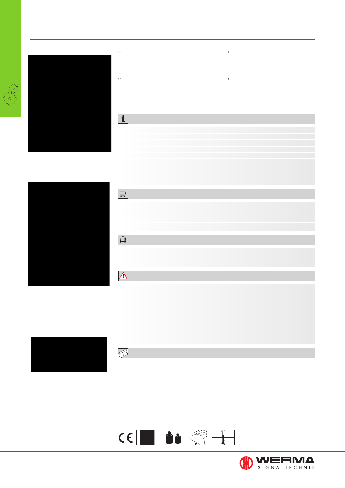
860 AndonBOX for Signal Towers
AndonBOX for use in
industrial applications
• Instant status display at the touch
of a button to aid process optimisation
• The robust AndonBOX is ideally
suited to meet the demands of
industrial applications
TECHNICAL SPECIFICATIONS:
Dimensions (B x H x T): 161 mm x 79 x 138 mm
Housing: PA
Fixing: Base mounting, Wall mounting
Connection: Via M12 plug (8 pole)
Number of signal elements: Max. 4 additional signal elements possible
Assembly: AndonBOX, power supply unit with connection cable
(length 1.8 m), interchangeable adoptors for EU, UK,
North America, coloured switch caps (red, yellow, green,
white, blue)
ORDER SPECIFICATIONS:
• For use with a signal tower
installed away from the Andon
product
• Universal power supply and in-
terchangeable adaptors enable
worldwide use
The switch caps can be easily
clicked into place; space is also
available for additional labelling
Voltage: power supply unit
Voltage: signal elements
Current consumption
AndonBOX
100-240 V AC
24 V DC
Max. 1 A
860 000 03
ACCESSORIES:
Cable 5 m with M12 plug (8 pole)
Cable 5 m with M12 connector and plug (8 pole) 960 000 46
960 860 01
ADDITIONAL INFORMATION:
Up to four different status changes can be activated using the four push button switches on
the robust AndonBOX. A signal tower installed away from the box using a connection cable
can signal the different states.
Suitable for all KombiSIGN signal towers.
Further information and order details for the modular KombiSIGN 70 and 71 can be found
in the chapter “modular signal towers” on page 29 and for the “pre-assembles” signal
towers on page 71.
TECHNICAL DIAGRAMS:
see page 321
Coloured coded switch caps
in five different colours:
yellow, red, green, blue, white
24
See note
on page 347
590 g
IP 20
+40°C
0°C
Page 26
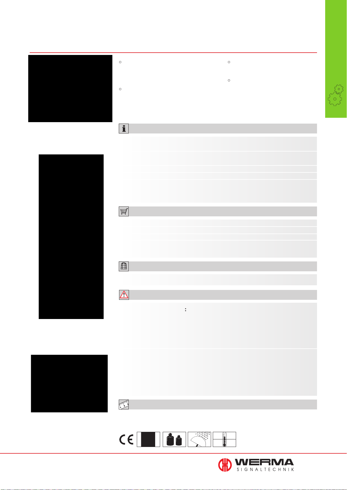
860 Connection Set for
The Connection Set is
available for KombiSIGN 70
and 71 signal towers
KombiSIGN 70 and 71
• Ideal supplement to “WIN”
(Wireless Information Network) to
expand the transmission range
• Signal Tower “reflection” to any
location with the aid of
KombiSIGN reflect
TECHNICAL SPECIFICATIONS:
Dimensions (Ø x Height): KombiSIGN 70: 136 mm x 49.5 mm
KombiSIGN 71: 136 mm x 45.5 mm
Housing: Base: PC/ABS
Terminal element: PA-GF, shock resistant
Fixing: Base mounting, Bracket mounting (accessory)
Number of signal elements: Max. 4 additional signal elements possible
Assembly: Connection Set, power supply unit with connection
cable (length 1.8 m), interchangeable adoptors for EU,
UK, North America, rubber feet, cable connection
ORDER SPECIFICATIONS:
• Simple installation as no
additional cable is required
• Universal power supply and
interchangeable adaptors
enable worldwide use
Manual
•
Call Systems
Systems
With the aid of the connection set,
the master/receiver from
KombiSIGN reflect can be used
wherever an electrical
socket is available
Voltage power supply unit
Voltage signal elements
Current consumption
Connection Set for KombiSIGN 70
Connection Set for KombiSIGN 71
100-240 V AC
24 V DC
Max. 1 A
860 840 08
860 640 08
ACCESSORIES:
Mounting bracket, metal 960 860 01
ADDITIONAL INFORMATION:
• Use with KombiSIGN reflect: The KombiSIGN reflect master/receiver in conjunction with
the Connection Set can be used anywhere an electrical socket is available. In this way, the
status warning displayed by a remote signal tower can be “reflected” for example to an
office location.
Information and order details for KombiSIGN reflect can be found on pages 26 and 27.
• Use with WIN: Together with the Connection Set each WIN slave/transmitter can be
installed as a “repeater” anywhere an electrical socket is available, thus expanding the
transmission range.
Further information on WIN can be found on page 12.
Interchangeable adaptors
(included in assembly) and wide
input voltage range make the
Connection Set suitable for
worldwide use
TECHNICAL DIAGRAMS:
see page 323
See note
on page 347
335 g
IP 20
+40°C
0°C
25
Page 27
Wireless
•
Call Systems
Systems
Wireless Call Systems
Get your machines in view with KombiSIGN reflect
Do you want
• to monitor machines that are out of view?
• to improve the productivity and effi ciency of your
machines?
• to react quickly and safely in the event of malfunctions?
• to save costs?
Then WERMA has the solution for you!
Signal tower „reflection“
WERMA Signaltechnik provides a simple solution for the remote wireless
monitoring of machinery.
KombiSIGN refl ect “refl ects” the status of the machine to a signal tower
within your line of sight. This enables you to wirelessly monitor machines
situated at a greater distance and respond quickly to malfunctions.
With KombiSIGN refl ect, even machines which were not previously
network-capable can now be remotely monitored.
KombiSIGN refl ect is available for the WERMA KombiSIGN 70 and 71
signal tower ranges. The kit consists of two elements that transmit and
receive the data via wireless signal (slave/transmitter and master/receiver).
* slave and master transmitter and receiver
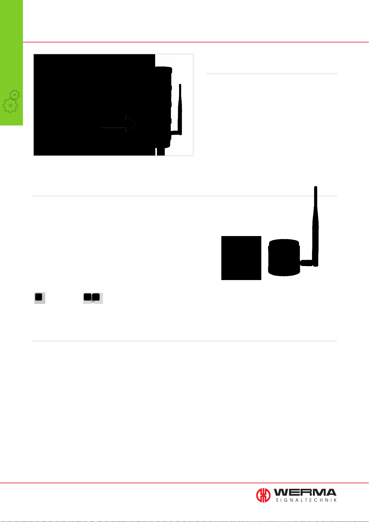
KombiSIGN refl ect consists of
a slave/transmitter and a master/receiver
KombiSIGN reflect: Simple „plug & play“ integration
The two KombiSIGN refl ect elements are synchronised and ready for immediate operation. The signal towers located on the machines
can simply be fi tted with the KombiSIGN refl ect slave/transmitter. A second identical signal tower, which you have previously selected
from WERMA’s KombiSIGN product range, is fi tted with the KombiSIGN refl ect master/receiver and placed within view.
The status of the fi rst tower is then immediately transmitted to the second tower, where it is refl ected one-to-one.
The system uses the 868 MHz (EU) or 915 MHz (North America) frequency band and has a transmission range of up to 300 m
(unobstructed line of sight). The indoor range may be less depending on the characteristics of the building.
26
Page 28
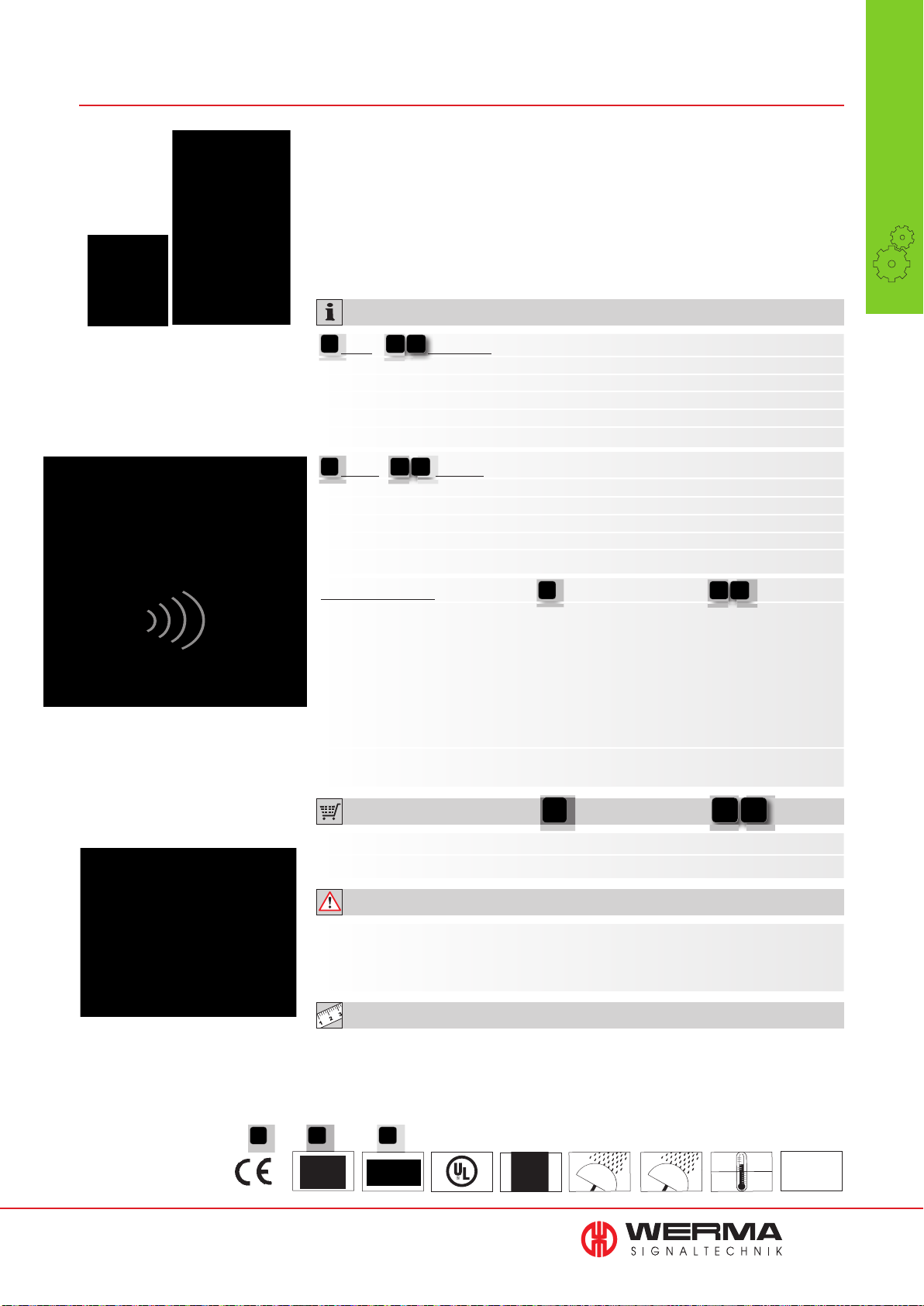
861
KombiSIGN reflect for KombiSIGN 70 and 71
• Simple monitoring of signal
towers out of view
• Signal tower “refl ection” to a
central location
TECHNICAL SPECIFICATIONS:
• No additional wiring costs
• Simple commissioning due to
pre-confi gured modules
Wireless
•
Call Systems
Systems
The slave/transmitter sends the status
directly to the master/receiver, and
reflects the status of the signal tower
installed on the machine
Simple monitoring of
signal towers out of view
Slave / Transmitter
Dimensions (Ø x Height): 70 mm x 65.5 mm
Housing: PC, black
Connection: Bayonet
Operating voltage: 24 V AC/DC
Current consumption: 40 mA
Master / Receiver
Dimensions (Ø x Height): 70 mm x 65.5 mm (without antenna)
Housing: PC, black
Connection: Bayonet
Operating voltage: 24 V DC
Current consumption: 40-900 mA
Wireless connection
ISM frequency: 868 MHz (KombiSIGN 915 MHz
refl ect conforms to the (only for use in
EU’s EN 300220 in North America)
harmonised standard and
can thus be used in all
EU member countries).
Further countries upon request
Transmission range: Up to 300 m (unobstructed line of sight)
Simply fit the KombiSIGN reflect
slave/transmitter to the signal tower
on the machine
ORDER SPECIFICATIONS:
KombiSIGN 70 refl ect 861 840 01 861 840 02
KombiSIGN 71 refl ect 861 640 01 861 640 02
ADDITIONAL INFORMATION:
Please check the wireless frequency. In Europe the version with 868 MHz is used.
In North America the version with 915 MHz is used. Please enquire about use in other
countries.
TECHNICAL DIAGRAMS:
see page 324
861 X40 02
receiver: class 2
See note
on page 347
861 640 0X 861 840 0X
IP 65
IP 54
+50°C
-20°C
PLC
27
Page 29

modular
•
Signal Towers
Page 30
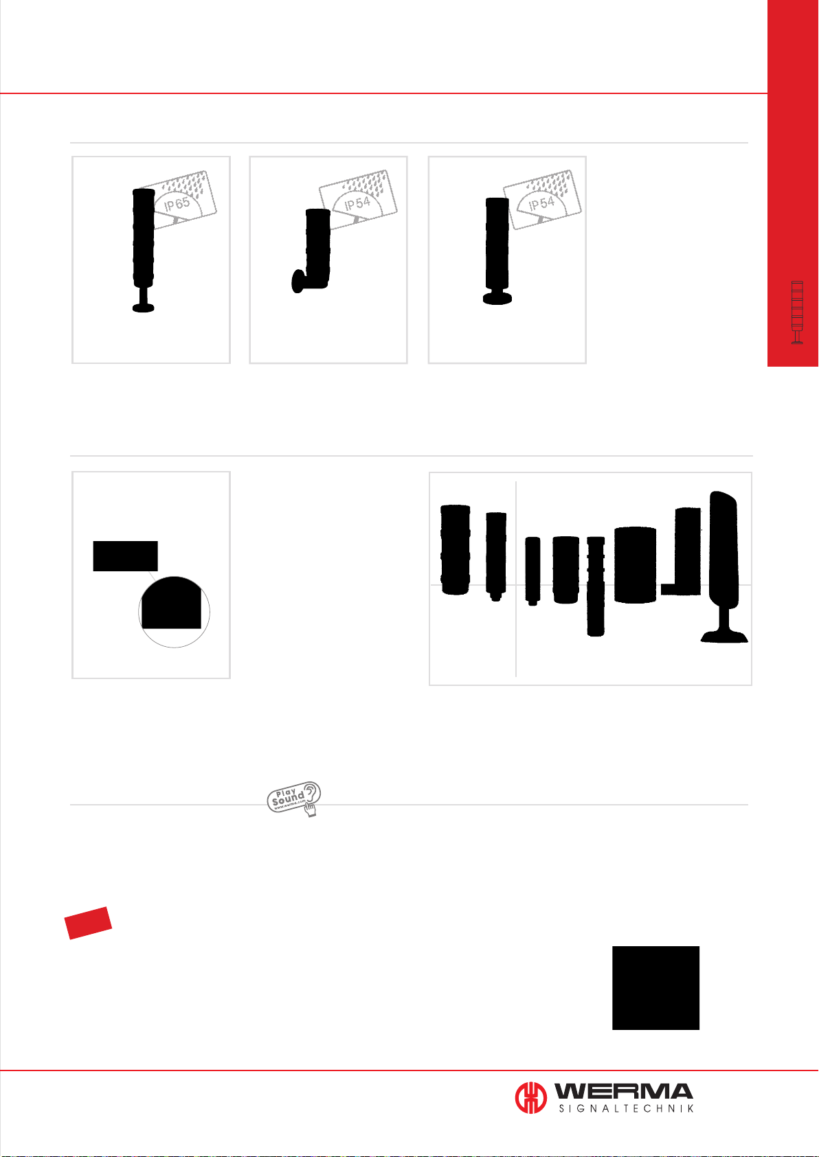
Overview Signal Towers • modular
Modular Signal Towers
KombiSIGN 71
KombiSIGN 70
KombiSIGN 50
modular
•
Signal Towers
IP 65 • Ø 70 mm
Page 31
IP 54 • Ø 70 mm
Page 47
Accessories for
KombiSIGN 50, 70 and 71
Accessories
KombiSIGN 50,70 and 71
Page 67 onwards
IP 54 • Ø 50 mm
Page 61
Size comparison · Signal Towers
modular pre-assembled
KombiSIGN
KombiSIGN 50KOMPAKT37KOMPAKT71deSIGN42FlatSIGN VarioSIGN CleanSIGN
70/71
Sound
The sounds can be played from our website
www.werma.com under the heading „Signal Towers“.
Further Information
Further Information and applications for "Signal Towers" can be
found in the chapter "Systems" beginning on page 11.
TIP
The Signal Devices Site on the internet: www.werma.com
With our ”Configurator“ you can put together a signal tower quickly and easily according to your requirements.
The configurator interactively guides the user through a series of pictures and questions to create an individual
signal tower solution in just a few clicks.
www.werma.com
29
Page 31
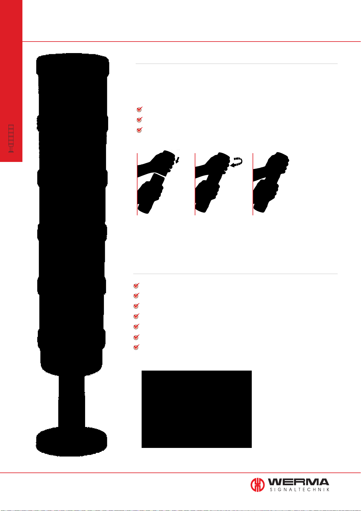
KombiSIGN 70 and 71 Signal Towers
modular
•
KombiSIGN
Signal Towers
Simple operation thanks to bayonet mechanism
WERMA was the first signal beacon manufacturer to
offer a bayonet mechanism allowing elements to be
mechanically and electrically connected within
seconds.
Simple mounting and removal of the elements
New combinations at the twist of a hand
Tool-free bulb change
The advantages at a glance
Signal elements in every common voltage
Modular system allows combination as required
High protection rating IP 54 or IP 65
Wide range of optical and audible elements
LED technology ensures even better visibility
Attention-grabbing light effects (e.g. EVS)
Wide range of terminal elements
30
www.werma.com
Page 32
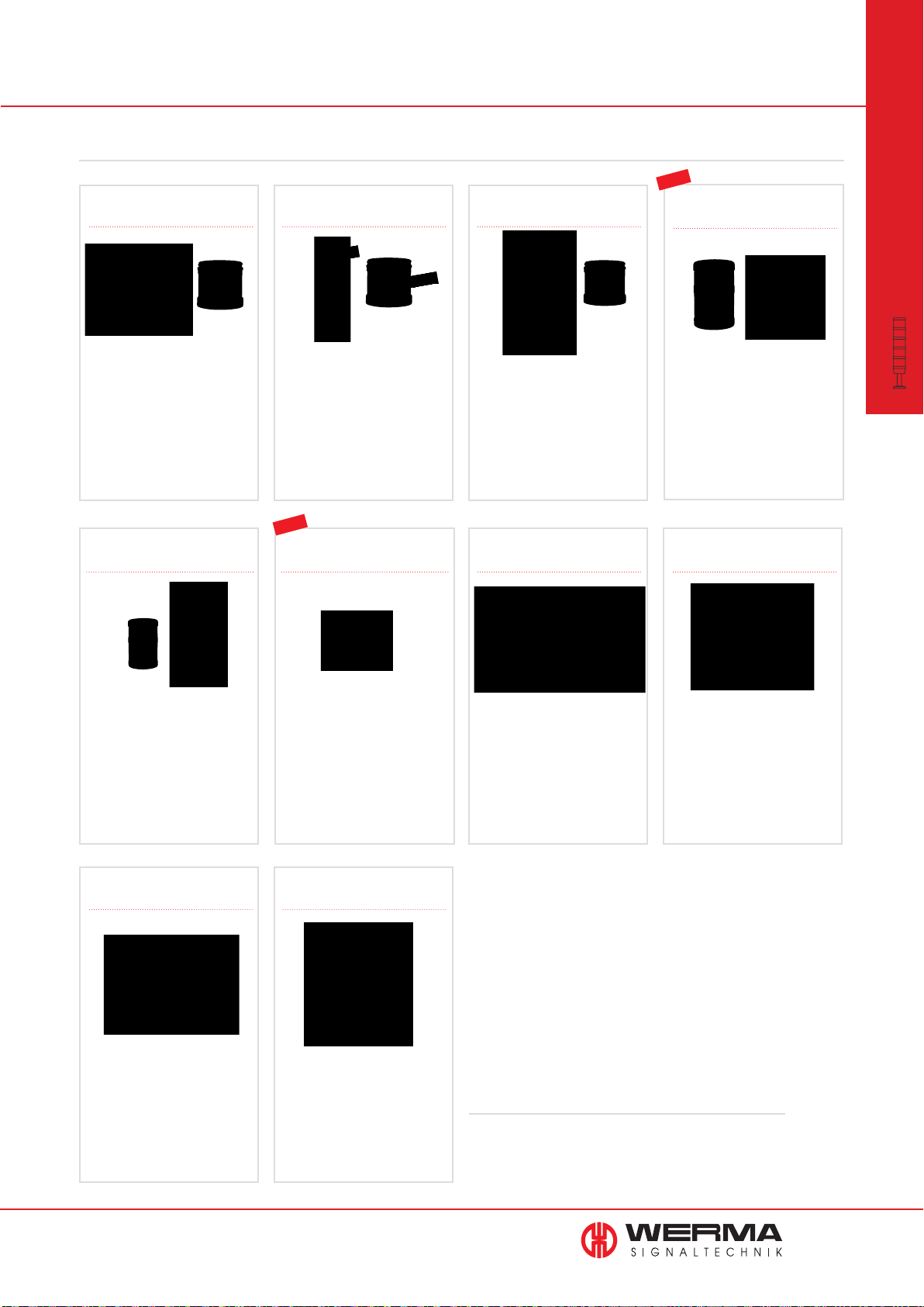
KombiSIGN 71 Signal Tower
The Highlights for KombiSIGN 71
644 LED Permanent light
element ultrabright
• Up to 20 times brighter than
conventional LED elements
• Maximum brightness via
intelligent LED control
See page 35
self-adjusting sound output
644 LED EVS element
• Attention-grabbing flickering
light
• Extremely powerful signal
effect
• Random sequence of light
signals prevents acclimatisation
effect
See page 36
NEW
640 Terminal element M12 640 Terminal element
644 LED Permanent light
element multicolour
• 7 colours in one beacon
• Multiple status warnings can
be signalled by one beacon
• High light intensity
See page 37
with USB Interface
NEW
645 Vocal element
• 102 dB loud vocal element with
excellent tone and sound
quality
• Sound output level can be
triggered externally
See page 40 + 41
646 AS-Interface element645 Siren element with
modular
•
KombiSIGN 71
Signal Towers
• Sound output is automatically
adjusted to the background
noise level
• Warning tone can be heard
without being irritatingly loud
See page 42
Machine Data Collection
Systems (MDC Systems)
• Wireless based machine data
collection
• Monitoring and counting
system for multiple machines
See page 12
• Quick and easy installation
• With practical M12 connector
See page 43
Manual Call Systems
• Improve the efficiency of
production processes your
operation.
• Indicate status conditions and
problems at the touch of a
button.
See page 20
• Direct triggering of signal
tower elements via USB
Interface
• Easy activation
See page 43
• LEDs indicate current status
• 31 or 62 addresses
• Available with standard
or A/B technology
See page 45
Further infomation
Further Information and applications for "KombiSIGN Signal
Towers" can be found in the chapter "Systems" beginning on
page 11.
www.werma.com
31
Page 33
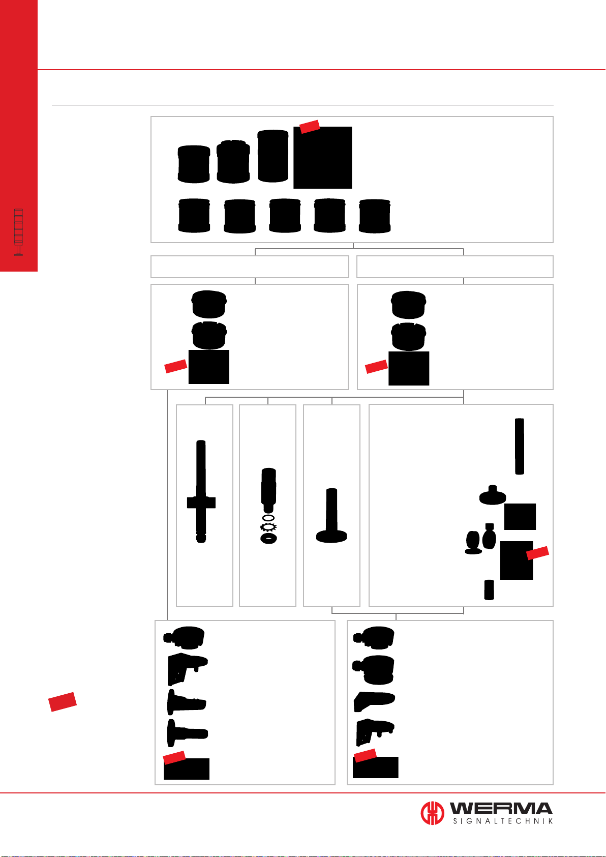
Signal Towers KombiSIGN 71
This is how you can assemble your KombiSIGN 71 signal tower
modular
•
Signal Towers
STEP 1
Select the required optical
or audible elements in the
correct voltage (for details
see page 33).
Many KombiSIGN highlights
KombiSIGN 71
are also available (for details
see page 31).
STEP 2
Select the appropriate
mounting option for your
application.
STEP 3
Select the correct terminal
element for your mounting
option
(for details see page 43).
STEP 4
Where appropriate, select
a base and the desired
tube length (only for tube
mounting) (For details see
page 67).
NEW
Tube with
clamp
Order no.
960 000 18
NEW
Audible Signal Elements
• Buzzer element
• Siren element
• Vocal element
Optical Signal Elements
• (LED) Permanent light
• LED Permanent light ultrabright
• (LED) Flashing light
• LED EVS element
• LED Blinking light
• LED Rotating light
• LED Permanent light element multicolour
Base Mounting Tube Mounting
Terminal element with
CAGE CLAMP
Order no. 640 800 00
Screw terminal
Order no. 640 820 00
Terminal element M12
Order no. 640 850 55
Adaptor for
single hole
mounting
Order no.
960 000 25
®
technology
Base with
integrated
tube
Order no.
975 840 10
NEW
Tube Ø 25 mm, all anodized
Order no.
100 mm long 975 845 10
250 mm long 975 840 25
400 mm long 975 840 40
600 mm long 975 840 60
800 mm long 975 840 80
1000 mm long 975 840 03
Base for Tube, plastic
Order no. 975 840 90
Base for Tube, metal
Order no. 975 840 91
Foldaway Base
Order no. 960 000 30
Foldaway Base
Order no. 960 009 12
Tube Ø 25 mm, plastic, only for
Foldaway Base, 45 mm long
Order no. 960 000 31
Terminal element with
CAGE CLAMP
Order no. 640 810 00
Screw terminal
Order no. 640 830 00
Terminal element M12
Order no. 640 860 55
®
technology
NEW
STEP 5
Where appropriate, select the
bracket and the contact box
(for details see page 67).
TIP
The Signal Devices Site on the
Internet: www.werma.com
With new signal tower
configurator you can put together your own individual signal
tower.
32
www.werma.com
NEW
Contact box for cable exit at side
Order no. 975 840 01
Bracket for base mounting
Order no. 960 000 02
Bracket for 1-sided mounting
Order no. 975 840 85
Bracket for 2-sided mounting
Order no. 975 840 86
Corner fixing bracket
Order no. 960 000 41
NEW
Contact box for cable exit at side
Order no. 975 840 01
Contact box with magnetic base
and cable exit at side
Order no. 975 840 04
Bracket for base mounting
with concealed cable entry
Order no. 960 000 14
Bracket for tube mounting
Order no. 960 000 01
Corner fixing bracket
Order no. 960 000 41
Page 34
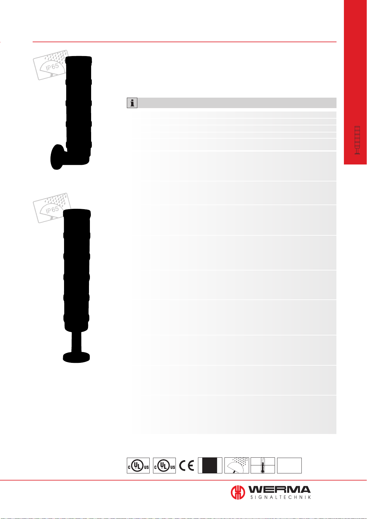
641/644 Optical Signal Elements KombiSIGN 71
KombiSIGN signal tower
with bracket (accessory)
• Signal tower system 70 mm Ø
• Improved illumination
with modular construction
TECHNICAL SPECIFICATIONS:
Dimensions (Ø x Height): 70 mm x 65.5 mm
Lens: PC, transparent
Socket: Bayonet, BA15d, for bulbs max. 5 W
Element seal: Pre-mounted with each module
Protection rating: IP 65
Permanent light element 12-240 V AC/DC
Bulb not included in assembly.
Life duration: Dependent upon the bulbs used
LED Permanent light element 24 V AC/DC 115 V AC 230 V AC
Current consumption: < 30 mA < 20 mA < 20 mA
Life duration: 50,000 hrs
LED Permanent
Current consumption: Max. 195 mA
Life duration: Up to 50,000 hrs
Technical specifi cations see page 35.
light element ultrabright
24 V DC
modular
•
KombiSIGN 71
Signal Towers
Base with tube (accessory)
Flashing light element (Xenon) 24 V DC 115 V AC 230 V AC
Current consumption: 125 mA 22 mA 15 mA
Life duration: 4 x 10
6
fl ashes
Reduced for AS-Interface: 80 mA
Flash frequency:
C.
1 Hz
LED Flashing light element 24 V DC
Current consumption: < 35 mA
Life duration: 50,000 hrs
Flash frequency: C. 1 Hz (Double Flash)
LED EVS* element 24 V AC/DC
Current consumption: 350 mA (red/ yellow) 250 mA (green/clear/blue)
Life duration: 50,000 hrs
* EVS = Enhanced Visibility System
Technical specifi cations see page 36.
LED Blinking light element 24 V AC/DC 115 V AC 230 V AC
Current consumption: 25 mA 25 mA 25 mA
Life duration: 50,000 hrs
Blink frequency: C. 1 Hz
LED Rotating light element 24 V AC/DC
Current consumption: 40 mA
Life duration: 50,000 hrs
Rotation frequency: C. 120 r.p.m.
LED Permanent light element
multicolour 24 V DC
Life duration: 50.000 h
Current consumption: < 120 mA
Possible colours: Red, yellow, green, white, blue, violet, turquoise
Technical specifi cations see page 37.
www.werma.com
643 X10 55
Class 2
See note
on page 347
IP 65
+50°C
-20°C
24 V
PLC
33
Page 35
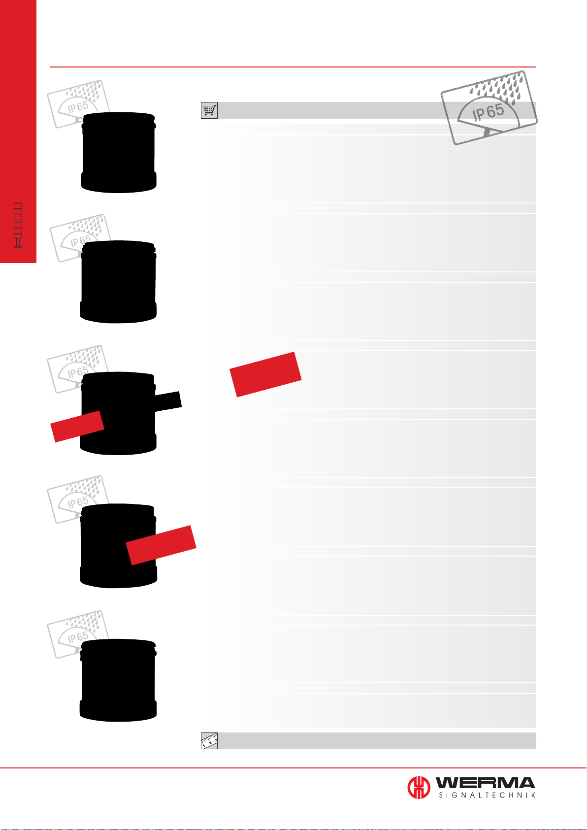
641/644 Optical Signal Elements KombiSIGN 71
modular
•
KombiSIGN 71
Signal Towers
(LED) Permanent/Flashing element
Permanent light element,
clear with info
ORDER SPECIFICATIONS OPTICAL ELEMENTS:
Permanent light element 12-240 V AC/DC
red 641 100 00
green 641 200 00
yellow 641 300 00
clear 641 400 00
blue 641 500 00
Bulb not included in assembly. Accessories see page 67.
LED Permanent light element 24 V AC/DC 115 V AC 230 V AC
red 644 100 75 644 100 67 644 100 68
green 644 200 75 644 200 67 644 200 68
yellow 644 300 75 644 300 67 644 300 68
clear 644 400 75 644 400 67 644 400 68
blue 644 500 75 644 500 67 644 500 68
LED Permanent light element ultrabright 24 V DC
red 644 180 55
green 644 280 55
yellow 644 380 55
clear 644 480 55
blue 644 580 55
Flashing light (Xenon) 24 V DC (ASI) 24 V DC 115 V AC 230 V AC
red 643 110 55 643 100 55 643 100 67 643 100 68
green 643 210 55 643 200 55 643 200 67 643 200 68
Compare the prices
yellow 643 310 55 643 300 55 643 300 67 643 300 68
clear 643 410 55 643 400 55 643 400 67 643 400 68
blue 643 510 55 643 500 55 643 500 67 643 500 68
and advantages of
an LED Flashing light
Patent
approved
LED EVS element
LED element
Life duration
up to 50,000 hrs
LED Flashing light element 24 V DC
red 644 120 55
green 644 220 55
yellow 644 320 55
clear 644 420 55
blue 644 520 55
LED EVS element 24 V DC
red 644 140 55
green 644 240 55
yellow 644 340 55
clear 644 440 55
blue 644 540 55
LED Blinking light element 24 V AC/DC
115 V AC
230 V AC
red 644 110 75 644 110 67 644 110 68
green 644 210 75 644 210 67 644 210 68
yellow 644 310 75 644 310 67 644 310 68
clear 644 410 75 644 410 67 644 410 68
blue 644 510 75 644 510 67 644 510 68
LED Rotating light element 24 V AC/DC
red 644 130 75
green 644 230 75
yellow 644 330 75
clear 644 430 75
blue 644 530 75
LED Permanent light element multicolour 24 V DC
multicolour 644 450 55
LED element (multicolour)
34
www.werma.com
Further voltages on request.
TECHNICAL DIAGRAMS: see page 309
Page 36
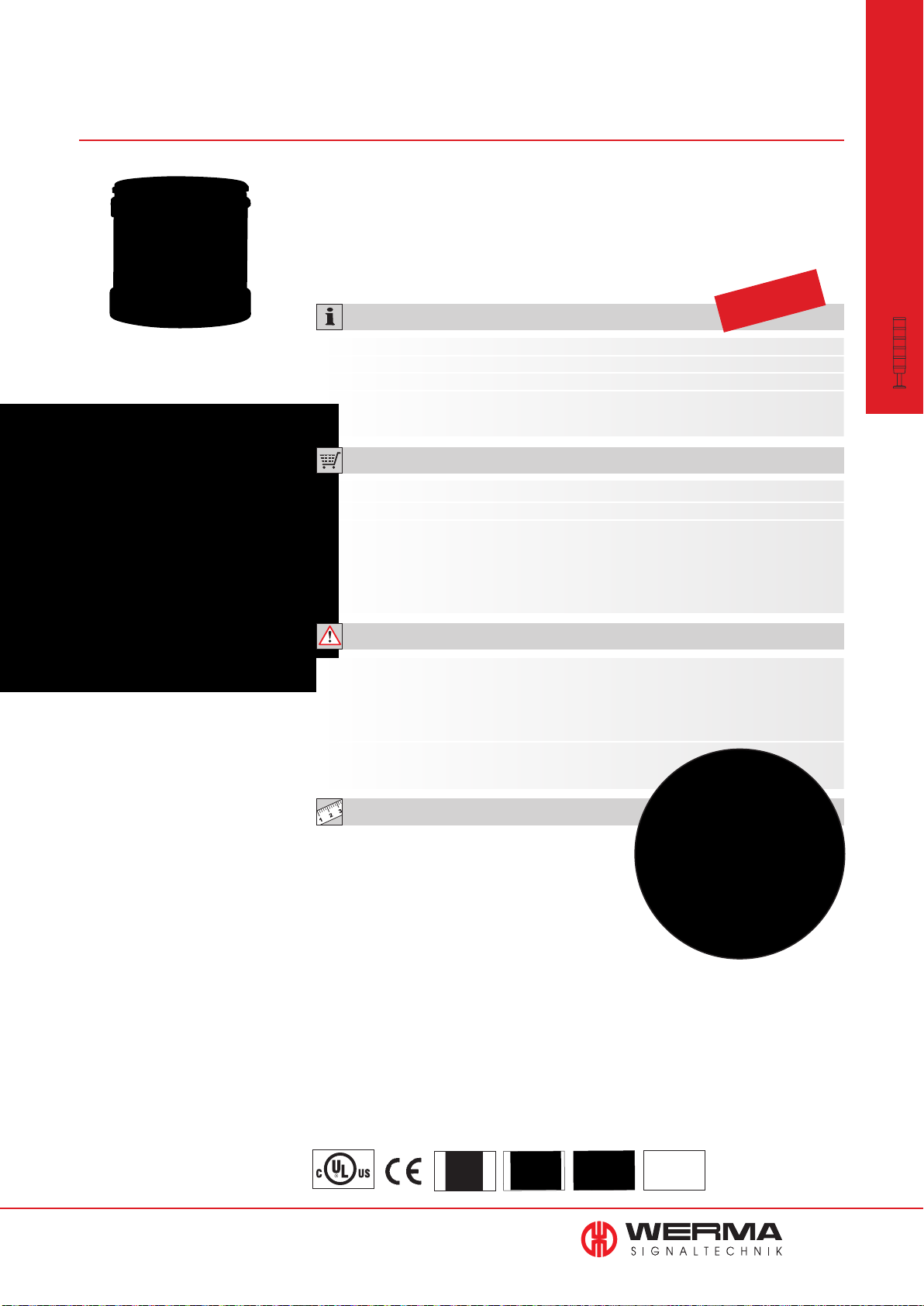
644 LED Permanent Light Element
ultrabright for KombiSIGN 71
• Up to 20 times brighter than
conventional LED elements
• Maximum brightness via
intelligent LED control
• Extremely good visibility -
even in direct sunlight
TECHNICAL SPECIFICATIONS:
Dimensions (Ø x Height): 70 mm x 65.5 mm
Lens: PC, transparent
Seal: Pre-mounted with each element
Number of modules
possible: 5, with 2-sided bracket max. 10
ORDER SPECIFICATIONS:
Voltage 24 V DC
Current consumption Max. 195 mA
red 644 180 55
green 644 280 55
yellow 644 380 55
clear 644 480 55
blue 644 580 55
Life duration
up to 50,000 hrs
modular
•
KombiSIGN 71
Signal Towers
Maximum brightness via
intelligent LED control
ADDITIONAL INFORMATION:
Sophisticated triggering
Thanks to its sophisticated triggering, the innovative LED element “ultrabright” is up to
20 times brighter than conventional LED elements - making it almost certainly the brightest
permanent light that the world of signalling technology currently has to offer.
Further information can be found in the chapter
”General Information“ beginning on page 366.
TECHNICAL DIAGRAMS:
see page 309
The high level of brightness
guarantees good visibility -
even in direct sunlight
www.werma.com
See note
on page 347
IP65
+50°C
-20°C
PLC
35
Page 37
644
LED EVS* Element for KombiSIGN 71
modular
•
KombiSIGN 71
Signal Towers
Patent
approved
• Attention-grabbing fl ickering light
• Extremely powerful signal effect
• Random sequence of light signals
• For signalling extremely hazardous
situations and the need for
immediate action
prevents acclimatisation effect
TECHNICAL SPECIFICATIONS:
Dimensions (Ø x Height): 70 mm x 65 mm
Lens: PC, transparent
Seal: Pre-mounted with each element
Number of modules
possible: 5, with 2-sided bracket max. 10
ORDER SPECIFICATIONS:
Voltage 24 V DC 24 V DC
Current consumption 350 mA 250 mA
red 644 140 55 -
green - 644 240 55
yellow 644 340 55 -
clear - 644 440 55
blue - 644 540 55
Life duration
up to 50,000 hrs
Integrated into the KombiSIGN
Signal Towers, the LED EVS*
Element generates a highly
attention-grabbing signal
ADDITIONAL INFORMATION:
* EVS = Enhanced Visibility System
Further Information can be found in the chapter ”General Information“ on page 352.
Please note the photosensitive epilepsy warning on page 352.
TECHNICAL DIAGRAMS:
see page 309
36
www.werma.com
See note
on page 347
IP 65
+50°C
-20°C
PLC
Page 38
644 LED Permanent Light Element
multicolour for KombiSIGN 71
The LED permanent light element multicolour offers a life
duration of up to 50,000 hrs
• Seven colours in one beacon
• Multiple status warnings can be
signalled by one beacon
• Different colours can be triggered
via the pins in the terminal element
TECHNICAL SPECIFICATIONS:
Dimensions Terminal Elements (Ø x Height): 70 mm x 65.5 mm
Lens: PC, transparent
Light effect: LED permanent
Possible Colours: Red, yellow, green, white, blue, violet, turquoise
Seal: Pre-mounted with each element
Number of modules possible: Max. 3 (including multicolour element)
ORDER SPECIFICATIONS:
Voltage
Current consumption
LED permanent light multicolour
• Positive and negative control logic
• The three basic colours (red/
yellow/green) can be triggered
using only two PLC outputs
• High light intensity
Life duration
up to 50,000 hrs
24 V DC
< 120 mA
644 450 55
ADDITIONAL INFORMATION:
modular
•
KombiSIGN 71
Signal Towers
7 colours in one beacon: red,
yellow, green, white, blue, violet
and turquoise
The Multicolour Element can
be combined with up to 2
additional signal elements
Simple external activation via the pins in the terminal element.
TECHNICAL DIAGRAMS:
see page 309
4
3
2
5
0 GND
(-)
1
www.werma.com
See note
on page 347
86 g
IP 65
+50°C
-20°C
PLC
37
Page 39
645 Audible Elements KombiSIGN 71
modular
•
KombiSIGN 71
Signal Towers
Bracket (accessory)
• Audible element sound output up
to 105 dB
TECHNICAL SPECIFICATIONS:
Dimensions (Ø x Height):
Lens:
Element seal:
Protection rating:
See below
PC
Pre-mounted with each module
IP 65
• Plays back pre-recorded music
fi les or customised audio fi les
Life duration
up to 5,000 hrs
(Order no. 645 830 55 = IP 40)
Buzzer element 24 V AC/DC 115 V AC 230 V AC
Current consumption: 25 mA
Dimensions (Ø x Height): 70 mm x 72 mm
Sound output: 85 dB
Number/Tone type:
Siren element 24 V DC
Current consumption: 150 mA
Dimensions (Ø x Height): 70 mm x 79 mm
Sound output: 105 dB
Number/Tone type:
Further Information: No UL approval
Continuous or pulse tone
Continuous tone alternating
Three tier signal tower with vocal
element and tube with integrated
base (accessory)
Multi-functional Siren 24 V AC/DC 115 V AC 230 V AC
Current consumption: 80 mA 40 mA 40 mA
Dimensions (Ø x Height): 70 mm x 72 mm
Sound output: 100 dB,
Number/Tone type:
Multi-functional Siren, 24 V DC
with external control
Current consumption: 80 mA
Dimensions (Ø x Height): 70 mm x 72 mm
Sound output: 100 dB,
Number/Tone type:
Further Information: No UL approval
Tone triggering: 7 diff. tones can be triggered externally
Siren element with 24 V DC
self-adjusting sound output
Technical specifi cations see page 42.
Vocal element 24 V DC
Technical specifi cations see page 40.
High output vocal element
NEW
Further Information:
Technical specifi cations see page 41.
24 V DC
adjustable sound output
8 tones adjustable
adjustable sound output
Number of tones dependent on the number of optical elements
No UL approval
ORDER SPECIFICATIONS AUDIBLE ELEMENTS: see next page
38
www.werma.com
See note
on page 347
IP 65
+50°C
-20°C
24 V
PLC
Page 40
Audible element
Siren element with
self-adjusting sound output
ORDER SPECIFICATIONS AUDIBLE ELEMENTS:
Buzzer element 24 V AC/DC 115 V AC 230 V AC
645 800 75 645 800 77 645 800 68
Siren element 24 V DC
645 830 55
Multi-functional Siren 24 V AC/DC 115 V AC 230 V AC
645 820 75 645 820 67 645 820 68
Multi-functional Siren, 24 V DC
with external control 645 850 55
Siren element with 24 V DC
self-adjusting sound output 645 810 55
Vocal element 24 V DC (max. 88 dB)
645 840 55
High output vocal element 24 V DC (max. 102 dB)
NEW
645 860 55
modular
•
KombiSIGN 71
Signal Towers
Vocal element
with up to 88 dB
NEW
High output vocal element
with up to 102 dB
TECHNICAL DIAGRAMS:
see page 309 onwards
www.werma.com
39
Page 41
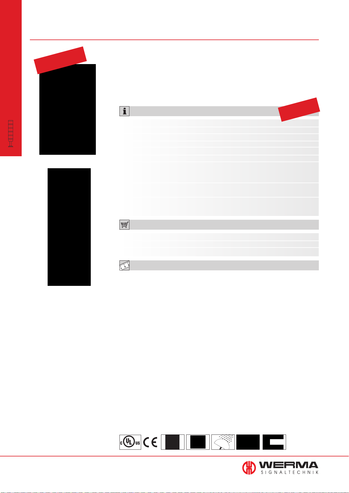
645
Vocal Element for
KombiSIGN 71
modular
•
KombiSIGN 71
Signal Towers
German utility
model approved
• Plays customer-specific audio files
in mp3 format (signal tones, music
or spoken text)
• Enables clear instructions to be
given in a range of foreign languages
TECHNICAL SPECIFICATIONS:
Dimensions (Ø x Height): 70 mm x 111 mm
Housing: PC
Number of signal elements: Max. 4 additional signal elements possible
Sound output: Adjustable, up to 88 dB
File Transfer: Via USB connection and provided software
Possible data format: Mp3 and wav files
Number of sequences: 15 files can be remotely triggered depending on the
number of signal elements used or one sequence with
max. 50 files
Suitable for: Windows 2000 SP 4, Windows XP, Windows Vista,
Windows 7
Assembly: Vocal element,
USB connection cable and software
• Outstanding tonal and sound
quality
• Easy transfer of audio files and
simple operation
• Setting of individual playlists and
playback modi possible
Life duration
up to 5,000 hrs
The vocal element can
be combined with up to
4 signal elements
ORDER SPECIFICATIONS:
Voltage 24 V DC
Current consumption < 500 mA
Vocal element 645 840 55
TECHNICAL DIAGRAMS:
see page 310
40
www.werma.com
See note
on page 347
184 g
IP 65
+50°C
max 88 dB
-20°C
Page 42
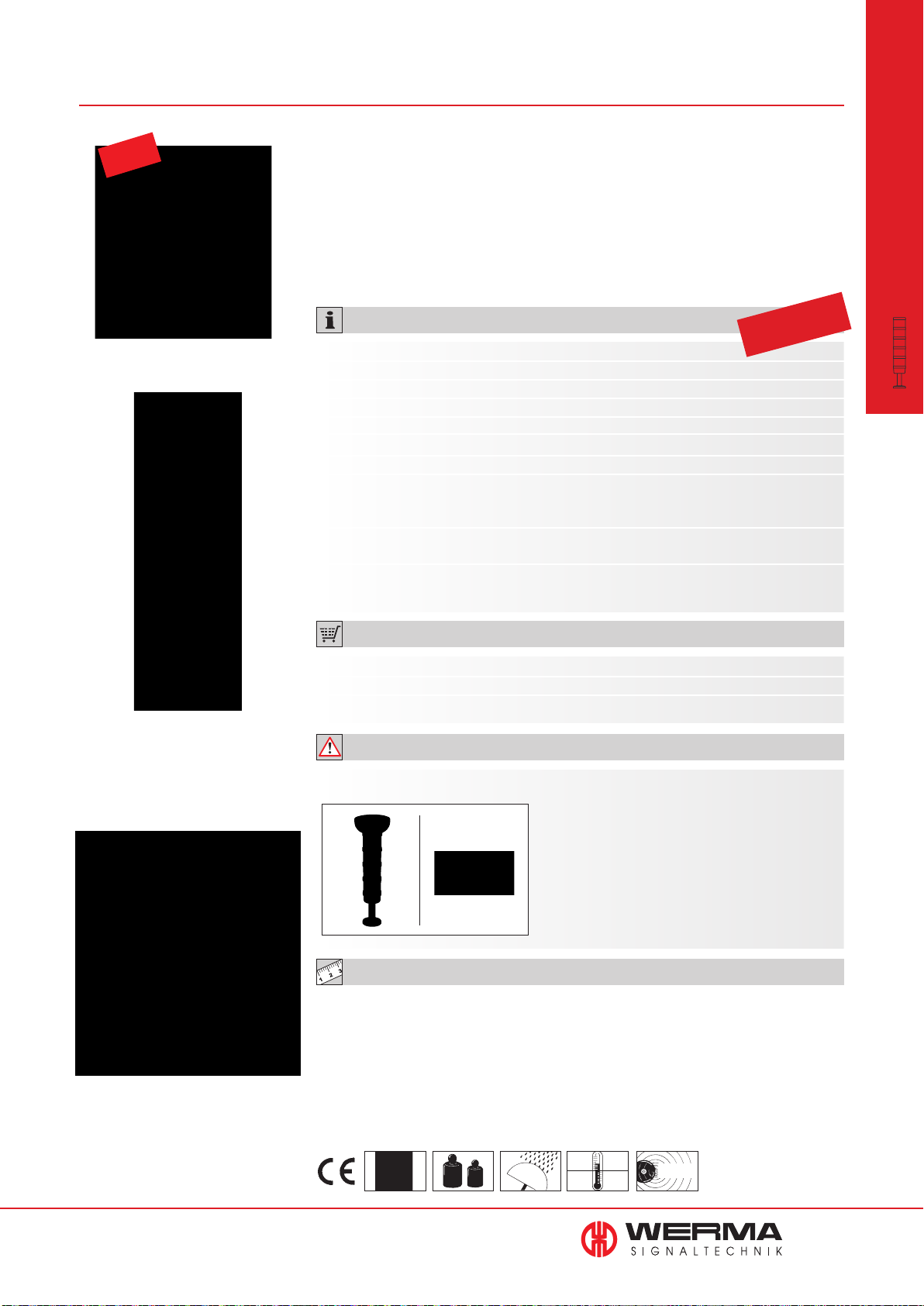
645 Vocal Element for KombiSIGN 71
NEW
• 102 dB high output vocal element
with excellent tone and sound quality
• Plays customer-specific audio
files (signal tones, music and
• Sound output level can be
triggered externally
• Creation of individual playlists
and playback modes possible
spoken text)
• Easy transfer of audio files and
simple operation
TECHNICAL SPECIFICATIONS:
Dimensions (Ø x Height): 125 mm x 118 mm
Housing: PC/ABS Blend
Lens: PC
Number of signal elements: Max. 4 additional signal elements possible
Sound output: Adjustable, up to 102 dB
File Transfer: Via USB connection and provided software
Possible data format: Mp3 and wav files
Number of sequences: 15 files can be remotely triggered depending
on the number of signal elements used or one
sequence with max. 50 files
Suitable for: Windows 2000 service pack 4, Windows XP,
Windows Vista, Windows 7, Windows 8
Assembly: Vocal element, USB connection cable
and software
Life duration
up to 5,000 hrs
modular
•
KombiSIGN 71
Signal Towers
The vocal element can
be combined with up to
4 signal elements
ORDER SPECIFICATIONS:
Voltage 24 V DC
Current consumption ≤ 400 mA
Vocal element 645 860 55
ADDITIONAL INFORMATION:
Further installation examples:
To ensure IP protection it is recommended
that the vocal element is fitted with the
sound outlet facing downwards.
Optimum distribution of sound is thus
ensured.
TECHNICAL DIAGRAMS:
see page 310
User-friendly software ensures
easy transfer of audio files
and simple operation
www.werma.com
See note
on page 347
610 g
IP 65
+50°C
102 dB
-20°C
41
Page 43

645
Siren Element with self-adjusting sound
output for KombiSIGN 71
modular
•
KombiSIGN 71
Signal Towers
Patent
approved
• Automatic sound output adjustment between 80 and 100 dB
• Continual measurement of the
ambient noise level
TECHNICAL SPECIFICATIONS:
Dimensions (Ø x Height): 70 mm x 110 mm
Housing: PC
Tone type: Pulse tone
Tone frequency: 2.5 KHz
Sound output: 80 dB - max. 100 dB
• Sound output is c. 5 dB louder
than the background noise level
• Ideal for applications with
changing ambient sound levels
Life duration
up to 5,000 hrs
Loud enough
yet
not disturbing!
ORDER SPECIFICATIONS:
Voltage 24 V DC
Current consumption < 150 mA
Siren element 645 810 55
ADDITIONAL INFORMATION:
The siren element adjusts its sound output through continual measurement of the
ambient noise level. The emitted tone is c. 5 dB louder than the background noise level.
The warning signal can always be heard without being irritatingly loud for
people in the sounder’s vicinity.
The siren element can be
combined with up to
4 signal elements
42
www.werma.com
TECHNICAL DIAGRAMS:
see page 310
See note
on page 347
125 g
IP 65
+50°C
-20°C
max100 dB
PLC
Page 44
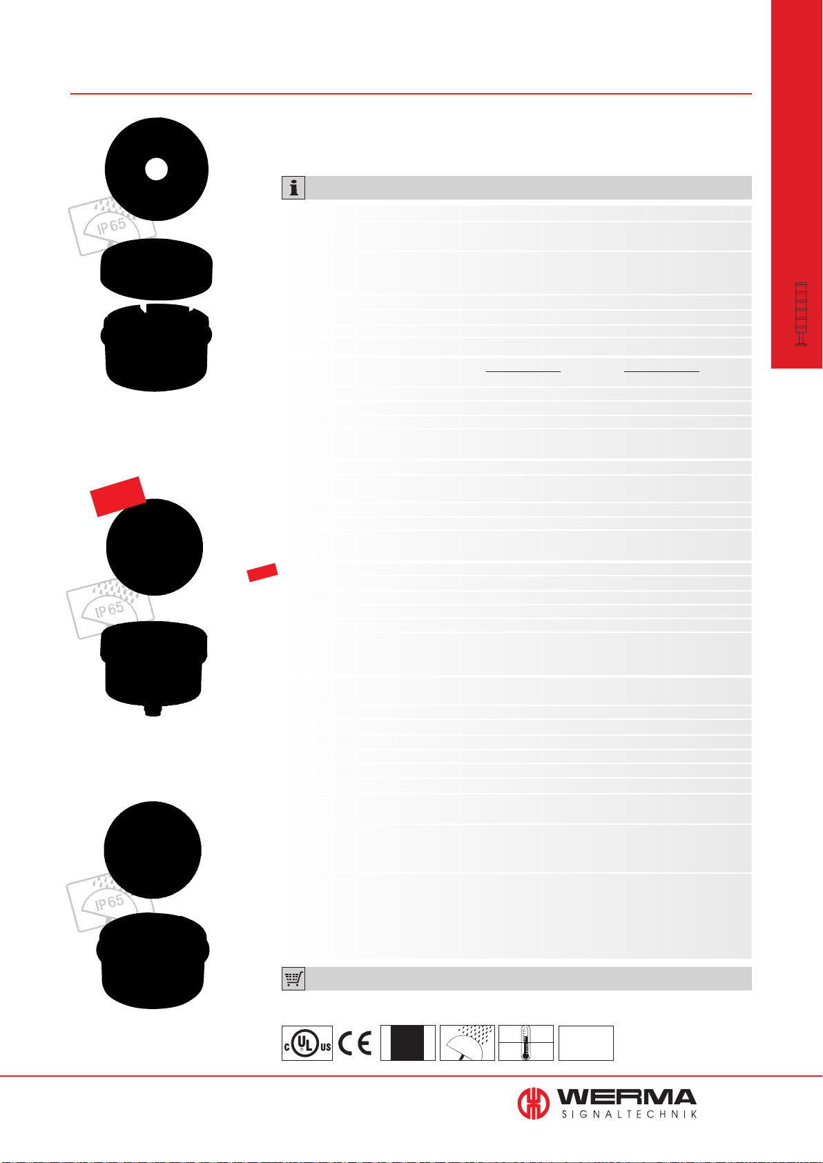
640 Terminal Elements for KombiSIGN 71
Screw terminal with cap
NEW
• Bayonet locking mechanism enables quick and easy essembly of
• The ideal solution for every
installation
the signal tower
TECHNICAL SPECIFICATIONS:
Dimensions (Ø x Height): See below
Housing: Terminal element: PA fi breglass, high-impact
Cap: PC
Fixing: Base mounting
Tube mounting, for tube Ø 25 mm
Bracket mounting (accessory)
Cable entry: Cable diameter max. 14 mm
Element seal: Pre-mounted with each module
Protection rating: IP 65
Number of modules possible: Max. 5
Tube mounting Base mounting
Screw terminal
Dimensions (Ø x Height): 70 mm x 42,5 mm 70 mm x 42,5 mm
Connection: Screw terminal max. 2.5 mm
Voltage: 12-240 V AC/DC 12-240 V AC/DC
Incl. cap Incl. cap and seal
CAGE CLAMP
®
technology
(see picture page 44)
Dimensions (Ø x Height): 70 mm x 42,5 mm 70 mm x 42,5 mm
Connection: CAGE CLAMP
®
technology max. 2.5 mm
Voltage: 12-240 V AC/DC 12-240 V AC/DC
Incl. cap Incl. cap and seal
2
modular
•
KombiSIGN 71
Signal Towers
2
Terminal element with practical
M12 connection socket in base
Terminal element M12
NEW
Dimensions (Ø x Height): 70 mm x 56 mm 70 mm x 50 mm
Connection: M12 connector (8 pole)
Voltage: 12-24 V DC 12-24 V DC
Current carrying capacity: ≤ 2 A ≤ 2 A
Incl. cap Incl. cap and seal
No UL approval No UL approval
Terminal element with
USB Interface No UL approval -
Dimensions (Ø x Height): 70 mm x 36 mm
Fixing: Tube mounting (accessory)
Connection: Via USB
Voltage: Terminal element: Via USB (5 V DC)
Voltage: 24 V DC
Current carrying cap. ∑ Imax: 90 mA at 24 V
Assembly: Assembly includes installation software, drivers,
handbook and USB connection cable (length 1.8 m)
Suitable for: Windows 2000 service pack 4, Windows XP,
Windows Vista or Windows 7. Also for Windows Server
und Windows CE operating systems
• Direct triggering of signal tower elements via USB Interface
• Actuation via DLL (Dynamic Link Library) or VCP (Virtual-COM-Port)
• Simple integration into any customer-specifi c software
• No additional power supply or Hardware necessary
• Up to fi ve signal towers with a maximum of fi ve elements each can be connected
Direct triggering of the signal tower
elements via USB Interface
www.werma.com
ORDER SPECIFICATIONS:
640 8X0 00
x = 0,1,2,3
See note
on page 347
see next page
IP 65
+50°C
-20°C
24 V
PLC
43
Page 45
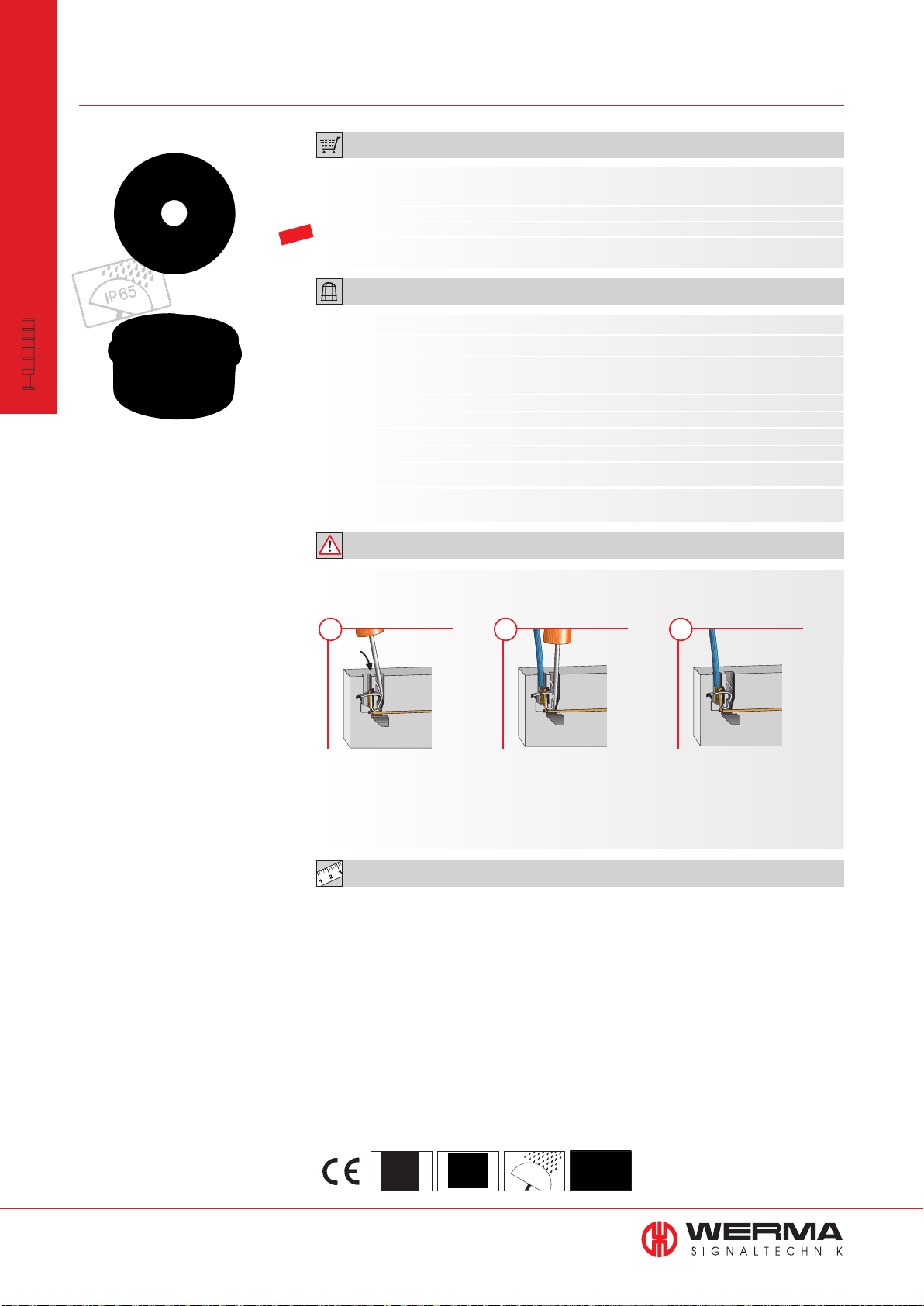
640
Terminal Elements for KombiSIGN 71
ORDER SPECIFICATIONS:
modular
•
KombiSIGN 71
Signal Towers
Tube mounting Base mounting
Screw terminal 640 830 00 640 820 00
CAGE CLAMP
Terminal element M12 640 860 55 640 850 55
NEW
Terminal element with USB interface 640 840 00 -
®
640 810 00 640 800 00
ACCESSORIES:
Base with integrated tube
Base for tube (metal)
Tube Ø 25 mm, Aluminium eloxiert
100 mm long
250 mm long
400 mm long
600 mm long
800 mm long
1000 mm long
Suitable accessories can be found on page 67.
975 840 10
975 840 91
975 845 10
975 840 25
975 840 40
975 840 60
975 840 80
975 840 03
ADDITIONAL INFORMATION:
Terminal elements with CAGE CLAMP
guaranteeing a secure and reliable contact.
®
technology enable leads to be quickly and easily wired,
1 2 3
Insert screwdriver at a slight
angle into opening as far
as possible.
CAGE CLAMP® is a registered trademark of WAGO Kontakttechnik GmbH.
Open spring-loaded clamp with
the help of the screwdriver and
insert wire as far as possible
TECHNICAL DIAGRAMS:
see page 308
Remove screwdriver the wire is fi rmly
clamped.
44
www.werma.com
See note
on page 347
170 g
IP 65
+50°C
-20°C
Page 46
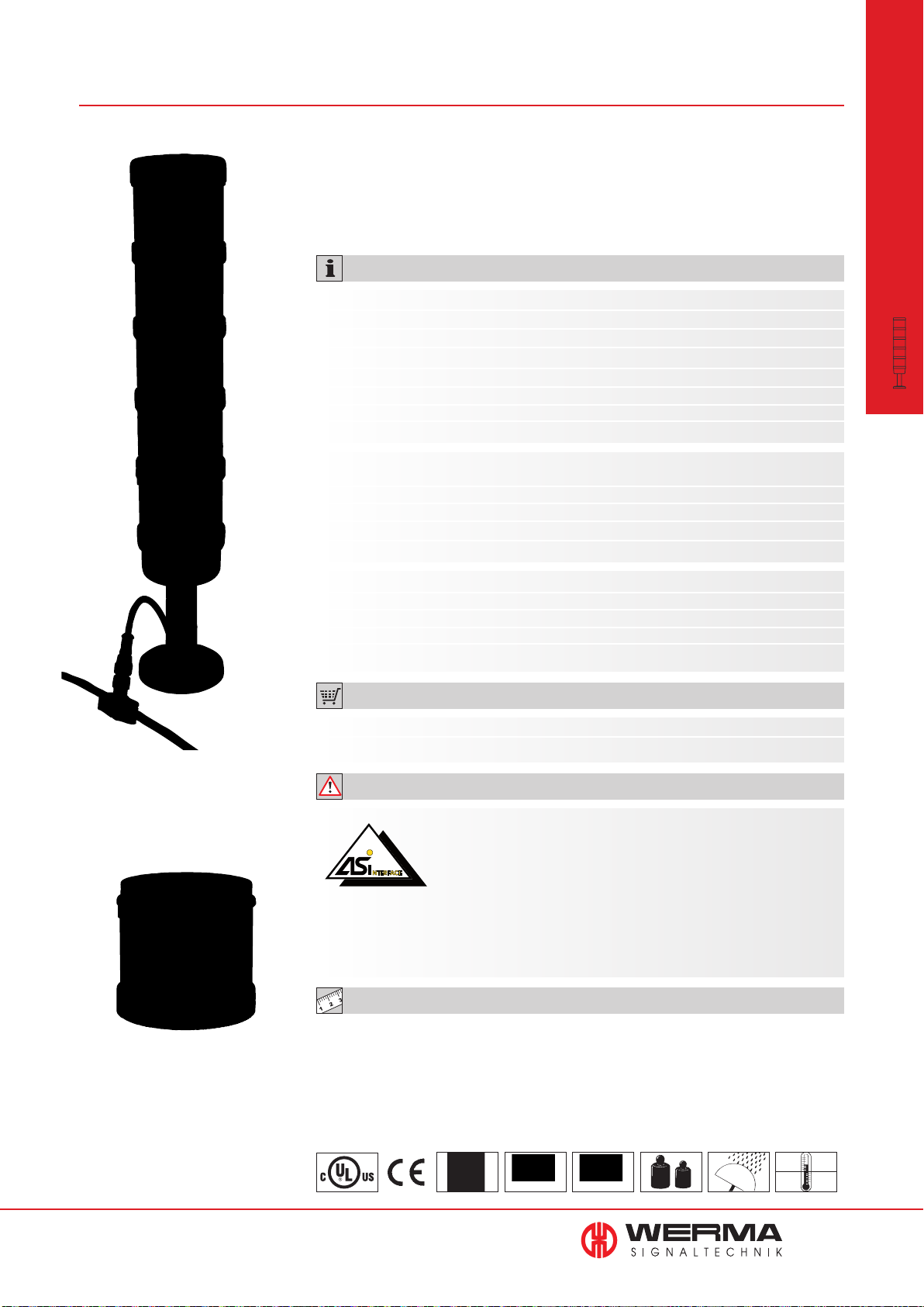
646 AS-Interface Element for KombiSIGN 71
• LEDs indicate current status
• 31 or 62 addresses
• Available with standard or
A/B technology
• Voltage supply switchable from
internal bus supply to additional
external voltage supply
• With addressing socket
TECHNICAL SPECIFICATIONS:
Standard Slave A/B-Slave
Number of addresses: Max. 31 Max. 62
Number of signal elements: Max. 4 Max. 3
IO-Code: 8
ID-Code: F
ID2-Code: N/A E
Outputs: 4 semiconductor relays 3 semiconductor relays
Approved in accordance with: Spec. V 3.0 Spec. V 3.0
Specif. Power supply
AS-Interface Element: Via bus conduction
Operating voltage: 18.5 V … 31.6 V according to the AS-Interface specification
Reverse battery protection: Integrated
Watchdog: Integrated
Additional external voltage: 24 V DC
With internal add. voltage With external add. voltage
Current carrying cap. Σ Imax: 200 mA 200 mA per signal element
Current consumption max: 210 mA ≤ 50 mA
Voltage at signal element: 20 V … 30 V DC 24 V +/- 10%
Short circuit/overload protect
ion: Integrated Pre-fuse M 1.6 A
8
HEX
A
HEX
HEX
HEX
HEX
modular
•
KombiSIGN 71
Signal Towers
Cable not included in assembly
LEDs display the
current status
ORDER SPECIFICATIONS:
AS-Interface Element Standard Slave A/B-Slave
646 830 55 646 810 55
ADDITIONAL INFORMATION:
The KombiSIGN Signal Tower 71 with AS-Interface Element are capable of total communication: Through simple integration
of an AS-Interface Element the actuators are connected to the
networking system Actuator-Sensor-Interface - this considerably
reduces complex wiring. The necessary power supply (supply
via bus or external) can be selected with a switch. This element is
mounted as the first tier of the individual signal tower directly on top of the terminal
element. (Further Information see page 351).
TECHNICAL DIAGRAMS:
see page 311
Class 2
See note
on page 347
Standard Slave
Approval No. 66301
A/B-Slave
Approval No. 66202
77 g
IP 65
+50°C
-20°C
www.werma.com
45
Page 47
KombiSIGN 70 Signal Tower
The Highlights for KombiSIGN 70
modular
•
KombiSIGN 70
Signal Towers
843 LED Permanent light
element ultrabright
• Up to 20 times brighter than
conventional LED elements
• Maximum brightness via
intelligent LED control
See page 50
self-adjusting sound output
843 LED EVS element
• Attention-grabbing flickering
light
• Extremely powerful signal
effect
• Random sequence of light
signals prevents acclimatisation
effect
See page 51
NEW
840 Terminal element M12
843 LED Permanent light
element multicolour
• 7 colours in one beacon
• Multiple status warnings can be
signalled by one beacon
• High light intensity
See page 52
840 AS-Interface element844 Siren element with
NEW
844 Vocal element
• 102 dB loud vocal element with
excellent tone and sound
quality
• Sound output level can be
triggered externally
See page 55 + 56
• Sound output is automatically
adjusted to the background
noise level
• Warning tone can be heard
without being irritatingly loud
See page 57
Machine Data Collection
Systems (MDC Systems)
• Wireless based machine data
collection
• Monitoring and counting
system for multiple machines
See Page 12
• Quick and easy installation
• With practical M12 connector
See Seite 58
Manual Call Systems
• Improve the efficiency of
production processes your
operation
• Indicate status conditions and
problems at the touch of a
button
See Page 20
• LEDs indicate current status
• 31 or 62 addresses
• Available with standard
or A/B technology
See page 59
Further Information
Further Information and applications for "KombiSIGN Signal
Towers" can be found in the chapter "Systems" beginning on
page 11.
46
www.werma.com
Page 48
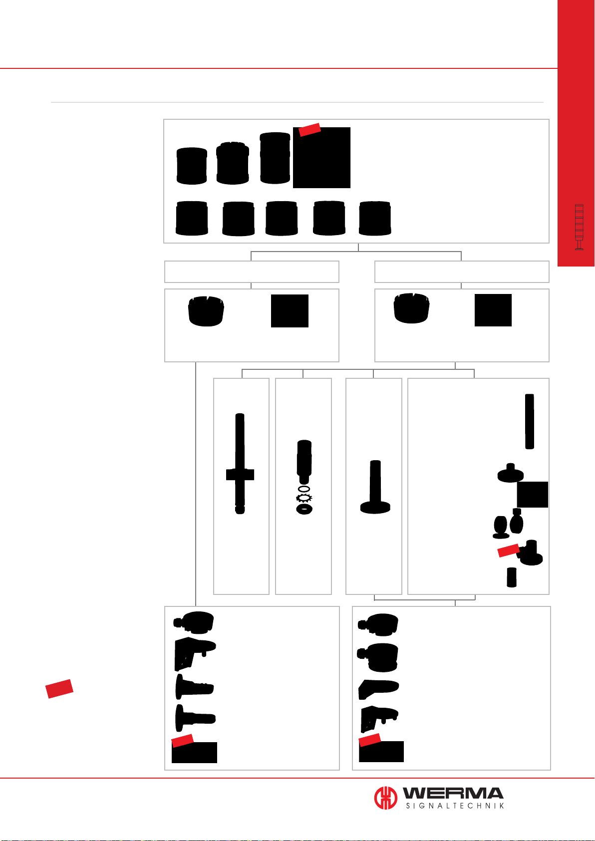
This is how you can assemble your KombiSIGN 70 signal tower
STEP 1
Select the required optical
or audible elements in the correct
voltage.
Many KombiSIGN highlights
are also available (for details
see page 46).
NEW
Audible Signal Elements
• Buzzer element
• Siren element
• Vocal element
Optical Signal Elements
• (LED) Permanent light
• LED Permanent light ultrabright
• (LED) Flashing light
• LED EVS element
• LED Blinking light
• LED Rotating light
• LED Permanent light element multicolour
modular
•
KombiSIGN 70
Signal Towers
STEP 2
Select the appropriate mounting
option for your application.
STEP 3
Select the correct terminal element
for your mounting option.
STEP 4
Where appropriate, select a base
and the desired length (only for
tube mounting).
Base Mounting Tube Mounting
Terminal element
for base mounting
Order no. 840 085 00
Tube with
clamp
Order no.
960 000 18
Terminal element M12
Order no. 840 850 55
Adaptor for
single hole
mounting
Order no.
960 000 25
Terminal element
for tube mounting
Order no. 840 080 00
Base with
integrated
tube
Order no.
975 840 10
Terminal element M12
Order no. 840 860 55
Tube Ø 25 mm, all anodized
Order no.
100 mm long 975 845 10
250 mm long 975 840 25
400 mm long 975 840 40
600 mm long 975 840 60
800 mm long 975 840 80
1000 mm long 975 840 03
Base for Tube, plastic
Order no. 975 840 90
Base for Tube, metal
Order no. 975 840 91
Foldaway Base
Order no. 960 000 30
Foldaway Base
Order no. 960 009 12
Tube Ø 25 mm, plastic, only for
Foldaway Base, 45 mm long
Order no. 960 000 31
NEW
STEP 5
Where appropriate, select the
bracket and the contact box.
TIP
The Signal Devices Site on the
Internet: www.werma.com
With our new signal tower
configurator you can put together
your own individual signal tower.
www.werma.com
NEW
Contact box for cable exit at side
Order no. 975 840 01
Bracket for base mounting
Order no. 960 000 02
Bracket for 1-sided mounting
Order no. 975 840 85
Bracket for 2-sided mounting
Order no. 975 840 86
Corner fixing bracket
Order no. 960 000 41
NEW
Contact box for cable exit at side
Order no. 975 840 01
Contact box with magnetic base and
cable exit at side
Order no. 975 840 04
Bracket for base mounting
with concealed cable entry
Order no. 960 000 14
Bracket for tube mounting
Order no. 960 000 01
Corner fixing bracket
Order no. 960 000 41
47
Page 49
840/843
Optical Signal Elements for KombiSIGN 70
modular
•
KombiSIGN 70
Signal Towers
Bracket (accessory)
• Clear signalling, even in
unfavourable light conditions
• LED light elements have an
extremely long life and low
current consumption
TECHNICAL SPECIFICATIONS:
Dimensions (Ø x Height): 70 mm x 65.5 mm
Lens: PC, transparent
Socket: Bayonet, BA15d, for bulb max. 5 W
Element seal: Pre-mounted with each module
Protection rating: IP 54
Permanent light element 12-240 V AC/DC
Bulb not included in assembly
Life duration: Dependent upon the bulbs used
LED Permanent light element 24 V AC/DC 115 V AC 230 V AC
Current consumption: < 30 mA < 20 mA < 20 mA
Life duration: 50,000 hrs
LED Permanent light element
ultrabright 24
Current consumption: Max. 195 mA
Life duration: Up to 50,000 hrs
Technical specifi cations see page 51.
Flashing light element (Xenon) 24 V DC 115 V AC 230 V AC
Current consumption: 125 mA 22 mA 15 mA
Life duration: 4 x 10
Reduced for AS-Interface: 80 mA
Flash frequency:
C.
V DC
1 Hz
6
fl ashes
Tube mounting (accessory)
LED Flashing light element 24 V DC
Current consumption: < 35 mA
Life duration: 50,000 hrs
Flash frequency: C. 1 Hz (Double Flash)
LED EVS* element 24 V DC
Current consumption: 350 mA (red/ yellow) 250 mA (green/clear/blue)
Life duration: 50,000 hrs
* EVS = Enhanced Visibility System
Technical specifi cations see page 51.
LED Blinking light element 24 V AC/DC 115 V AC 230 V AC
Current consumption: 25 mA 25 mA 25 mA
Life duration: 50,000 hrs
Blink frequency: C. 1 Hz
LED Rotating light element 24 V AC/DC
Current consumption: 40 mA
Life duration: 50,000 hrs
Rotation frequency: C. 120 r.p.m.
LED Permanent Light Element
multicolour 24 V DC
Life duration: 50,000 hrs
Current consumption: < 120 mA
Possible colours: Red, yellow, green, white, blue, violet, turquoise
Technical specifi cations see page 52.
842 X10 55
Class 2
See note
on page 347
IP 54
+50°C
-20°C
24 V
PLC
48
www.werma.com
Page 50
ORDER SPECIFICATIONS OPTICAL ELEMENTS:
(LED) Permanent/
Flashing light element
Permanent light element,
clear with info
Patent
approved
LED EVS element
Permanent light element 12-240 V AC/DC
red 840 100 00
green 840 200 00
yellow 840 300 00
clear 840 400 00
blue 840 500 00
Bulb not included in assembly. Accessories see page 67.
LED Permanent light element 24 V AC/DC 115 V AC
230 V AC
red 843 100 55 843 100 67 843 100 68
green 843 200 55 843 200 67 843 200 68
yellow 843 300 55 843 300 67 843 300 68
clear 843 400 55 843 400 67 843 400 68
blue 843 500 55 843 500 67 843 500 68
LED Permanent light element ultrabright 24 V DC
red 843 180 55
green 843 280 55
yellow 843 380 55
clear 843 480 55
blue 843 580 55
Flashing light (Xenon) 24 V DC
(ASI)
24 V DC 115 V AC
230 V AC
red 842 110 55 842 100 55 842 100 67 842 100 68
green 842 210 55 842 200 55 842 200 67 842 200 68
Compare the prices
yellow 842 310 55 842 300 55 842 300 67 842 300 68
clear 842 410 55 842 400 55 842 400 67 842 400 68
blue 842 510 55 842 500 55 842 500 67 842 500 68
and advantages of
an LED Flashing light
LED Flashing light element 24 V DC
red 843 120 55
green 843 220 55
yellow 843 320 55
clear 843 420 55
blue 843 520 55
modular
•
KombiSIGN 70
Signal Towers
Life duration
up to 50,000 hrs
LED element
LED element multicolour
LED EVS element 24 V DC
red 843 140 55
green 843 240 55
yellow 843 340 55
clear 843 440 55
blue 843 540 55
LED Blinking light element 24 V AC/DC 115 V AC 230 V AC
red 843 110 55 843 110 67 843 110 68
green 843 210 55 843 210 67 843 210 68
yellow 843 310 55 843 310 67 843 310 68
clear 843 410 55 843 410 67 843 410 68
blue 843 510 55 843 510 67 843 510 68
LED Rotating light element 24 V AC/DC
red 843 130 55
green 843 230 55
yellow 843 330 55
clear 843 430 55
blue 843 530 55
LED Permanent light element multicolour 24 V DC
multicolour 843 450 55
Further voltages on request.
TECHNICAL DIAGRAMS:
see page 318 onwards
www.werma.com
49
Page 51
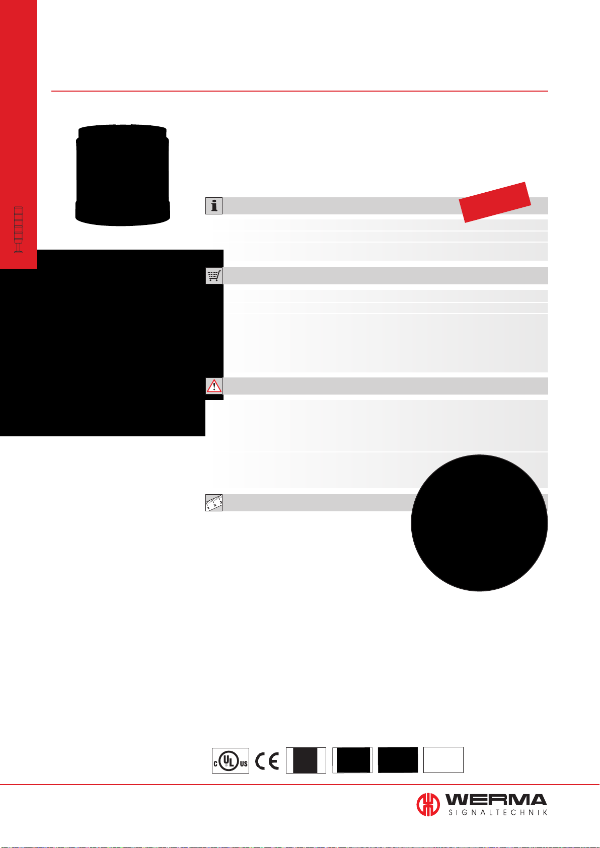
843 LED Permanent Light Element
ultrabright for KombiSIGN 70
modular
•
KombiSIGN 70
Signal Towers
• Up to 20 times brighter than
conventional LED elements
• Extremely good visibility -
even in direct sunlight
• Shock-proof and vibration-resistant
• Maximum brightness via intelligent
LED control
• Low current consumption and
maintenance-free
TECHNICAL SPECIFICATIONS:
Dimensions (Ø x Height): 70 mm x 65.5 mm
Lens: PC, transparent
Seal: Pre-mounted with each element
ORDER SPECIFICATIONS:
Voltage 24 V DC
Current consumption Max. 195 mA
red 843 180 55
green 843 280 55
yellow 843 380 55
clear 843 480 55
blue 843 580 55
ADDITIONAL INFORMATION:
Life duration
up to 50,000 hrs
Maximum brightness via
intelligent LED control
Sophisticated triggering
Thanks to its sophisticated triggering, the innovative LED element “ultrabright” is up to
20 times brighter than conventional LED elements - making it almost certainly the brightest
permanent light that the world of signalling technology currently has to offer.
Further Information can be found in the chapter
”General Information“ beginning on page 354.
TECHNICAL DIAGRAMS:
see page 319
The high level of brightness
guarantees good visibility -
even in direct sunlight
50
www.werma.com
Class 2
See note
on page 347
IP 54
+50°C
-20°C
PLC
Page 52
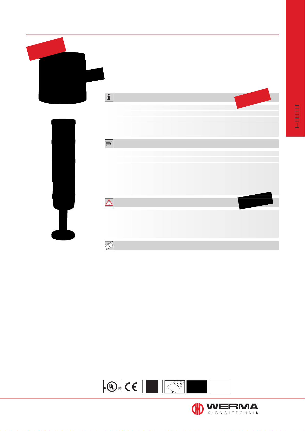
843
LED EVS* Element for KombiSIGN 70
Patent
approved
• Attention-grabbing fl ickering light
• Extremely powerful signal effect
• Random sequence of light signals
• For signalling extremely
hazardous situations and the
need for immediate action
prevents acclimatisation effect
TECHNICAL SPECIFICATIONS:
Dimensions (Ø x Height): 70 mm x 65.5 mm
Lens: PC, transparent
Seal: Pre-mounted with each element
Number of modules
possible: 5, with 2-sided bracket max. 10
ORDER SPECIFICATIONS:
Voltage 24 V
Current consumption
red 843 140 55 green - 843 240 55
yellow 843 340 55 clear - 843 440 55
blue - 843 540 55
350 mA 250 mA
DC 24 V DC
Life duration
up to 50,000 hrs
modular
•
KombiSIGN 70
Signal Towers
Integrated into the KombiSIGN
Signal Towers, the EVS*
LED Element generates a highly
attention-grabbing signal
ADDITIONAL INFORMATION:
* EVS = Enhanced Visibility System or Enhanced Visibility System
Further Information can be found in the chapter ”General Information“ on page 352.
Please note the photosensitive epilepsy warning on page 352.
TECHNICAL DIAGRAMS:
see page 319
www.werma.com
Class 2
See note
on page 347
IP 54
+50°C
-20°C
PLC
51
Page 53
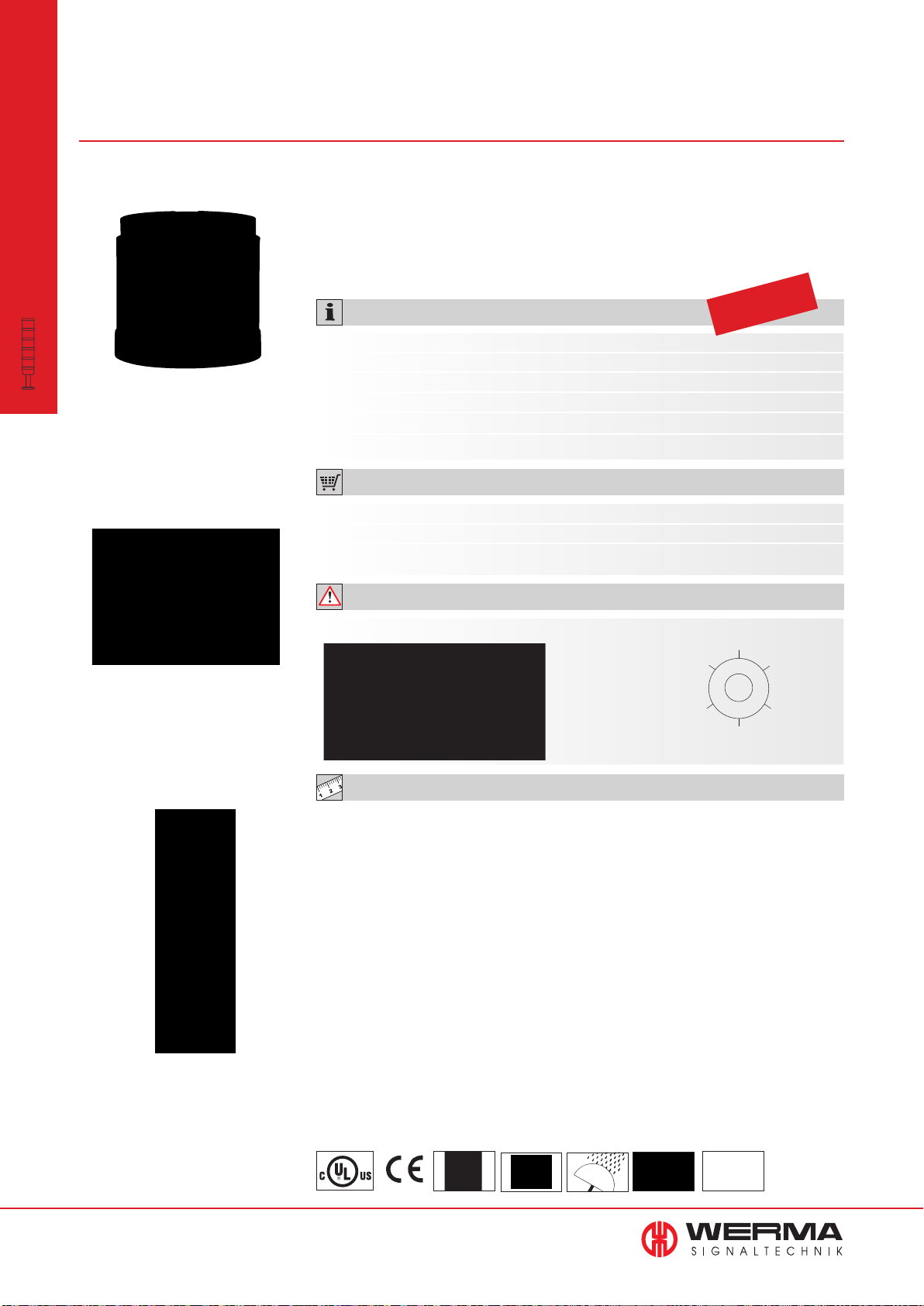
843 LED Permanent Light Element
multicolour for KombiSIGN 70
modular
•
KombiSIGN 70
Signal Towers
The LED permanent light
element multicolour offers a
life duration of up to 50,000 hrs
• Seven colours in one beacon
• Multiple status warnings can be
signalled by one beacon
• Different colours can be triggered
via the pins in the terminal element
TECHNICAL SPECIFICATIONS:
Dimensions (Ø x Height): 70 mm x 65.5 mm
Lens: PC, transparent
Colours: LED permanent
Possible Colours: Red, yellow, green, white, blue, violet, turquoise
Seal: Pre-mounted with each element
Number of modules possible: Max. 3 (including Multicolour element)
• Positive and negative control logic
• The three basic colours (red/
yellow/green) can be triggered
using only two PLC outputs
• High light intensity
Life duration
up to 50,000 hrs
ORDER SPECIFICATIONS:
Voltage 24 V DC
Current consumption < 120 mA
LED permanent light multicolour 843 450 55
ADDITIONAL INFORMATION:
7 colours in one beacon: red,
yellow, green, white, blue, violet
and turquoise
The Multicolour Element can be
combined with up to 2 additional
signal elements
Simple external activation via the pins in the terminal element.
TECHNICAL DIAGRAMS:
see page 319
4
3
2
5
0 GND
(-)
1
52
www.werma.com
See note
on page 347
86 g
IP 54
+50°C
-20°C
PLC
Page 54
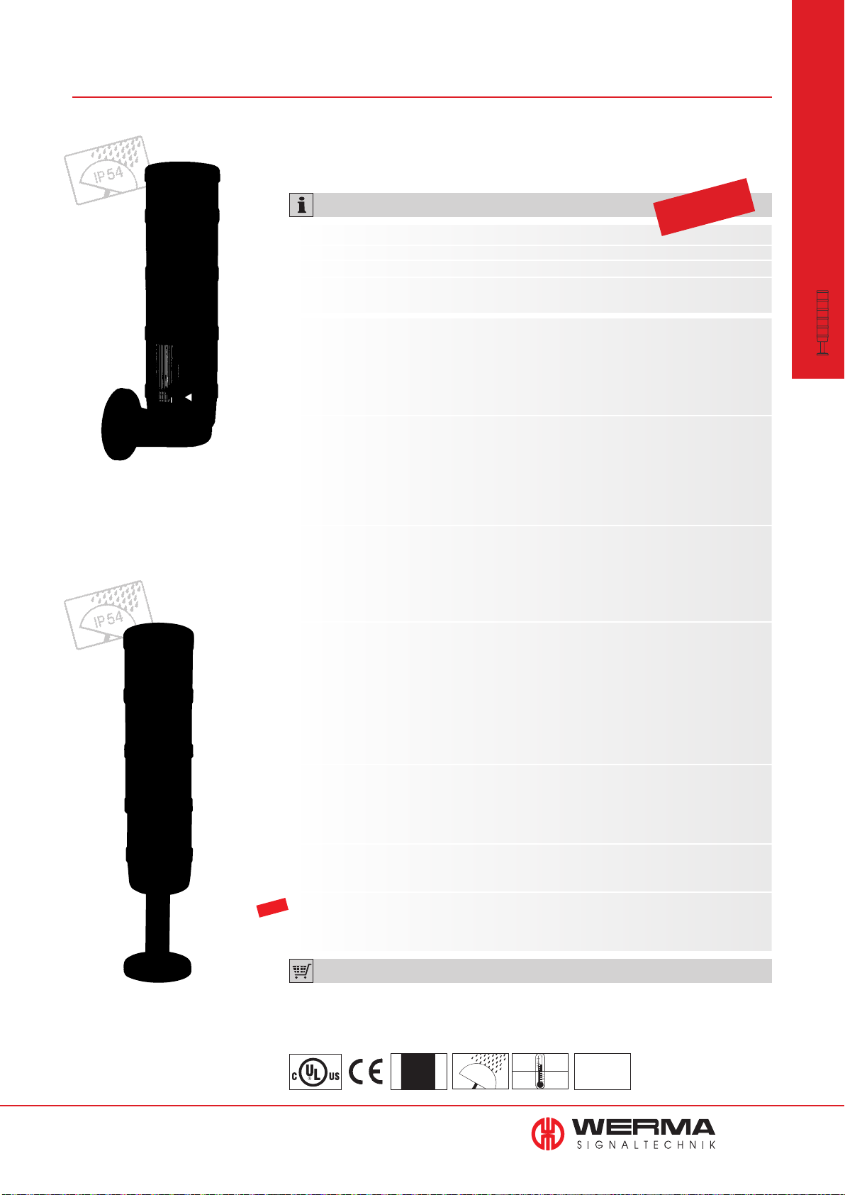
844
Audible Elements for KombiSIGN 70
• Audible element sound output
up to 105 dB
modular
•
Bracket (accessory)
TECHNICAL SPECIFICATIONS:
Life duration
up to 5,000 hrs
Dimensions (Ø x Height): see below
Lens:
PC/ABS
Element seal: Pre-mounted with each module
Protection rating: IP 54
(Order no. 844 123 55 = IP 40)
Buzzer element 24 V AC/DC 115 V AC 230 V AC
Current consumption: 25 mA
Dimensions (Ø x Height): 70 mm x 72 mm
Sound output: 85 dB
Number/Tone type: Continuous or pulse tone
Siren element 24 V DC
Current consumption: 150 mA
Dimensions (Ø x Height): 70 mm x 79 mm
Sound output: 105 dB
Number/Tone type: Continuous tone alternating
Further Information: No UL approval
Multi-functional Siren 24 V AC/DC 115 V AC 230 V AC
Current consumption: 80 mA 40 mA 40 mA
Dimensions (Ø x Height): 70 mm x 72 mm
Sound output: 100 dB, adjustable sound output
Number/Tone type: 8 different tones
KombiSIGN 70
Signal Towers
Tube mounting (accessory)
Multi-functional Siren, 24 V DC
with external control
Current consumption: 80 mA
Dimensions (Ø x Height): 70 mm x 72 mm
Sound output: 100 dB, adjustable sound output
Number/Tone type: Number of tones dependent on the number of optical
elements
Tone triggering: 7 diff. tones can be triggered externally
Siren element with 24 V DC
self-adjusting sound output
Technical specifi cations see page 57.
Vocal element 24 V DC (max. 88 dB)
Technical specifi cations see page 55.
High output vocal element 24 V DC (max. 102 dB)
NEW
Further Information: No UL approval
Technical specifi cations see page 56.
ORDER SPECIFICATIONS AUDIBLE ELEMENTS:
see next page
See note
on page 347
+50°C
IP 54
-20°C
24 V
PLC
www.werma.com
53
Page 55
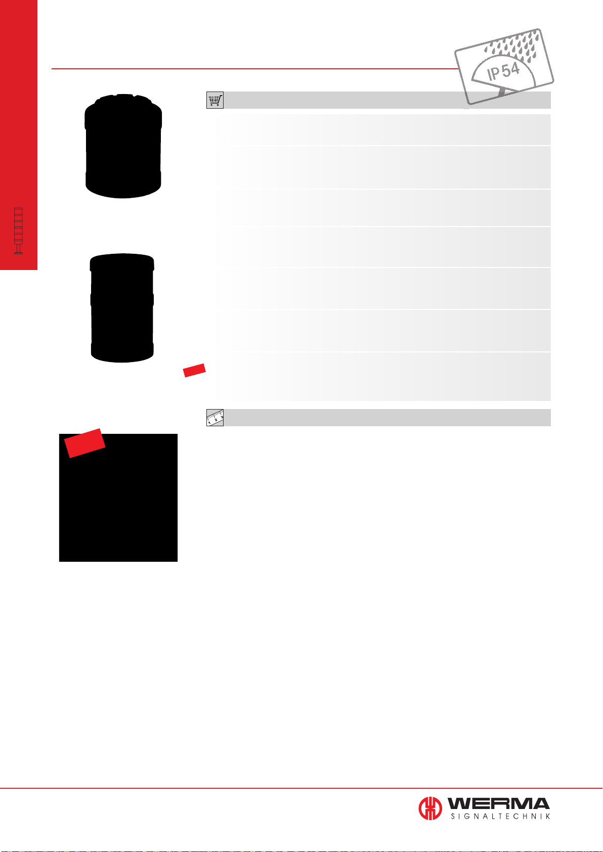
844 Audible Elements KombiSIGN 70
modular
•
KombiSIGN 70
Signal Towers
Siren element
844 123 55
ORDER SPECIFICATIONS AUDIBLE ELEMENTS:
Buzzer element 24 V AC/DC 115 V AC 230 V AC
844 118 55 844 118 67 844 118 68
Siren element 24 V DC
844 123 55
Multi-functional Siren 24 V AC/DC 115 V AC 230 V AC
844 126 55 844 126 67 844 126 68
Multi-functional Siren, 24 V DC
with external control 844 126 95
Siren element with 24 V DC
self-adjusting sound output 844 810 55
Vocal element 24 V DC (max. 88 dB)
844 840 55
Vocal element
with up to 88 dB
NEW
High output vocal element
with up to 102 dB
High output vocal element 24 V DC (max. 102 dB)
NEW
844 860 55
TECHNICAL DIAGRAMS:
see page 319 onwards
54
www.werma.com
Page 56
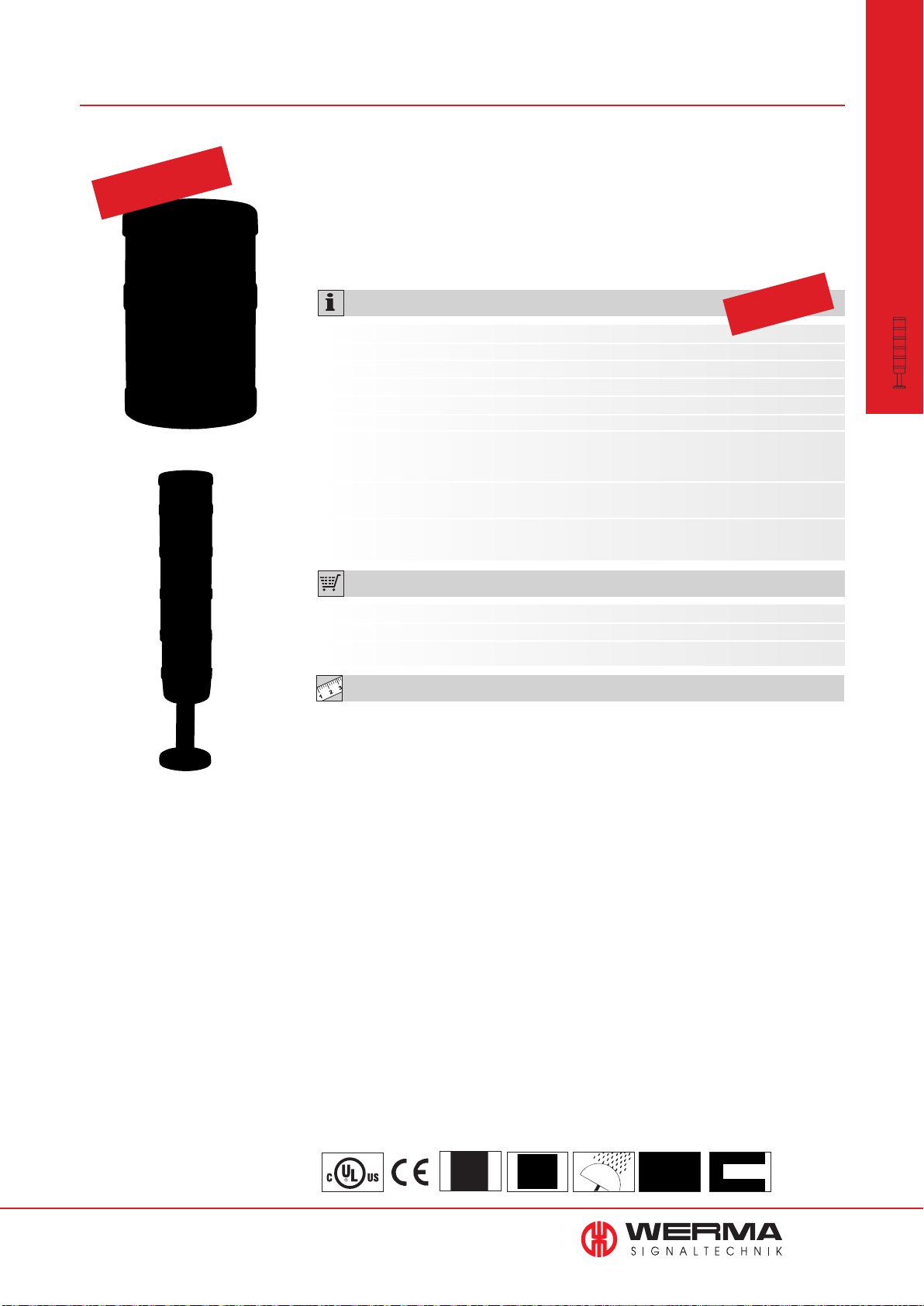
844 Vocal
Element for KombiSIGN 70
German utility
model approved
• Plays customer-specific audio
files in mp3 format (signal tones,
music or spoken text)
• Enables clear instructions to be
given in a range of foreign
languages
TECHNICAL SPECIFICATIONS:
Dimensions (Ø x Height): 70 mm x 110 mm
Material: PC
Number of signal elements: Max. 4 additional signal elements possible
Sound output: Adjustable, up to 88 dB
File Transfer: Via USB connection and provided software
Possible data format: Mp3 and wav files
Number of sequences: 15 files can be remotely triggered depending on the
number of signal elements used or one sequence with
max. 50 files
Suitable for: Windows 2000 service pack 4, Windows XP,
Windows Vista, Windows 7
Assembly: Vocal Element,
USB connection cable and software
• Outstanding tonal and
sound quality
• Easy transfer of audio files and
simple operation
• Setting of individual playlists and
playback modi possible
Life duration
up to 5,000 hrs
ORDER SPECIFICATIONS:
modular
•
KombiSIGN 70
Signal Towers
The vocal element can
be combined with up to
4 signal elements
Vocal element 24 V DC
Current consumption < 500 mA
Vocal element 844 840 55
TECHNICAL DIAGRAMS:
see page 319
www.werma.com
See note
on page 347
260 g
IP 54
+50°C
max 88 dB
-20°C
55
Page 57
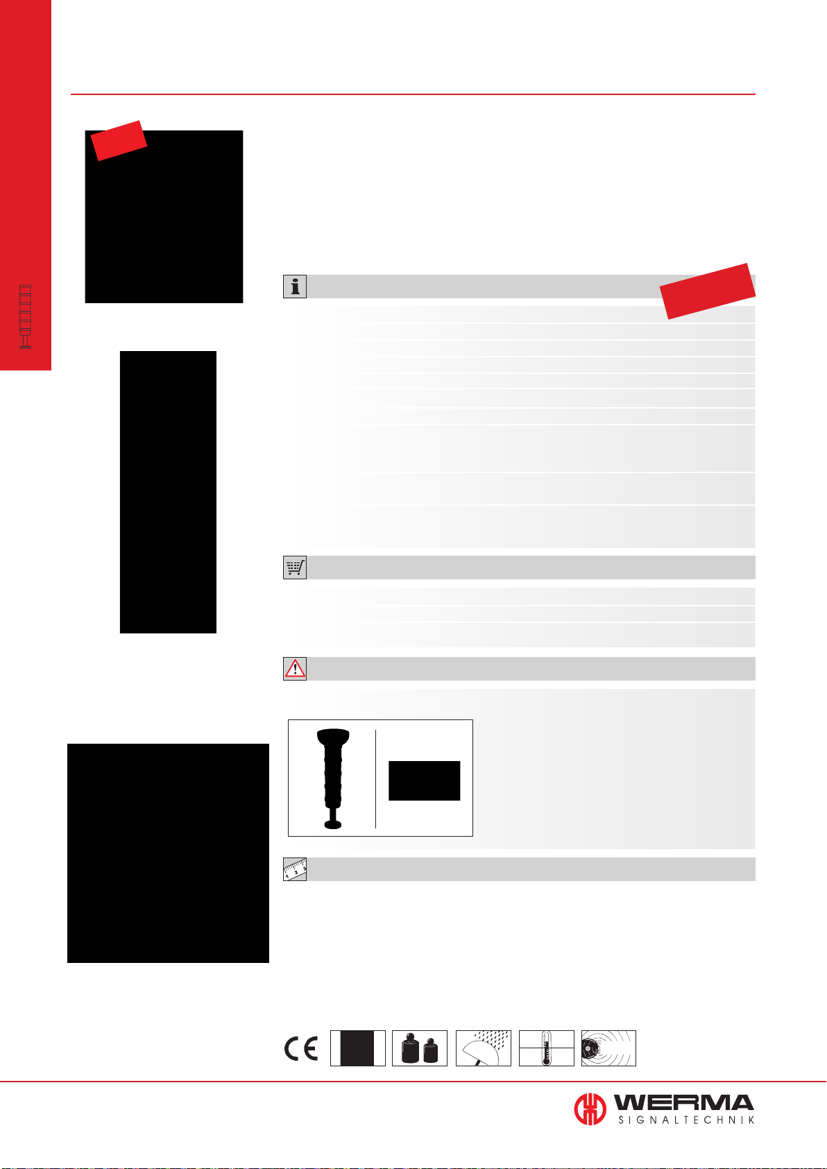
844 Vocal Element for KombiSIGN 70
modular
•
KombiSIGN 70
Signal Towers
NEW
• 102 dB high output vocal element
with excellent tone and sound quality
• Plays customer-specific audio
files (signal tones, music and
• Sound output level can be
triggered externally
• Creation of individual playlists
and playback modes possible
spoken text)
• Easy transfer of audio files and
simple operation
TECHNICAL SPECIFICATIONS:
Dimensions (Ø x Height): 125 mm x 118 mm
Housing: PC/ABS Blend
Lens: PC
Number of signal elements: Max. 4 additional signal elements possible
Sound output: Adjustable, up to 102 dB
File Transfer: Via USB connection and provided software
Possible data format: Mp3 and wav files
Number of sequences: 15 files can be remotely triggered depending
on the number of signal elements used or one
sequence with max. 50 files.
Suitable for: Windows 2000 service pack 4, Windows XP,
Windows Vista, Windows 7, Windows 8
Assembly: Vocal element, USB connection cable
and software
Life duration
up to 5,000 hrs
The vocal element can
be combined with up to
4 signal elements
ORDER SPECIFICATIONS:
Voltage 24 V DC
Current consumption ≤ 400 mA
Vocal element 844 860 55
ADDITIONAL INFORMATION:
Further installation examples:
To ensure IP protection it is recommended
that the vocal element is fitted with the
sound outlet facing downwards.
Optimum distribution of sound is thus
ensured.
TECHNICAL DIAGRAMS:
see page 320
User-friendly software ensures
easy transfer of audio files
and simple operation
56
www.werma.com
See note
on page 347
630 g
IP 54
+50°C
102 dB
-20°C
Page 58
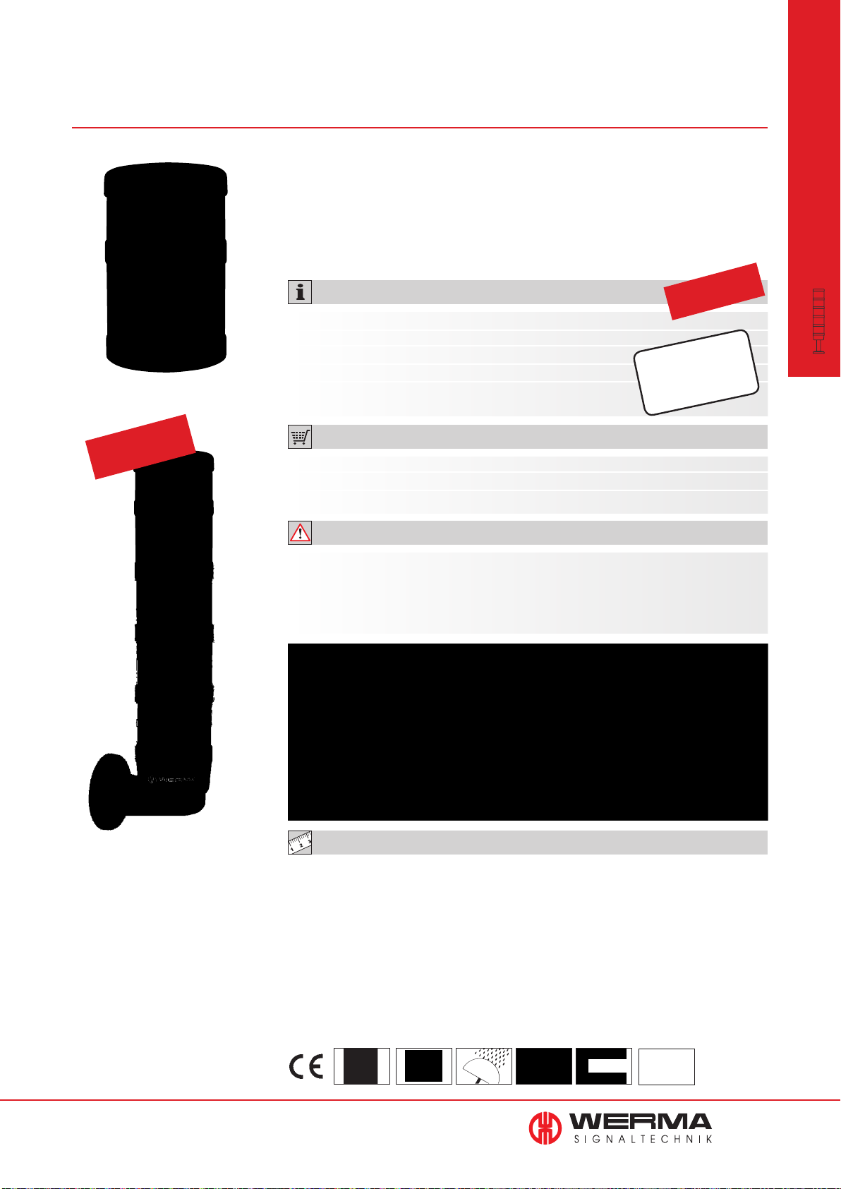
844
Siren Element with self-adjusting
sound output for KombiSIGN 70
Patent
approved
Automatic sound output adjust-
•
ment between 80 and 100 dB
• Sound output is c. 5 dB louder
than the background noise level
TECHNICAL SPECIFICATIONS:
Dimensions (Ø x Height): 70 mm x 110 mm
Housing: PC
Tone type: Pulse tone
Tone frequency: 2.5 KHz
Sound output: 80 dB - max. 100 dB
• Continual measurement of the
ambient noise level
• Ideal for applications with
changing ambient sound levels
Life duration
up to 5,000 hrs
Loud enough
yet
not disturbing!
ORDER SPECIFICATIONS:
Voltage: 24 V DC
Current consumption: < 150 mA
844 810 55
ADDITIONAL INFORMATION:
The siren element adjusts its sound output through continual measurement of the
ambient noise level. The emitted tone is c. 5 dB louder than the background noise level.
The warning signal can always be heard without being irritatingly loud for
people in the sounder’s vicinity.
modular
•
KombiSIGN 70
Signal Towers
www.werma.com
TECHNICAL DIAGRAMS:
see page 319
See note
on page 347
125 g
IP 54
+50°C
-20°C
max100 dB
PLC
57
Page 59
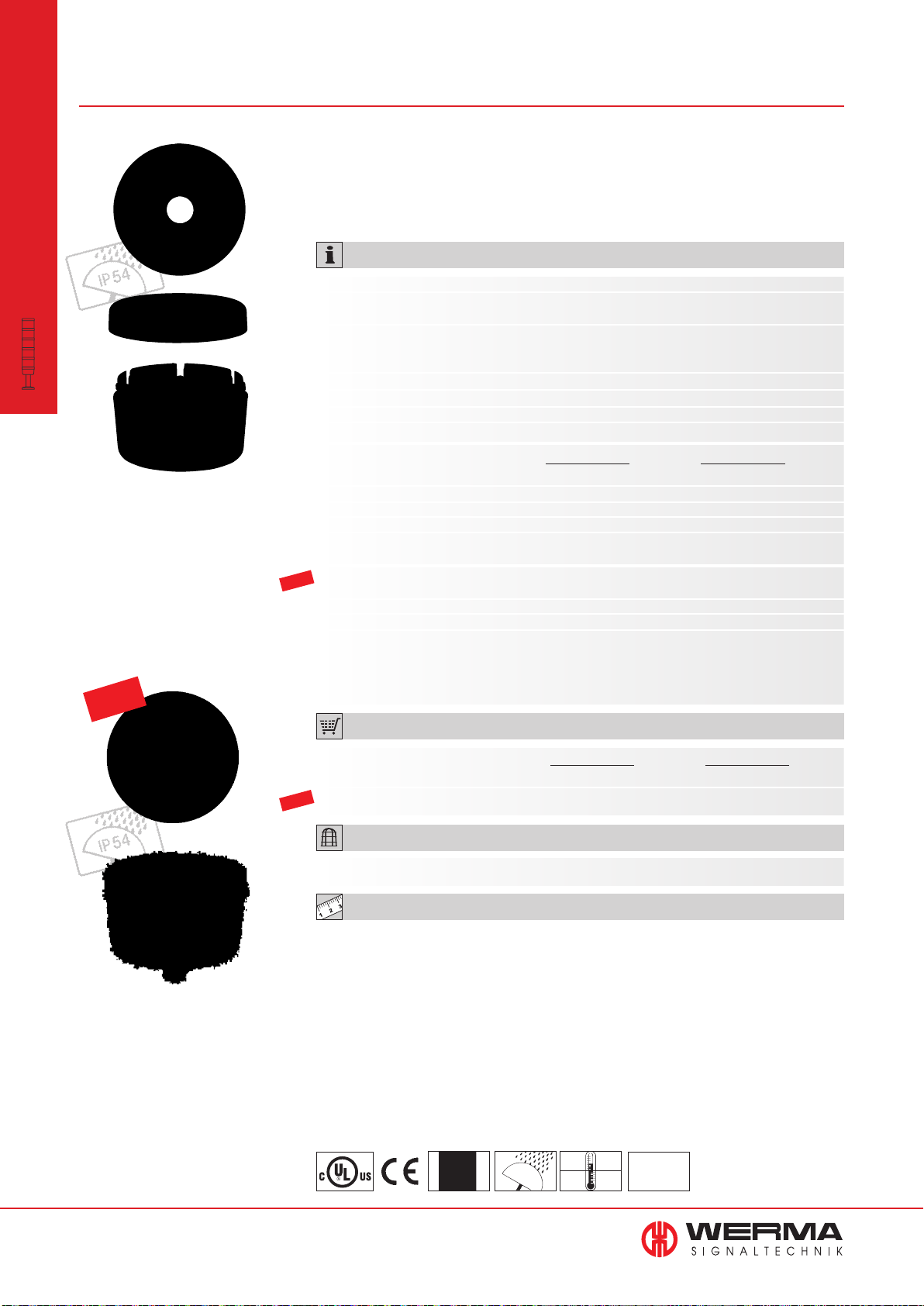
840
Terminal Elements for KombiSIGN 70
modular
•
KombiSIGN 70
Signal Towers
Terminal element with cap
• Bayonet locking mechanism
enables quick and easy assembly
• The ideal solution for every
installation
of the signal tower
TECHNICAL SPECIFICATIONS:
Dimensions (Ø x Height): See below
Lens:
Cap: PC
Fixing: Base mounting
Tube mounting, for tube Ø 25 mm
Bracket mounting (accessory)
Cable entry: Cable diameter max. 14 mm
Element seal: Pre-mounted with each module
Protection rating: IP 54 (with cap)
Number of modules possible: Max. 5
Tube mounting Base mounting
Screw terminal
Dimensions (Ø x Height): 70 mm x 42,5 mm 70 mm x 42,5 mm
Connection: Screw terminal max. 2.5 mm²
Voltage: 12-240 V AC/DC 12-240 V AC/DC
Incl. cap Incl. cap and seal
Terminal element M12
NEW
Dimensions (Ø x Height): 70 mm x 56 mm 70 mm x 50 mm
Connection: M12 connector (8 pole) M12 connector (8 pole)
Voltage: 12-24 V DC 12-24 V DC
Current carrying capacity: ≤ 2 A ≤ 2 A
Incl. cap Incl. cap and seal
No UL approval No UL approval
Terminal element: PA-GF, high-impact
NEW
Terminal element with practical
M12 connection socket in base
ORDER SPECIFICATIONS TERMINAL ELEMENTS:
Tube mounting Base mounting
Screw terminal 840 080 00 840 085 00
Terminal element M12 840 860 55 840 850 55
NEW
ACCESSORIES:
Suitable accessories can be found on page 67.
TECHNICAL DIAGRAMS:
see page 318
See note
840 08X 00
on page 347
IP 54
+50°C
-20°C
PLC
58
www.werma.com
Page 60
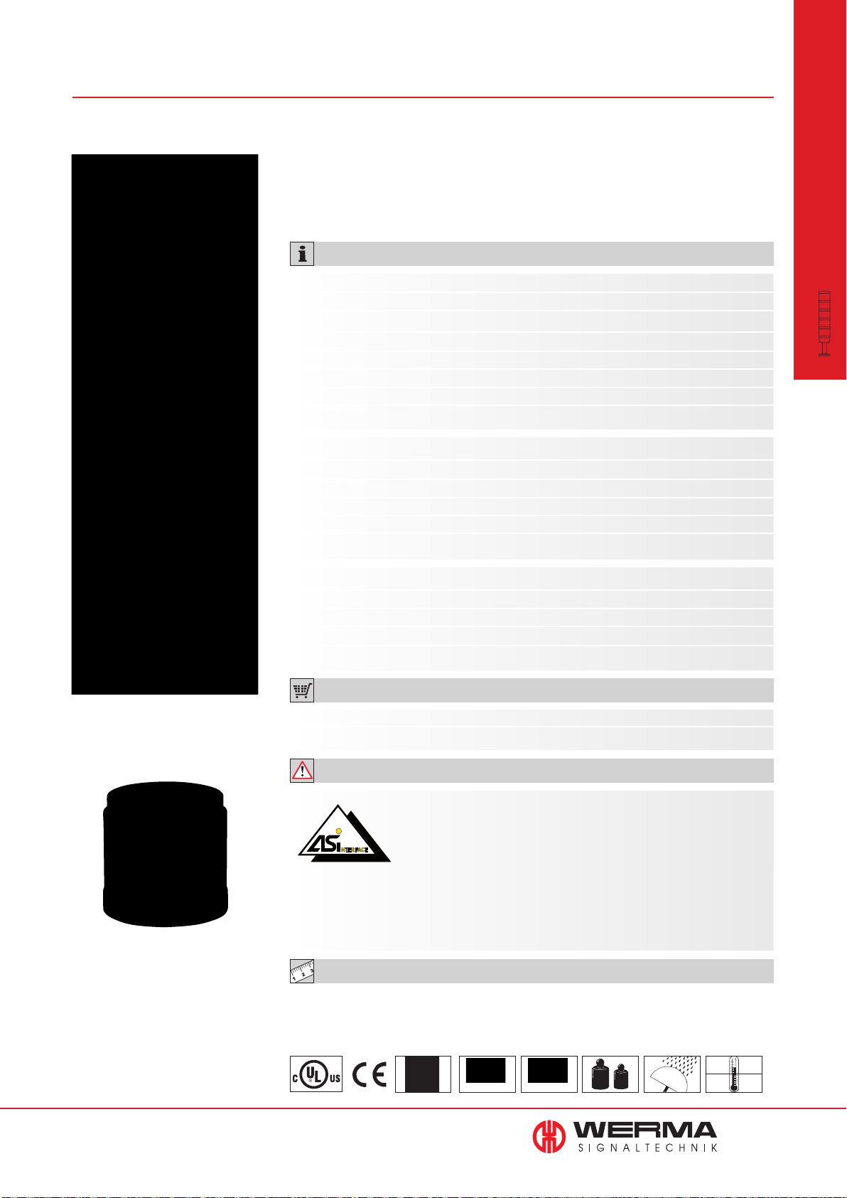
840 AS-Interface Element for KombiSIGN 70
• LEDs indicate current status
• 31 or 62 addresses
• Available with standard or
A/B technology
• Voltage supply switchable from
internal bus supply to additional
external voltage supply
• With addressing socket
TECHNICAL SPECIFICATIONS:
Standard Slave A/B-Slave
Number of addresses: Max. 31 Max. 62
Number of signal elements: Max. 4 Max. 3
IO-Code: 8
ID-Code: F
ID2-Code: N/A E
Outputs: 4 semiconductor relays 3 semiconductor relays
Approved in accordance with: Spec. V 3.0 Spec. V 3.0
Specif. Power supply
AS-Interface Element: Via bus conduction
Operating voltage: 18.5 V … 31.6 V according to the AS-Interface specification
Reverse battery protection: Integrated
Watchdog: Integrated
Additional external voltage: 24 V DC
8
Hex
A
Hex
Hex
Hex
Hex
modular
•
KombiSIGN 70
Signal Towers
Cable not included in assembly
LEDs display the
current status
With internal add. voltage With external add. voltage
Current carrying cap. Σ Imax: 200 mA 200 mA per signal element
Current consumption max: 210 mA 50 mA
Voltage at signal element: 20 V ... 30 V DC 24 V +/- 10%
Short circuit/overload protect
ion: Integrated Pre-fuse M 1.6 A
ORDER SPECIFICATIONS:
AS-Interface Element Standard Slave A/B-Slave
840 830 55 840 810 55
ADDITIONAL INFORMATION:
The KombiSIGN Signal Tower 70 with AS-Interface Element are
capable of total communication: Through simple integration of an
AS-Interface Element the actuators are connected to the networking system Actuator-Sensor-Interface - this con-siderably reduces
complex wiring.
The necessary power supply (supply via bus or external) can be selected with a switch.
This element is mounted as the first tier of the individual signal tower directly on top of
the terminal element. (Further Information see page 351).
TECHNICAL DIAGRAMS:
see page 318
www.werma.com
Class 2
See note
on page 347
Standard Slave A/B-Slave
Approval No. 66301 Approval No. 66202
77 g
IP 54
+50°C
-20°C
59
Page 61
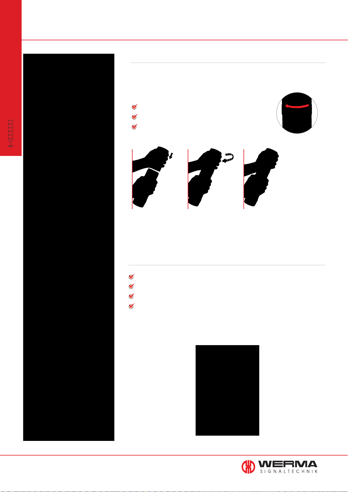
Signal Tower KombiSIGN 50
modular
•
KombiSIGN 50
Signal Towers
Simple operation thanks to bayonet mechanism
WERMA was the first signal beacon manufacturer to
offer a bayonet mechanism allowing elements to be
mechanically and electrically connected within
seconds.
Simple mounting and removal of the elements
New combinations at the twist of a hand
Tool-free bulb change
Signals to combine - At the twist of a hand
Signal elements in every common voltage
Modular system allows combination as required
Protection rating IP 54
LED technology ensures even better visibility
60
www.werma.com
Page 62
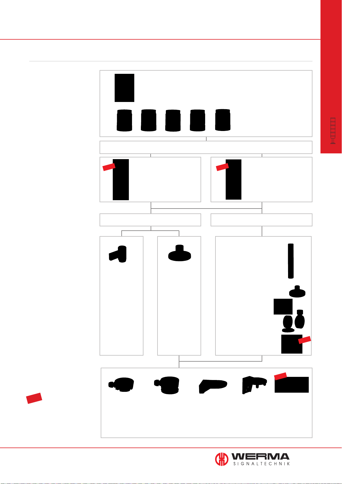
This is how you can assemble your KombiSIGN 50 signal tower
STEP 1
Select the required optical or
audible elements in the correct
voltage.
STEP 2
Select the terminal element.
NEW
Terminal element
NEW
Audible Signal Elements
• Buzzer element
Optical Signal Elements
• Permanent light
• LED Permanent light
• LED Flashing light
• LED Blinking light
Single hole Mounting
Terminal element with
CAGE CLAMP
single hole mounting
®
technology for
modular
•
KombiSIGN 50
Signal Towers
STEP 3
Select the appropriate mounting
option for your application.
STEP 4
Select the appropriate accessory
for your mounting option.
Bracket for
wall mounting
Order no.
975 845 02
Order no.
845 000 00
Base/Wall Mounting
Base for surface
mounting,
incl. rubber seal
Order no.
975 845 01
Order no.
845 010 00
Tube Mounting
Tube Ø 25 mm, Aluminium
Order no.
100 mm long 975 845 10
250 mm long 975 840 25
400 mm long 975 840 40
600 mm long 975 840 60
800 mm long 975 840 80
1000 mm long 975 840 03
Base for tube, plastic
Order no. 975 840 90
Base for tube, metal
Order no. 975 840 91
Foldaway base
Order no. 960 000 30
Foldaway base
Order no. 960 009 12
NEW
STEP 5
Where appropriate, select the
bracket and the contact box.
TIP
The Signal Devices Site on the
Internet: www.werma.com
With our new signal tower configu-
rator you can put together your own
individual signal tower.
www.werma.com
Contact box for cable
exit at side
Order no.
975 840 01
Contact box with
magnetic base and
cable exit at side
Order no.
975 840 04
Bracket for base mounting
with concealed cable entry
Order no.
960 000 14
Bracket for
base mounting
Order no.
960 000 01
NEW
Corner fixing
bracket
Order no.
960 000 41
61
Page 63
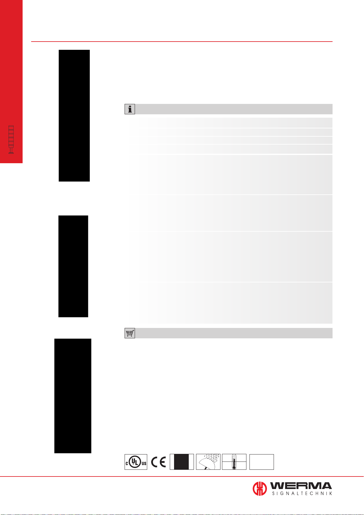
Optical Signal Elements KombiSIGN 50846/848
modular
•
KombiSIGN 50
Signal Towers
Tube mounting (accessory)
• Clear signalling, even in
unfavourable light conditions
• LED light elements have an
extremely long life and low
current consumption
TECHNICAL SPECIFICATIONS:
Dimensions (Ø x Height): 52 mm x 67 mm
Lens: PC, transparent
Protection rating: IP 54
Number of modules possible: Max. 4
Permanent light element 12-240 V AC/DC
Bulb not included in assembly
Socket: Bayonet, BA15d, for bulb max. 5 W
Life duration: Dependent upon the bulbs used
LED Permanent light element 24 V AC/DC 115 V AC 230 V AC
Current consumption: 45 mA 25 mA 25 mA
Life duration: < 50,000 hrs
Bracket (accessory)
LED Flashing light element
Current consumption: Red, yellow Green, clear, blue
45 mA 40 mA
Life duration: < 50,000 hrs
Blink frequency: C. 1 Hz
LED Blinking light element 24 V AC/DC 115 V AC 230 V AC
Current consumption: 25 mA 25 mA 25 mA
Life duration: < 50,000 hrs
Blink frequency: C. 1 Hz
ORDER SPECIFICATIONS OPTICAL ELEMENTS:
see next page
Base mounting (accessory)
62
www.werma.com
See note
on page 347
IP 54
+50°C
-20°C
24 V
PLC
Page 64
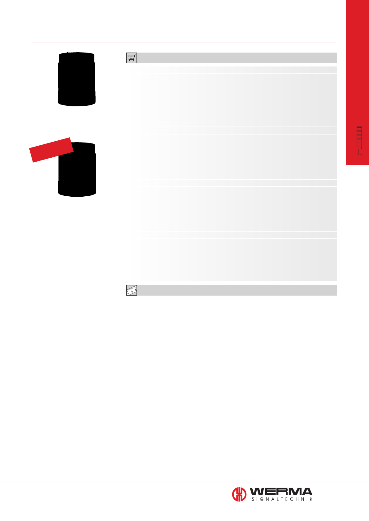
ORDER SPECIFICATIONS OPTICAL ELEMENTS:
Permanent light element
Life duration
up to 50,000 hrs
LED element
Permanent light element 12-240 V AC/DC
red 846 100 00
green 846 200 00
yellow 846 300 00
clear 846 400 00
blue 846 500 00
Bulb not included in assembly. Accessories see page 67.
LED Permanent light element 24 V AC/DC 115 V AC 230 V AC
red 848 100 55 848 100 67 848 100 68
green 848 200 55 848 200 67 848 200 68
yellow 848 300 55 848 300 67 848 300 68
clear 848 400 55 848 400 67 848 400 68
blue 848 500 55 848 500 67 848 500 68
LED Flashing light element 24 V DC
red 848 120 55
green 848 220 55
yellow 848 320 55
clear 848 420 55
Life duration
up to 50,000 hrs
blue 848 520 55
LED Blinking light element 24 V AC/DC 115 V AC 230 V AC
red 848 110 75 848 110 67 848 110 68
green 848 210 75 848 210 67 848 210 68
yellow 848 310 75 848 310 67 848 310 68
clear 848 410 75 848 410 67 848 410 68
blue 848 510 75 848 510 67 848 510 68
modular
•
KombiSIGN 50
Signal Towers
TECHNICAL DIAGRAMS:
see page 320 onwards
www.werma.com
63
Page 65
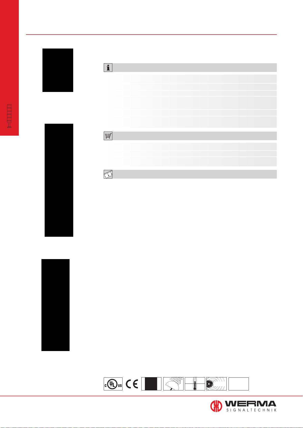
modular
•
KombiSIGN 50
Signal Towers
Buzzer element
Audible Elements for KombiSIGN 50849
• Optional continuous or pulse tone• Buzzer with up to 80 dB
TECHNICAL SPECIFICATIONS:
Dimensions (Ø x Height): 52 mm x 72 mm
Lens: PC/ABS-Blend
Protection rating: IP 54
Number of modules
possible: Max. 4
Sound output: 80 dB
Number/Tone type:
ORDER SPECIFICATIONS AUDIBLE ELEMENT:
Continuous or pulse tone, adjustable
Tube mounting (accessory)
Voltage 24 V AC/DC
115 V AC/DC
230 V AC
Current consumption Max. 25 mA Max. 25 mA Max. 25 mA
Buzzer element 849 000 75 849 000 77 849 000 68
TECHNICAL DIAGRAMS:
see page 320 onwards
Base mounting (accessory)
64
www.werma.com
See note
on page 347
IP 54
+50°C
-20°C
80 dB
24 V
PLC
Page 66
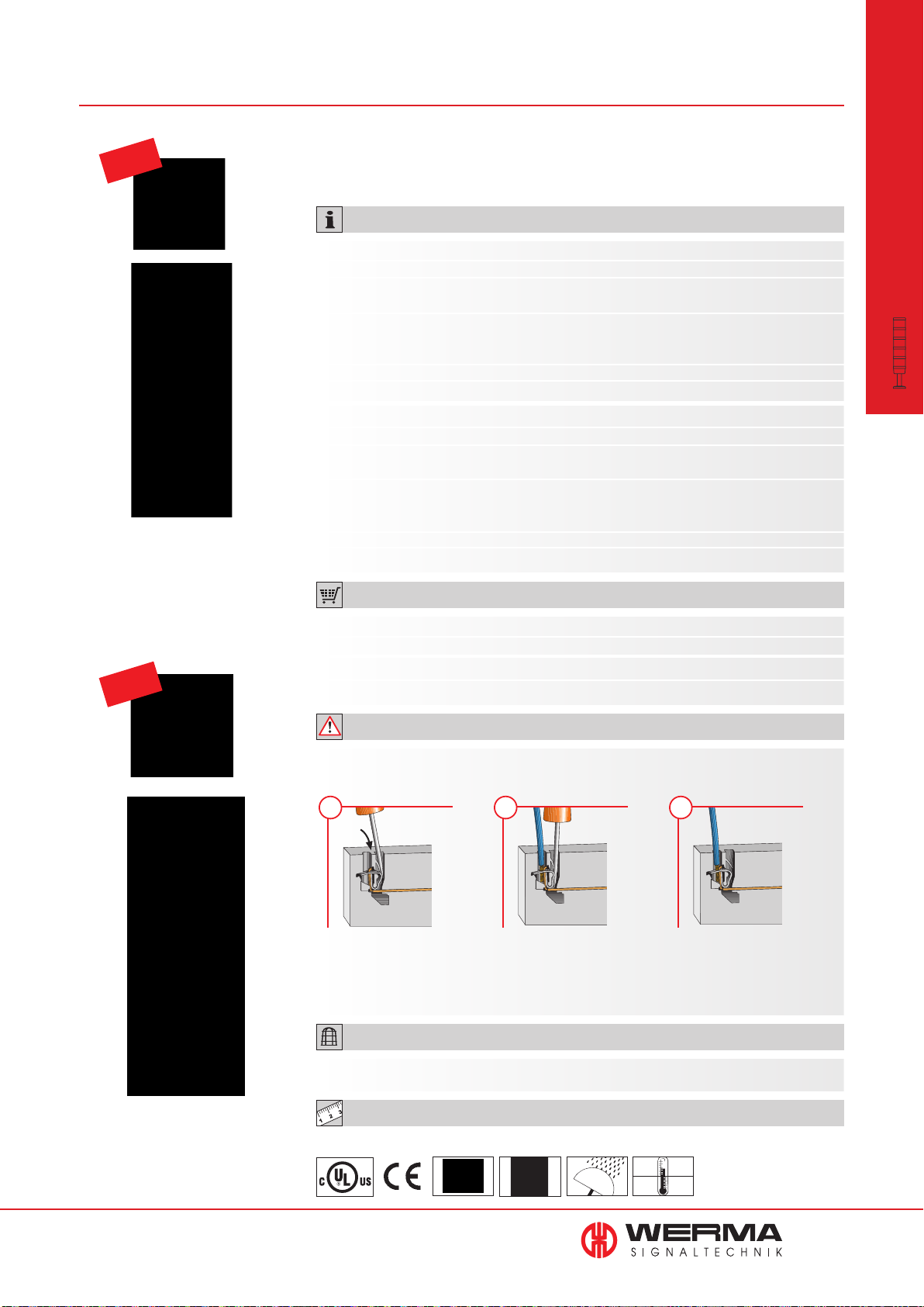
Terminal Elements for KombiSIGN 50845
NEW
Screw terminal with cap
• Bayonet locking mechanism
enables quick and easy assembly
• The ideal solution for every
installation
of the signal tower
TECHNICAL SPECIFICATIONS:
Terminal element
Dimensions (Ø x Height): 52 mm x 65 mm
Material: Terminal element: PA + PC/ABS
Cap: PC
Fixing: Tube mounting, for tube Ø 25 mm
Single hole mounting, Base and bracket
mounting (accessory)
Connection: Screw terminal max. 1.5 mm
Cable entry: Cable diameter max. 9.5 mm
Terminal element with CAGE CLAMP
®
technology
Dimensions (Ø x Height): 52 mm x 65 mm
Material: Terminal element: PA + PC/ABS
Cap: PC
Fixing: Tube mounting, for tube Ø 25 mm
Base mounting, Single hole mounting and bracket
mounting (accessory)
Connection: CAGE CLAMP
®
technology max. 1.5 mm
Cable entry: Cable diameter max. 9.5 mm
2
2
modular
•
KombiSIGN 50
Signal Towers
NEW
ORDER SPECIFICATIONS TERMINAL ELEMENTS:
Terminal element 845 000 00
incl. cap, rubber seal and nut
®
Terminal element with CAGE CLAMP
845 010 00
incl. cap, rubber seal and nut
ADDITIONAL INFORMATION:
Terminal elements with CAGE CLAMP® technology enable leads to be quickly and easily wired,
guaranteeing a secure and reliable contact.
1 2 3
Insert screwdriver at a slight
angle into opening as far
as possible.
CAGE CLAMP® is a registered trademark of WAGO Kontakttechnik GmbH.
Open spring-loaded clamp with
the help of the screwdriver and
insert wire as far as possible.
Remove screwdriver the wire is firmly
clamped.
ACCESSORIES:
Terminal element CAGE CLAMP®
Technologie with cap
www.werma.com
Suitable accessories can be found on page 67.
TECHNICAL DIAGRAMS:
125 g
see page 320
See note
on page 347
IP 54
+50°C
-20°C
65
Page 67
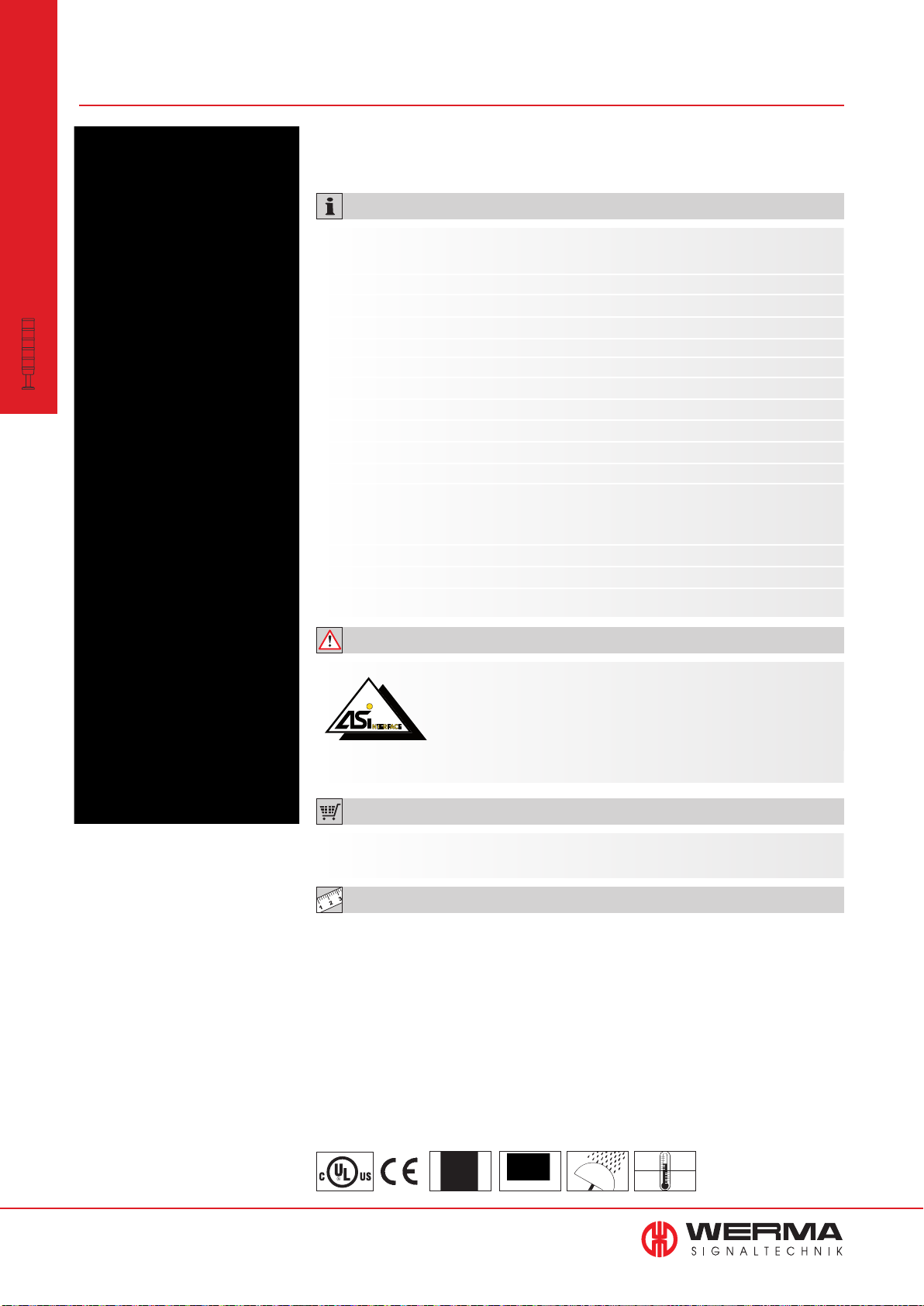
modular
•
KombiSIGN 50
Signal Towers
AS-Interface Element for KombiSIGN 50845
• Available with standard
technology for 31 adresses
TECHNICAL SPECIFICATIONS:
AS-Interface Element with additional
external voltage
Number of adresses: Max. 32
Number of signal elements: Max. 4
IO-Code: 8
ID-Code: F
ID2-Code: N/A
Power supply: Via bus conduction
Operating voltage: 18.5 V … 31.6 V
Current consumption Imax: 50 mA
Polarity reversal protection: Integrated
Watchdog: Integrated
Outputs: 4, relays
On-load voltage: Additional external voltage:
10 V…30 V DC
10 V…230 V AC
Current carrying cap. Σ Imax: 1.5 A
Short circuit/overload pro.: Fuse M 1.6 A
Hex
Hex
Cable not included in assembly
ADDITIONAL INFORMATION:
The KombiSIGN 50 Signal Tower with AS-Interface Element is capable
of total communication: Through simple integration of an AS-Interface
Element the actuators are connected to the networking system ActuatorSensor-Interface - this considerably reduces complex wiring.
This element is mounted as the first tier of the individual signal tower
directly on top of the terminal element. (Further Information see page 351).
ORDER SPECIFICATIONS:
AS-Interface-Element 845 800 68
with add. external voltage
TECHNICAL DIAGRAMS:
see page 320
66
www.werma.com
See note
on page 347
Approval No.
2001
IP 54
+50°C
-20°C
Page 68
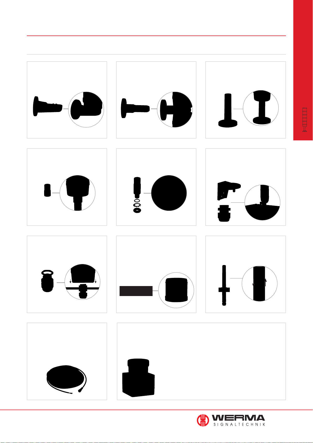
Overview Accessories for KombiSIGN
KombiSIGN 70 and 71
Bracket for 1-sided mounting,
incl. rubber seals
Order no. 975 840 85
Bracket for 2-sided mounting,
incl. rubber seals
Order no. 975 840 86
Base with integrated tube,
Ø 25 mm, 110 mm long,
plastic, incl. rubber seal
Order no. 975 840 10
modular
•
Accessories KombiSIGN 50, 70 and 71
Signal Towers
Adaptor for tube mounting
Ø 25 mm / 1/2” NPT thread
Order no. 975 840 02
Cable gland for surface
mounting, M16 x 1.5
Order no. 960 000 04
Adaptor for single hole mounting
Ø 25 mm, M18
Order no. 960 000 25
Info transparencies
Order no.
Number "0" - "9"
Number "10"
Neutral
Arrow
975 840 50 - 59
975 840 92
975 840 49
975 840 62
Bracket for surface mounting
incl. cable gland
M16 x 1.5
Order no. 960 000 02
Tube with clamp, Ø 25 mm,
250 mm long, incl. cable gland
Order no. 960 000 18
Cable 5 m with M12 connector and plug
Order no. 960 000 46
Cable 5 m with M12 plug
Order no. 960 000 47
Cable 5 m with M12 connector
Order no. 960 860 01
www.werma.com
Interface box and terminal element for KombiSIGN 71
(only for the permanent light element 641 X00 00 and corresponding light bulb (24V))
Interface box and terminal element
with 2 cable glands M16
Order no. 960 000 16
Drive: 24 V DC
Interfaces: RS 232, RS 485
Assembly: Network appliance with cable, connecting
cable RS 232, 2 m long with Sub-D 9-pin
and socket for power supply, CD with
demonstration programme, programming
handbook
Interface box and terminal element
with 1 cable glands M16 and assembly
Order no. 960 000 17
67
Page 69
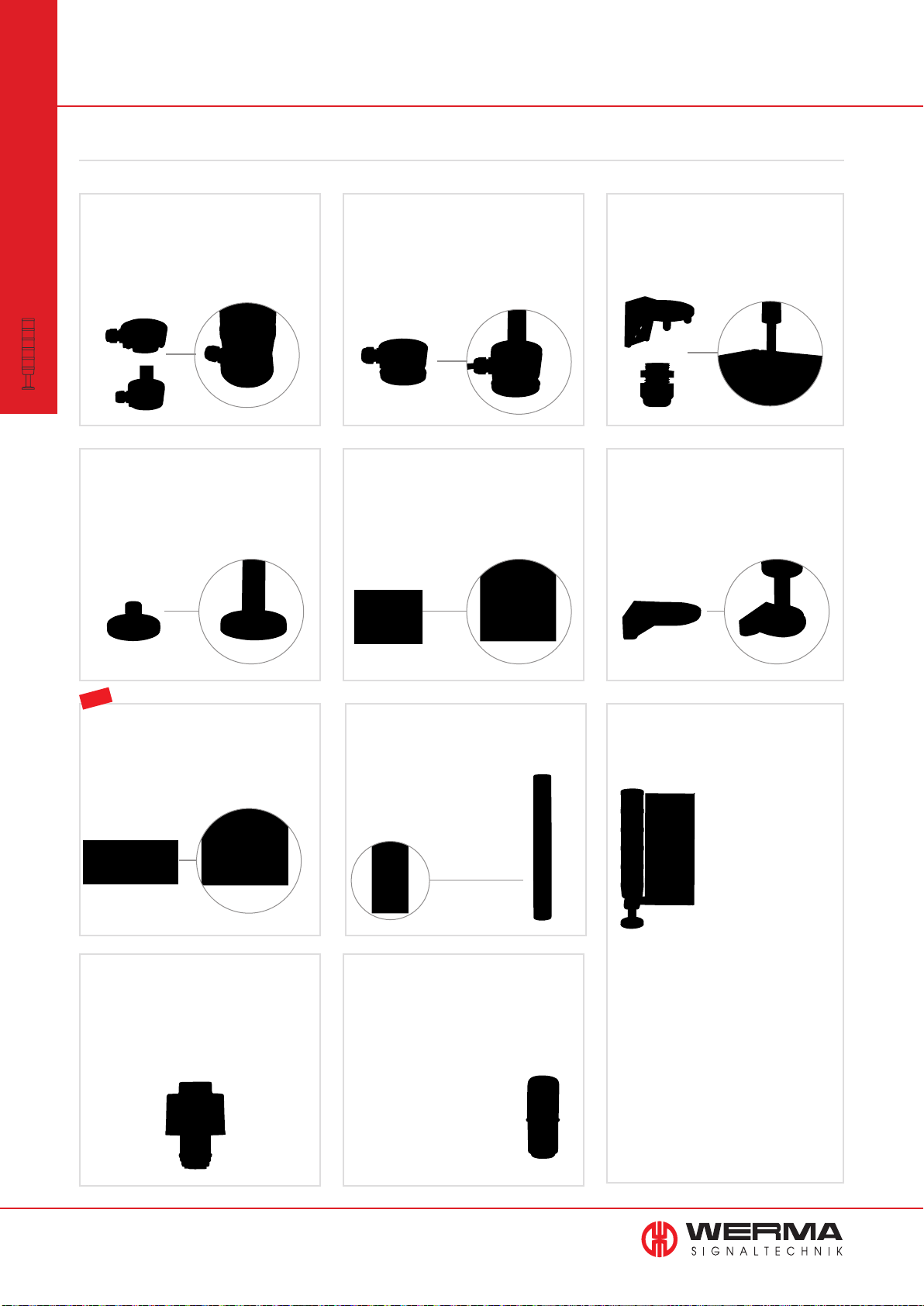
Overview Accessories KombiSIGN
KombiSIGN 50, 70 and 71
modular
•
Contact box for cable exit
at side, with mounting material
and seal, cable gland M16 x 1.5
Order no. 975 840 01
Accessories KombiSIGN 50, 70 and 71
Signal Towers
Contact box with magnetic
base and cable exit at side
cable gland M16 x 1.5
Order no. 975 840 04
Bracket for tube mounting,
incl. cable gland M16 x 1.5
Order no. 960 000 01
Base for tube mounting, Ø 25 mm,
plastic, incl. rubber seal
Order no. 975 840 90
NEW
Corner fixing bracket
Order no. 960 000 41
Base for tube Ø 25 mm, metal,
incl. rubber seal, recommended for tube
lengths of 400 mm and longer
Order no. 975 840 91
Tube Ø 25 mm, all anodized aluminium
100 mm long 975 845 10
250 mm long 975 840 25
400 mm long 975 840 40
600 mm long 975 840 60
800 mm long 975 840 80
1000 mm long 975 840 03
Bracket for base mounting,
with concealed cable entry,
incl. rubber seals
Order no. 960 000 14
Indication board
(for tube mounting)
Order no. 960 000 05
• For one to five
Fault
modules
Refill
Overheating
Station 2
Machine in
operation
• Simple mounting
onto signal tower
tube
• Ample space for
written information
• Simply break off
unwanted segments
LED bulb BA15d
total length max. 42 mm
Colours: red, yellow, green, clear, blue
Voltage 24 V, 115 V, 230 V
Order specifications see page 185
68
www.werma.com
Bulb BA15d,
total length max. 42 mm
12 V, 5 Watt 955 840 34
24 V, 5 Watt 955 840 35
30 V, 5 Watt 955 840 32
115 V, 5 Watt 955 840 57
230 V, 5 Watt 955 840 38
Dimensions of indication board (W x H):
153 x 345 mm
Surface area per section (W x H):
c. 144 x 54 mm, e.g.
Zweckform 3424 (105 x 48 mm),
Herma 4281 (105 x 50.8 mm)
(not included in assembly)
Material: PMMA
Page 70
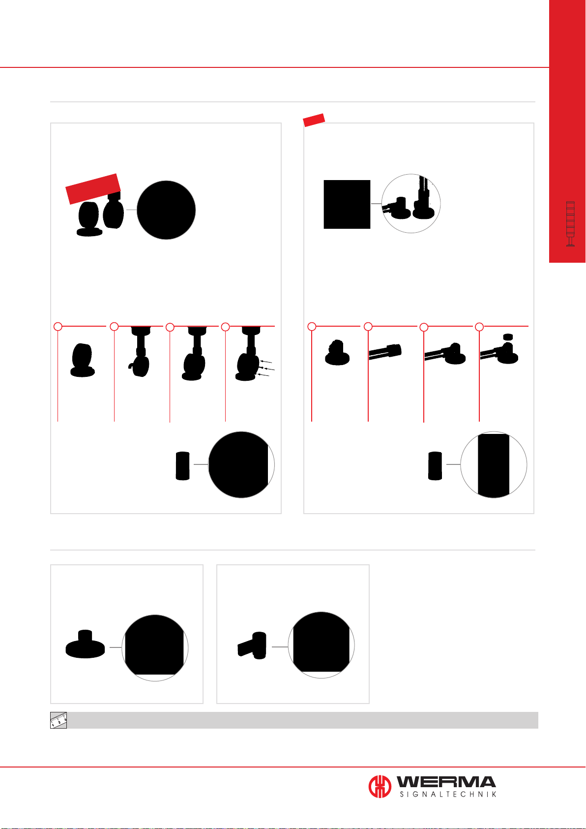
KombiSIGN 50, 70 and 71
Foldaway Base - Signal Tower can be folded away, including
rubber seal, for tube (all anodized aluminium) Ø 25 mm
(not included in assembly)
Order no. 960 000 30
Utility model
approved
NEW
Foldaway Base - Signal Tower can be folded away, including
rubber seal, for tube (all anodized aluminium) Ø 25 mm
(not included in assembly)
Order no. 960 009 12
modular
•
Accessories KombiSIGN 50, 70 and 71
Signal Towers
Dimensions (Ø x Height): 70 mm x 117 mm
Material: PA-GF
Cable diameter: Max. 14 mm
Fixing: Vertical, horizontal,
Positioning in 7,5° steps
QUICK AND SIMPLE MOUNTING:
1 1
Place the lower part
of the Foldaway
Base in the desired
position
2 2
Attach the upper
part directly onto the
signal tower tube.
Insert the connection
cable
Place the upper
and lower parts
together at the
desire angle
4 4
Place the upper and
lower parts together
at the desired angle
Tube Ø 25 mm, plastic,
45 mm long, for direct mounting
of the Terminal Element onto the
Foldaway Base
(only for KombiSIGN 70 and 71)
Order no. 960 000 31
Dimensions (Ø x Height): 70 mm x 85 mm
Material: PA-GF
Cable diameter: Max. 8 mm
Fixing: Vertical, horizontal,
Positioning in 0° and 90°
QUICK AND SIMPLE MOUNTING:
33
Place the „foldaway“
base in the desired
mounting position
Attach the tube
adaptor directly to
the signal tower and
introduce the cable
Fix the whole assembly - tube adaptor
and signal tower, in
the desired position,
vertically or horizontally - onto the
foldaway base
Tube Ø 25 mm, plastic,
45 mm long, for direct mounting
of the Terminal Element onto the
Foldaway Base
(only for KombiSIGN 70 and 71)
Order no. 960 000 31
Place the cover on
the other open end
KombiSIGN 50
Base for surface mounting,
incl. rubber seal
Order no. 975 845 01
TECHNICAL DIAGRAMS:
see page 327 onwards
www.werma.com
Bracket for wall mounting
Order no. 975 845 02
69
Page 71

KOMPAKT
•
completely
•
pre-assembled
Signal Towers
Page 72
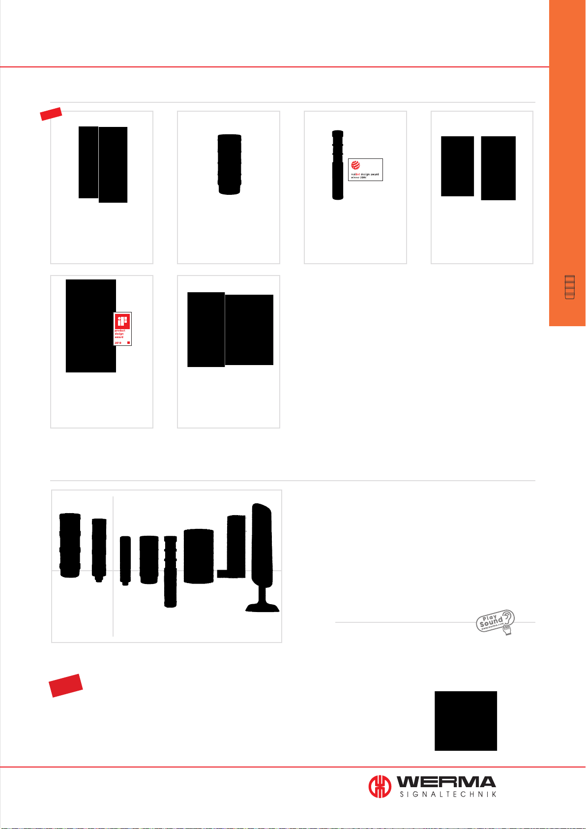
Overview Signal Towers • pre-assembled
Pre-assembled Signal Towers
NEW
698/699 KOMPAKT 37
• Ø 37.5 mm
• Protection rating IP 65
• 2-5 tiers
• With or without buzzer
Page 73
690 VarioSIGN
• 62 x 220 x 90 mm
• Protection rating IP 65
• Electronic modularity
• Unique Design
697 KOMPAKT 71
• Ø 70 mm
• Protection rating IP 65
• 2 or 3 tiers
Page 77
695 CleanSIGN
• IP 67/69 k
• For base and bracket
mounting
694 deSIGN 42
• Ø 42 mm
• Protection rating IP 65
• 2 or 3 tiers
• High quality stainless
steel housing
Page 82
691 FlatSIGN
• 195 x 105 x 45 mm
• Protection rating IP 65
• With curved front
• 160° signal visibility
Page 84
completely
•
pre-assembled
Signal Towers
Page 86
Page 90
Size comparison · Signal Towers
modular pre-assembled
KombiSIGN
KombiSIGN 50KOMPAKT37KOMPAKT71deSIGN42FlatSIGN VarioSIGN CleanSIGN
70/71
TIP
The Signal Devices Site on the internet: www.werma.com
On the signal tower pages of www.werma.com use the selection tool „Configurator“ to select the Kompakt 37
signal tower according to your requirements. With the help of intuitive questions and pictures you will be able to
make your choice with just a few mouse clicks.
Sound
The sounds can be played from our website
www.werma.com under the heading "Signal Towers"
www.werma.com
71
Page 73
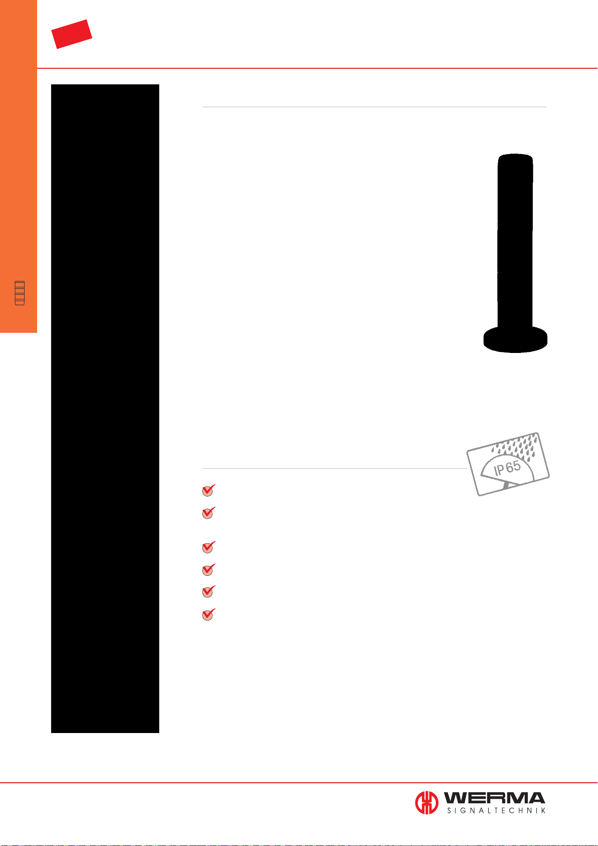
NEW
KOMPAKT 37
•
completely
•
pre-assembled
Signal Towers
KOMPAKT 37
The complete Signal Tower Solution
The slim-line LED signal tower is available with black housing and
coloured lens or in a metallic colour with clear lens.
In the version with coloured lens, the the LEDs light up within the
tower in the colour of the lens giving an intensive colour effect whilst
the clear lens give clear colour signal even in bright sunlight.
The clear lenses ensure an unequivocal signal even in bright light
conditions thus ruling out errors even in bad light conditions.
The aesthetically pleasing and innovative plastic housing with metallic coating also makes the signal towers an excellent choice in areas
where the optical effect is of importance.
Additional warning can be given with the optional siren built into the
top of the signal tower. With an output of 85 dB the siren gives an
immediate and clear warning of potential danger, and the tower
carries a protection rating of IP 65.
The advantages at a glance
Completely pre-assembled LED Signal Tower
Simplifi ed ordering - the complete tower can be ordered
with just one number
Life duration of up to 50,000 hours
High protection rating IP 65
Up to 5 optical and one audible element
Available with M12 plug or cable connection
72
www.werma.com
Page 74
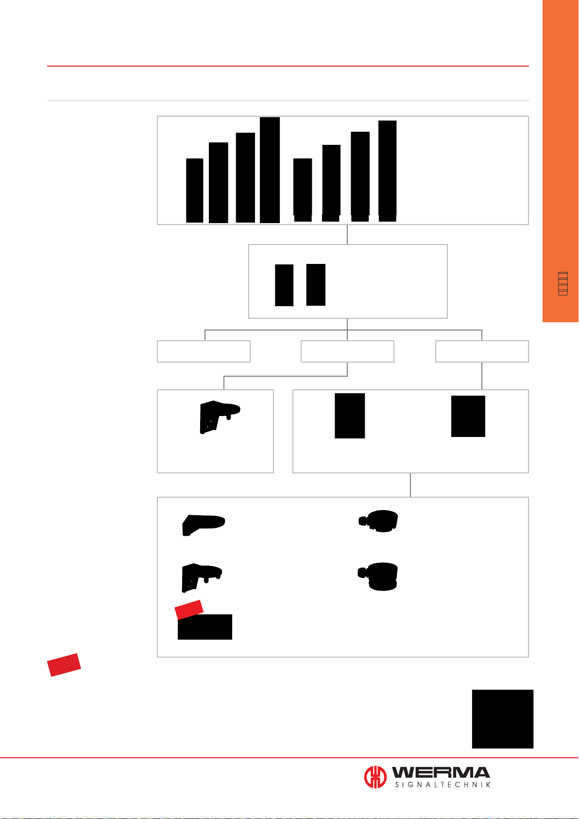
698/699 LED Signal Tower KOMPAKT 37
This is how to select your signal tower
STEP 1
Select the signal tower of your
choice with or without buzzer, with
the appropriate connection,
housing colour, voltage and
number of tiers.
Part numbers can be found on
pages 74 and 75.
STEP 2
Select up to two extension tubes.
optional:
Extension tube, black
Order no. 960 698 02
Extension tube, silver finish
Order no. 960 698 04
• 2-5 tiers
• With or without buzzer
• M12 plug or cable
• Black or silver finish
KOMPAKT 37
•
completely
•
pre-assembled
Signal Towers
STEP 3
Select the appropriate fixing
accessories for your application,
using for example a tube and
base or a bracket mount.
STEP 4
Where appropriate, select the
bracket and the contact box.
Single Hole Mounting Bracket Mounting Base Mounting
Bracket for base mounting
Order no. 960 698 05
Bracket for base mounting with
concealed cable entry
Order no. 960 000 14
Bracket for tube mounting
Order no. 960 000 01
NEW
Corner fixing bracket
Order no. 960 000 41
Base with integrated tube,
black
Order no.
960 698 01
Base with integrated tube,
silver finish
Order no.
Contact box for cable exit at side
Order no. 975 840 01
Contact box with magnetic base
and cable exit at side
Order no. 975 840 04
960 698 03
TIP
The Signal Devices Site on the internet: www.werma.com
On the signal tower pages of www.werma.com use the selection tool „Configurator“ to select the Kompakt 37 signal
tower according to your requirements. With the help of intuitive questions and pictures you will be able to make your
choice with just a few mouse clicks.
www.werma.com
73
Page 75
698/699 LED Signal Tower KOMPAKT 37
KOMPAKT 37
•
completely
•
pre-assembled
Signal Towers
NEW
Two tier Kompakt 37 with
integral tube and base
(accessory)
• Pre-assembled signal tower with
max. 5 tiers
• With or without buzzer
• LED permanent light
TECHNICAL SPECIFICATIONS:
Dimensions (Ø x Height): 2 tier: 37.5 mm x 127.5 mm
3 tier: 37.5 mm x 161.5 mm
4 tier: 37.5 mm x 195.5 mm
5 tier: 37.5 mm x 229.5 mm
(Protrusion from panel)
Housing: PC
Fixing: Single hole mounting for Ø 22.5 mm (M22 x 1.5 mm)
Base or bracket mounting (accessory)
Connection: Cable connection: Cable, 2 m long,
Plug connection: M12 Plug (2/3 tier: 5 pole;
4/5 tier: 8 pole)
Current consumption: 50 mA per tier / buzzer 24 V
125 mA per tier / buzzer 12 V
Nut and seal included in assembly.
• Available with M12 plug or cable
connection
• Also available in metal finish and
clear lens
Life duration
up to 50,000 hrs
ORDER SPECIFICATIONS:
KOMPAKT 37 with coloured lens and buzzer
Connection 24 V AC/DC 12 V AC/DC
2 tier green/red Cable 699 120 75 699 120 74
yellow/red Cable 699 130 75 699 130 74
green/red Plug 699 220 75 699 220 74
yellow/red Plug 699 230 75 699 230 74
3 tier green/yellow/red Cable 699 110 75 699 110 74
green/yellow/red Plug 699 210 75 699 210 74
4 tier clear/green/yellow/red Cable 699 140 75
blue/green/yellow/red Cable 699 150 75
clear/green/yellow/red Plug 699 240 75
blue/green/yellow/red Plug 699 250 75
5 tier blue/clear/green/yellow/red Cable 699 160 75
blue/clear/green/yellow/red Plug 699 260 75
Three tier Kompakt 37
with bracket (accessory)
74
www.werma.com
KOMPAKT 37 with coloured lens and without buzzer
Connection 24 V AC/DC 12 V AC/DC
2 tier green/red Cable 698 120 75 698 120 74
yellow/red Cable 698 130 75 698 130 74
green/red Plug 698 220 75 698 220 74
yellow/red Plug 698 230 75 698 230 74
3 tier green/yellow/red Cable 698 110 75 698 110 74
green/yellow/red Plug 698 210 75 698 210 74
4 tier clear/green/yellow/red Cable 698 140 75
blue/green/yellow/red Cable 698 150 75
clear/green/yellow/red Plug 698 240 75
blue/green/yellow/red Plug 698 250 75
5 tier blue/clear/green/yellow/red Cable 698 160 75
blue/clear/green/yellow/red Plug 698 260 75
Page 76
NEW
ORDER SPECIFICATIONS:
KOMPAKT 37 in silver finish with clear lens and buzzer
Connection 24 V AC/DC 12 V AC/DC
2 tier green/red Cable 699 320 75 699 320 74
yellow/red Cable 699 330 75 699 330 74
green/red Plug 699 420 75 699 420 74
yellow/red Plug 699 430 75 699 430 74
3 tier green/yellow/red Cable 699 310 75 699 310 74
green/yellow/red Plug 699 410 75 699 410 74
4 tier clear/green/yellow/red Cable 699 340 75
blue/green/yellow/red Cable 699 350 75
clear/green/yellow/red Plug 699 440 75
blue/green/yellow/red Plug 699 450 75
5 tier blue/clear/green/yellow/red Cable 699 360 75
blue/clear/green/yellow/red Plug 699 460 75
KOMPAKT 37 in silver finish with clear lens and without buzzer
Connection 24 V AC/DC 12 V AC/DC
2 tier green/red Cable 698 320 75 698 320 74
yellow/red Cable 698 330 75 698 330 74
green/red Plug 698 420 75 698 420 74
yellow/red Plug 698 430 75 698 430 74
3 tier green/yellow/red Cable 698 310 75 698 310 74
green/yellow/red Plug 698 410 75 698 410 74
KOMPAKT 37
•
completely
•
pre-assembled
Signal Towers
The height of the KOMPAKT 37
can be increased by
max. 160 mm with the use of
extension tubes, ensuring
optimum visibility
4 tier clear/green/yellow/red Cable 698 340 75
blue/green/yellow/red Cable 698 350 75
clear/green/yellow/red Plug 698 440 75
blue/green/yellow/red Plug 698 450 75
5 tier blue/clear/green/yellow/red Cable 698 360 75
blue/clear/green/yellow/red Plug 698 460 75
ACCESSORIES:
Base with integrated tube, black 960 698 01
Extension tube, black 960 698 02
Base with integrated tube, silver finish 960 698 03
Extension tube, silver finish 960 698 04
Fixing bracket 960 698 05
Cable 5 m with M12 plug (5 pole) 960 693 05
Cable 5 m with M12 plug (8 pole) 960 000 47
Cable 5 m with M12 connector and plug (8 pole) 960 000 46
Further accessories can be found on page 79.
TECHNICAL DIAGRAMS:
see page 312
www.werma.com
2 tier 3 tier
90 g 176 g
IP 65
699
85 dB
+50°C
-20°C
PLC
75
Page 77
KOMPAKT
The complete Signal Tower Solution
KOMPAKT 71
•
completely
•
pre-assembled
Signal Towers
KOMPAKT 71
With the help of these compact LED signal towers two or three
defi ned status warnings can be displayed with only one signal
device. The tower is very economical due to the long life duration of
up to 50,000 hours and low current consumption.
Also available with USB Interface
The advantages at a glance
Completely pre-assembled LED Signal Tower
Simplifi ed ordering - the complete tower can be ordered
with just one number
Life duration of up to 50,000 hours
High protection rating IP 65
76
www.werma.com
Page 78
697 LED Signal Tower KOMPAKT 71
• Completely pre-assembled
• 70 mm diameter
• Three colour combinations
TECHNICAL SPECIFICATIONS:
Dimensions (Ø x Height): 2 tier: 70 x 140 mm
3 tier: 70 x 175 mm
Housing: Housing parts: PC
Terminal element: PA fibreglass, high-impact
Fixing: Base/Bracket mounting
Tube mounting (accessory)
Connection: Screw terminal max. 2.5 mm
2
Cable entry: Cable diameter max. 14 mm
Current consumption: 40 mA per tier
ORDER SPECIFICATIONS:
KOMPAKT 71
Mounting 24 V DC
2 tier red/green Base/bracket mounting 697 010 55
red/green Tube mounting 697 410 55
3 tier red/yellow/green Base/bracket mounting 697 000 55
red/yellow/green Tube mounting 697 400 55
Life duration
up to 50,000 hrs
KOMPAKT 71
•
completely
•
pre-assembled
Signal Towers
Base with tube (accessory)
KOMPAKT 71 with negative logic (common +)
Mounting 24 V DC
3 tier red/yellow/green Base/bracket mouting 697 100 55
red/yellow/green Tube mounting 697 500 55
ACCESSORIES:
see page 79
TECHNICAL DIAGRAMS:
see page 312
www.werma.com
See note
on page 347
2 tier 3 tier
170 g 200 g
IP 65
+50°C
-20°C
PLC
77
Page 79
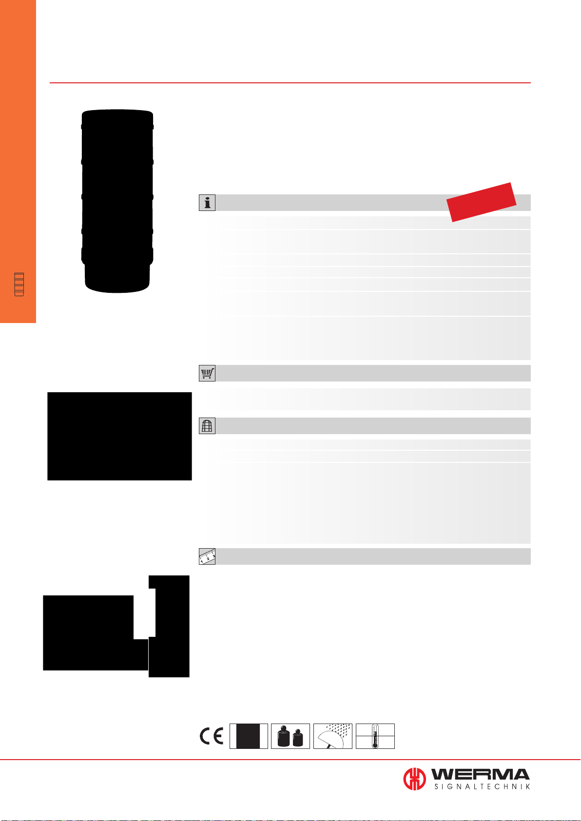
697 LED Signal Tower KOMPAKT 71
with USB Interface
KOMPAKT 71
•
completely
•
pre-assembled
Signal Towers
Completely pre-assembled
signal tower with integrated
USB terminal element
• Completely pre-assembled signal
tower with integrated USB terminal
element
• No additional voltage supply or
hardware is required
• Actuation via a DLL (Dynamic Link
Library) or VCP (Virtual-COM-Port)
• No additional power supply or
hardware necessary
• Direct triggering of signal tower via
USB Interface
TECHNICAL SPECIFICATIONS:
Dimensions (Ø x Height): 70 mm x 175 mm
Housing: Housing parts: PC
Terminal element: PA-GF, high-impact
Fixing: Tube mounting (accessory)
Connection: Via USB
Power supply: Via USB (5 V DC)
Assembly:
Assembly includes installation software, drivers, handbook
and USB connection cable (length 1.8 m)
Suitable for: Windows 2000 service pack 4, Windows XP, Windows
Vista or Windows 7. Also for Windows Server and
Windows CE operating systems.
ORDER SPECIFICATIONS:
Life duration
up to 50,000 hrs
The user-friendly demonstration
software is included in the assembly
3 tier red/yellow/green 697 430 53
ACCESSORIES:
Base with integrated tube 975 840 10
Base with tube, metal 975 840 91
Tube Ø 25 mm, all anodized aluminium
100 mm long 975 845 10
250 mm long 975 840 25
400 mm long 975 840 40
600 mm long 975 840 60
800 mm long 975 840 80
1000 mm long 975 840 03
TECHNICAL DIAGRAMS:
see page 312
Direct triggering via USB interface
(assembly without laptop
and accessories)
78
www.werma.com
See note
on page 347
300 g
IP 65
+50°C
-20°C
Page 80
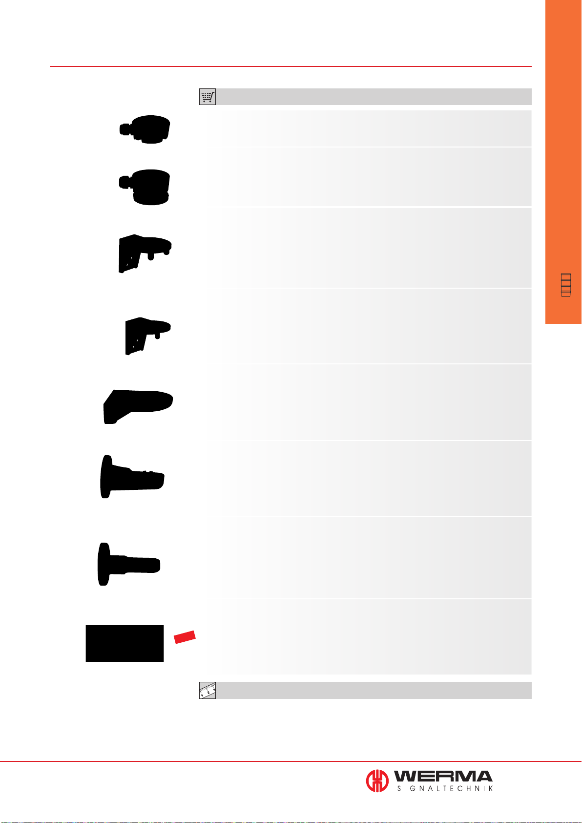
Accessories for KOMPAKT 71
ORDER SPECIFICATIONS ACCESSORIES KOMPAKT 71:
Contact box for Câble exit at side, 975 840 01
with mounting material
Contact box with magnetic base 975 840 04
and Câble exit at side
Bracket for tube mounting 960 000 01
with Câble gland
Bracket for surface mounting 960 698 05
with Câble gland
Accessories KOMPAKT 71
•
completely
•
pre-assembled
Signal Towers
Bracket for base mounting 960 000 14
with concealed Câble entry, incl. rubber seals
Bracket for 1-sided 975 840 85
mounting, incl. rubber seals
Bracket for 2-sided 975 840 86
mounting, incl. rubber seals
Corner fixing bracket 960 000 41
NEW
www.werma.com
TECHNICAL DIAGRAMS:
see page 327 onwards
79
Page 81
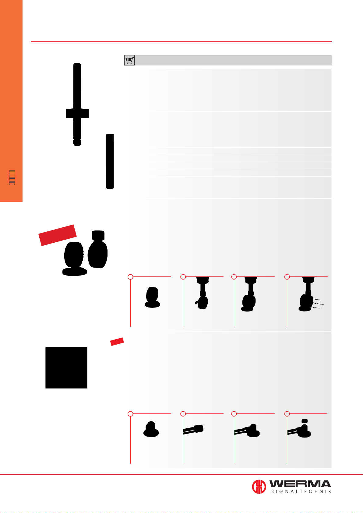
Accessories for KOMPAKT 71
Accessories KOMPAKT 71
•
completely
•
pre-assembled
Signal Towers
Utility model
approved
ORDER SPECIFICATIONS ACCESSORIES KOMPAKT 71:
Tube with clamp, Ø 25 mm 960 000 18
250 mm long, with Câble gland
Tube Ø 25 mm, all anodized aluminium
100 mm long 975 845 10
250 mm long 975 840 25
400 mm long 975 840 40
600 mm long 975 840 60
800 mm long 975 840 80
1000 mm long 975 840 03
Foldaway Base incl. rubber seals, suitable for tube, 960 000 30
Ø 25 mm, all anodized aluminium (not included in assembly)
Dimensions (Ø x Height): 70 mm x 117 mm
Material: PA-GF
Câble diameter: max. 14 mm
Assembly: incl. rubber seals
Fixing: Vertical, horizontal,
Positioning in 7.5° steps
QUICK AND SIMPLE MOUNTING:
1
Place the lower part of the
Foldaway Base in the desirouge position
NEW
Foldaway Base incl. rubber seals, suitable for tube, 960 009 12
2
Attach the upper part directly
onto the signal tower tube.
Insert the Connexion Câble
3
Place the upper and lower
parts together at the desirouge angle
Ø 25 mm, all anodized aluminium (not included in assembly)
Dimensions (Ø x Height): 70 mm x 85 mm
Material: PA-GF
Câble diameter: max. 8 mm
Assembly: incl. rubber seals
Fixing: Vertical, horizontal,
Positioning in 0° and 90°
QUICK AND SIMPLE MOUNTING:
1
2
3
4
Place the upper and lower
parts together at the desirouge angle
4
80
www.werma.com
Place the „foldaway“ base
in the desirouge mounting
position
Attach the tube adaptor
directly to the signal tower
and introduce the Câble
Fix the whole assembly - tube
adaptor and signal tower, in
the desirouge position, vertically or horizontally - onto the
foldaway base
Place the cover on the
other open end
Page 82
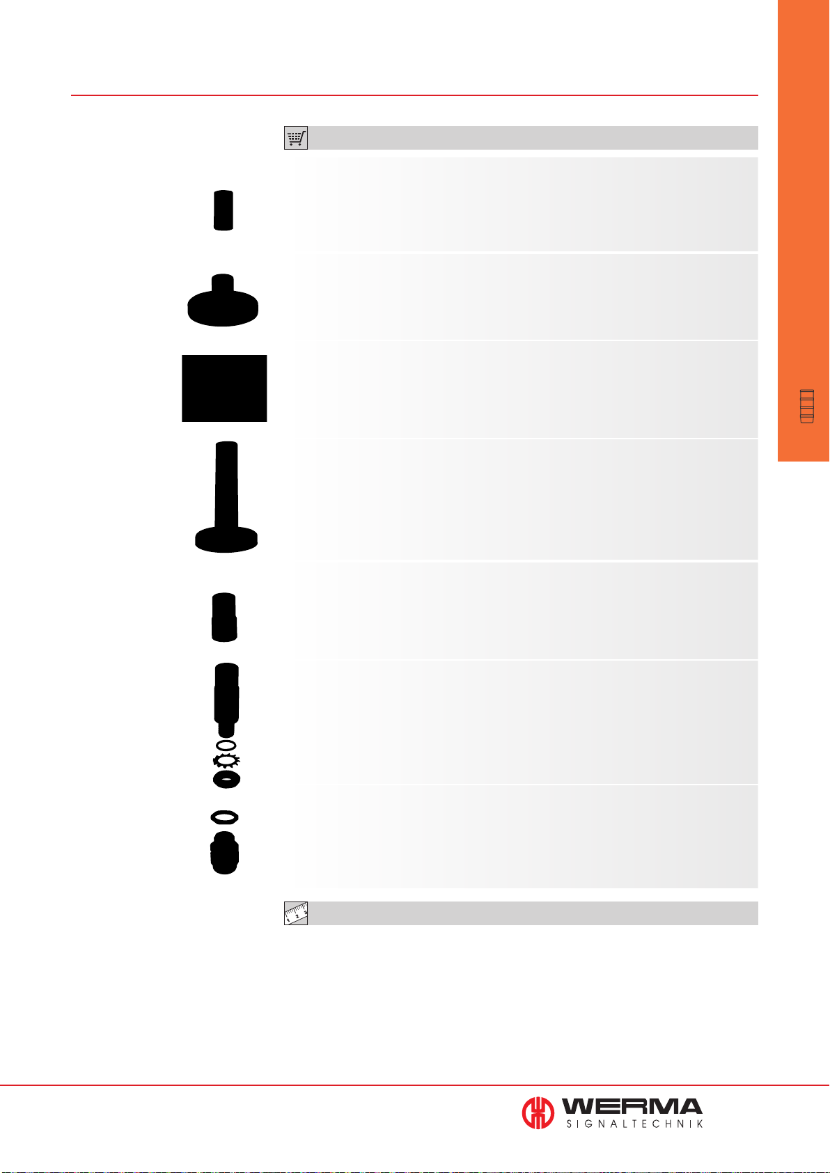
ORDER SPECIFICATIONS ACCESSORIES KOMPAKT 71:
Tube Ø 25 mm, plastic 960 000 31
for mounting the Terminal Element directly
on the Foldaway Base
Base for tube mounting Ø 25 mm, 975 840 90
plastic, incl. rubber seal
Base for tube mounting Ø 25 mm, metal, incl. rubber seal, 975 840 91
recommended for tube lengths of 400 mm and longer
Base with integrated tube, Ø 25 mm, 975 840 10
110 mm long, plastic, incl. rubber seal
Accessories KOMPAKT 71
•
completely
•
pre-assembled
Signal Towers
Adaptor for tube mounting, 975 840 02
Ø 25 mm / 1/2” NPT thread
Adaptor for single hole mounting 960 000 25
Ø 25 mm, M18
NEW
Câble gland for 960 000 04
surface mounting M16 x 1.5 mm
TECHNICAL DIAGRAMS:
see page 327 onwards
www.werma.com
81
Page 83
deSIGN 42
deSIGN 42 - LED Signal Tower with
high-quality stainless steel housing
deSIGN
•
completely
•
pre-assembled
Signal Towers
In the machine building sector
a trend towards a greater emphasis
on design has become apparent.
The design of a machine and its
accessories convey the manufacturer’s
quality statement to the customer.
Form, colour and aesthetics are
increasingly being borne in mind
as purchasing criteria.
The LED signal tower deSIGN 42, with
its high quality stainless steel housing
is an ideal accompaniment to modern
design-oriented machines, uniquely
combining cool elegance with optimal
functionality. With its innovative form,
the stainless steel housing underscores
the design of the customer product,
stylishly harmonising with its overall
appearance.
82
The advantages at a glance
LED Signal Tower in award-winning metal design
Clear lenses ensure signalling effect even in
direct sunlight
LED Permanent light elements have a life duration
of up to 50,000 hrs
Can be operated with a PLC control system
www.werma.com
Page 84
694 LED Signal Tower deSIGN 42
• High-quality stainless steel housing
• Award-winning design
• Transparent lenses ensure
signalling effect even in direct
sunlight
TECHNICAL SPECIFICATIONS:
Dimensions (Ø x Height): 2 tier: 42 x 220 mm
3 tier: 42 x 254 mm
Housing: Stainless steel, brushed
Fixing: Installation mounting for Ø 22.5 mm (M22 x 1.5 mm)
Connection: Cable, 2 m long, included in assembly
Current consumption: 40 mA per tier
ORDER SPECIFICATIONS:
deSIGN 24 V DC
2 tier red/green 694 010 55
red/yellow 694 020 55
3 tier red/yellow/green 694 000 55
ACCESSORIES:
Life duration
up to 50,000 hrs
deSIGN
•
completely
•
pre-assembled
Signal Towers
Surface housing single 975 109 02
Bracket, stainless steel (Protection rating IP 33) 960 694 01
TECHNICAL DIAGRAMS:
see page 311
www.werma.com
See note
on page 347
2 tier 3 tier
600 g 650 g
IP 65
+50°C
-20°C
PLC
83
Page 85
FlatSIGN
FlatSIGN
•
completely
•
pre-assembled
Signal Towers
Innovative LED Signal Tower with curved front
The LED signal tower FlatSIGN stands out from the competition with its range of innovative
functions and unique advantages: in particular its aesthetically pleasing, curved design
which facilitates a 160° viewing angle. This guarantees exceptional signal visibility, even
from the side.
If no signal is active, the flat LED signal tower blends into the background - without
distracting from the design of the machine or its environment.
Wide range of applications
The FlatSIGN can be deployed in a wide range of applications: from logistics, warehousing and materials handling to machine and plant engineering. Thanks to its high build
quality and appearance it is also ideally suited for building services applications. The
high protection rating IP 65 ensures it can also be used outside.
The advantages at a glance
Permanent or blinking light selectable
High build quality and appearance
160° viewing angle - the signal is clearly visible
from the side
Also available with integrated loud audible signal
(depending on the variant, either a buzzer or multi-tone sounder)
Multi-Tone Sounder with 8 adjustable tones
Flexible, user-friendly mounting options and simple connection
Comprehensive fixing kit available as accessory
84
www.werma.com
Page 86
691 FlatSIGN
In its inactive state, the signal tower
blends into the background thanks to
its colourless, translucent housing
• Innovative LED signal tower with
curved front
• 160° signal visibility - the signal
is transparently visible from the
side
• Permanent or blinking light
• With optional integrated,
high-output buzzer
• Simple, user-friendly mounting
• Comprehensive fi xing kit for a
wide range of mounting options
(accessory)
selectable
TECHNICAL SPECIFICATIONS:
Dimensions (L x H x W): 195 mm x 105 mm x 48.2 mm
Lower part: PC-ABS, black
Upper part: PC, transparent or silver
Lens: PC, transparent
Fixing: Wall mounting
Connection: Screw terminal max. 1.5 mm
Current consumption: Optical signal: 30 mA per tier
Audible signal: 30 mA
Light effects: Permanent or blinking light selectable
Audible signal: Buzzer or multi-tone sounder (8 tones)
ORDER SPECIFICATIONS:
Voltage 24 V DC 115-230 V AC
Audibel Signal Multi-tone Sounder Buzzer
FlatSIGN with transparent housing
FlatSIGN without audible signal, red/yellow/green 691 100 55 691 100 68
FlatSIGN with audible signal, red/yellow/green 691 200 55 691 200 68
Life duration
up to 50,000 hrs
2
FlatSIGN
•
completely
•
pre-assembled
Signal Towers
FlatSIGN in metallic finish
The fixing kit consists of two
tube clamps and an adaptor
(accessory)
FlatSIGN in Metal Design
FlatSIGN without audible signal, red/yellow/green 691 300 55 691 300 68
FlatSIGN with audible signal, red/yellow/green 691 400 55 691 400 68
ACCESSORIES:
Fixing kit 975 691 01
Contents: 2 tube clamps for tube
(Ø 24-25 mm) and adaptor
No special accessories needed for mounting on a fl at surface.
FlatSIGN is ideal for mounting on fl at surfaces such as walls or enclosures.
The comprehensive fi xing kit, available as an accessory, permits more mounting options.
• If the signal tower is to be connected via surface wiring, then it can be simply attached
using the adaptor.
• The adaptor also enables the tower to be quickly and simply mounted onto electrical
installation back-boxes.
• In addition, the adaptor enables simple mounting onto aluminium profi les.
• For tube mounting (Ø 24-25 mm) the adaptor and the two tube clamps are employed.
TECHNICAL DIAGRAMS:
See note
on page 347
see page 311
235 g
IP 65
+50°C
-30°C
80 dB
691 X00 55
8
www.werma.com
85
Page 87
VarioSIGN
VarioSIGN
•
completely
•
pre-assembled
Signal Towers
VarioSIGN - Innovative signal towers with unique
functions and a range of advantages
The LED signal tower VarioSIGN stands out from the competition with
its range of unique features and advantages as well as its revolutionary, innovative form.
If no signal is active, the LED tower blends into the background with its
colourless, translucent housing - without distracting from the design
of the machine. Only in the event of an active signal is the tower filled
with colour, making its presence known with its large, attention-grabbing illuminated surface.
Thus the signal tower combines a maximum optical effect with modern
machine forms and designs.
The advantages at a glance
Mechanical modularity of the three tiers replaced by electronic
modularity
Colours and light effects, depending on the variant, can be
individually set via DIP switch and changed at any time
High build quality and appearance
Award-winning design
Light effect visible from one or two sides as required
With optional integrated, high output buzzer
Variants available with adjustable, attention-grabbing lighting effects
86
www.werma.com
Page 88
690 VarioSIGN - red/yellow/green
German utility
model approved
Fixed, three-tier colour
distribution in red, yellow
and green
• LED signal tower with permanent
lights in red, yellow and green
• Preset, three-tier colour
• 1 or 2 sided illumination
• With optional integrated,
high output buzzer
distribution
TECHNICAL SPECIFICATIONS:
Dimensions (L x H x W): 62 mm x 220 mm x 90 mm
Housing: PC/ABS-Blend, black
Lens: PC, transparent
Fixing: Base mounting
Connection: Screw terminal max. 1.5 mm
Current consumption: Optical: 55 mA per tier
Buzzer: 20 mA
ORDER SPECIFICATIONS:
Voltage 24 V DC
VarioSIGN without Buzzer
1-sided 690 330 55
2-sided 690 320 55
VarioSIGN
Life duration
up to 50,000 hrs
2
•
completely
•
pre-assembled
Signal Towers
In its inactive state, the signal
tower blends into the background
thanks to its colourless, translucent
housing
VarioSIGN with Buzzer
1-sided 690 310 55
2-sided 690 300 55
ADDITIONAL INFORMATION:
Mounting positions
Depending on the application, the lighting body of the VarioSIGN signal tower can be
positioned to point upwards, downwards or horizontally.
Lighting body positioned upwards Lighting body positioned downwards
TECHNICAL DIAGRAMS:
see page 311
www.werma.com
See note
on page 347
240 g
IP 65
+50°C
-30°C
85 dB
87
Page 89
690 VarioSIGN - RGY
model approved
VarioSIGN
•
completely
•
pre-assembled
Signal Towers
German utility
The colours red, yellow and
green can adjusted via DIP
switch for any required order
or distribution
• LED signal tower with permanent
lights in red, yellow and green
• Complete illumination in one
colour possible (can be
triggered externally)
• Colour distribution can be set
and adjusted as required via DIP
switch
• With optional integrated,
high output buzzer
TECHNICAL SPECIFICATIONS:
Dimensions (L x H x W): 62 mm x 220 mm x 90 mm
Housing: PC/ABS blend, black
Lens: PC, transparent
Fixing: Base mounting
Connection: Screw terminal max. 1.5 mm
Current consumption: Optical:
depending on the colour combination, up to 120 mA
Buzzer: 20 mA
ORDER SPECIFICATIONS:
Voltage 24 V DC
VarioSIGN without Buzzer
1-sided 690 230 55
2-sided 690 220 55
Life duration
up to 50,000 hrs
2
Attention-grabbing illumination
of the entire lighting body in
one colour (can be triggered
externally)
VarioSIGN with Buzzer
1-sided 690 210 55
2-sided 690 200 55
ADDITIONAL INFORMATION:
Adjustable lighting configuration and mounting positions
Lighting body positioned
upwards
Tier-by-tier illumination of the
lighting body
Lighting body positioned
downwards
Colour intensive, complete
illumination
Depending on the application, the lighting body of the
VarioSIGN signal tower can be
positioned to point upwards,
downwards or horizontally.
Depending on the variant, a
tier-by-tier or complete illumination of the lighting body is
possible.
88
www.werma.com
TECHNICAL DIAGRAMS:
See note
on page 347
260 g
see page 311
+50°C
IP 65
-30°C
85 dB
Page 90
690 VarioSIGN - RGB
German utility
model approved
Attention-grabbing illumination
of the entire lighting body in
one colour (a choice of 7 colours,
can be triggered externally)
• LED signal tower with permanent
light and additional light effects
• 7 colours
• Complete illumination in one
colour possible (can be
• Colour distribution can be set
and adjusted as required via DIP
switch
• With integrated, high output
buzzer
triggered externally)
TECHNICAL SPECIFICATIONS:
Dimensions (L x H x W): 62 mm x 220 mm x 90 mm
Housing: PC/ABS blend, black
Lens: PC, transparent
Fixing: Base mounting
Connection: Screw terminal max. 1.5 mm
Current consumption: Optical: depending on the colour, up to 300 mA max.
Buzzer: 20 mA
Possible colours: Red, yellow, green, white, blue, violet, turquoise
Lighting effects: Tier-by-tier illumination: Flashing light
Complete illumination: EVS*
2
ORDER SPECIFICATIONS:
Life duration
up to 50,000 hrs
VarioSIGN
•
completely
•
pre-assembled
Signal Towers
Patent
approved
The “EVS“* light effect ensures
a maximum attention-grabbing
effect (can be set with complete
illumination)
Voltage 24 V DC
VarioSIGN with light effects and Buzzer
1-sided 690 010 55
2-sided 690 000 55
ADDITIONAL INFORMATION:
* EVS = Enhanced Visibility System
Further Information can be found in the chapter ”General Information“ on page 352.
Please note the photosensitive epilepsy warning on page 352.
Adjustable lighting confi guration and mounting positions
Depending on the application, the lighting body of the VarioSIGN signal tower can be
positioned to point upwards, downwards or horizontally (see page 88).
Depending on the variant, a tier-by-tier or complete illumination of the lighting body is
possible (see page 88)
TECHNICAL DIAGRAMS:
see page 311
See note
on page 347
260 g
IP 65
+50°C
-30°C
85 dB
www.werma.com
89
Page 91
CleanSIGN
CleanSIGN
•
completely
•
Hygienic Design
CleanSIGN - The LED Signal Tower in Hygienic Design
WERMA already has the appropriate solution to the challenges engineers and food manufacturers
will have to face in the future: The LED signal tower CleanSIGN has been specially developed and
constructed for use in food and hygiene areas as well as cleanroom applications. Right from the
start, existing standards and guidelines were given careful consideration (e.g. EHEDG* Documents
8 and 13, Machine Directive 2006/42/EG), and experts in the field of Hygienic Design were called
upon for advice.
The CleanSIGN is equipped with a series of sophisticated technical, constructional and design
features which make a significant contribution to the safety of your products.
pre-assembled
Signal Towers
What is Hygienic Design?
The term, ”Hygienic Design“, stands for the hygienic and cleaning-friendly design of all machinery
and components deployed in hygiene-relevant areas. The aim is the prevention of constructional
weakspots that could increase hygiene-related dangers and the risk of infection.
What are the main applications?
In addition to use in food production, manufacturing processes in clean rooms are also potential
application areas. The production and assembly of small and very sensitive parts such as electronic
chips places the highest demands on air purity.
As the CleanSIGN LED Signal Tower fulfils the high Air Cleanliness Class 1 or 2 (depending on
version), it can be used in the semiconductor industry, microelectronics, medical research, pharmaceutical, optical and laser technology, aerospace engineering and nanotechnology.
90
www.werma.com
The key advantages
Food safety due to the absence of uneven surfaces, elevated or countersunk
elements where contamination could collect
Cleaning-friendly and hygienic design for optimal cleaning and
disinfection
Use of food safe materials (FDA approval) and resistant to cleaning
agents
EHEDG* and Fraunhofer approvals
Bracket mounting fulfills Air Cleanliness Class 2 for Cleanroom
applications in accordance with DIN EN ISO 14644-1
Base or Ceiling mounting fulfills
Air Cleanliness Class 1
®
Bracket mounting with Pine Tree Clip
for quick and simple fixing
Electronic modularity of the individual tiers
Maintenance-free thanks to LED technology with a long life duration of up to
50,000 hrs
Page 92
695 CleanSIGN - red/yellow/green
Fixed, three tier colour distribution
in red, yellow and green
• LED Signal Tower for use in cleanroom applications (Fraunhofer IPA
approval) and the food industry
(EHEDG* approval)
TECHNICAL SPECIFICATIONS:
• Permanent lights in red, yellow
and green
• Integrated, high output
buzzer (85 dB)
Life duration
up to 50,000 hrs
Dimensions (L x H x W): Bracket mounting: 112 mm x 485 mm x 125 mm
Base mounting: 112 mm x 391 mm x 125 mm
Housing: PA, black
Lens: PA, transparent
Fixing: Wall mounting, integrated mounting bracket
Base mounting, Ceiling mounting
Connection: Cable, 2 m long, included in the assembly
Current consumption: Optical: up to 120 mA per tier
Buzzer: 20 mA
ORDER SPECIFICATIONS:
Voltage 24 V DC
SIGN
Clean
Bracket mounting 695 300 55
Base or Ceiling mounting 695 310 55
with Buzzer
CleanSIGN
•
completely
•
pre-assembled
Signal Towers
Air Cleanliness
Class 1
In its inactive state, the signal tower
blends into the background thanks
to its translucent housing
ADDITIONAL INFORMATION:
•
Fraunhofer IPA approval for cleanrooms: enables the Clean
SIGN
to be used in the most
demanding Air Cleanliness Classes in accordance with DIN EN ISO 14644-1 and therefore
covers even the most sensitive cleanroom applications. This approval also confirms the chemical resistance of the signal tower housing against common cleaning agents.
• EHEDG* approval for the food industry: this approval confirms that strict design criteria
have been met to avoid constructional weaknesses and to minimise the risk of contamination.
* EHEDG = European Hygienic Engineering and Design Group
The goal of this consortium, made up of equipment
manufacturers, food processing industries, research
institutes and public health authorities, is the
development and publishing of directives on
hygiene technology for the processing and
packaging of food products.
TECHNICAL DIAGRAMS:
see page 311
Fixed colour distribution
with SMD technology
www.werma.com
See note
on page 347
695 300 55 695 310 55
550 g 530 g
IP 67/
IP 69k
+50°C
85 dB
-30°C
91
Page 93
695 CleanSIGN - RGY
CleanSIGN
•
completely
•
pre-assembled
Signal Towers
The colours red, yellow and green
can be set via DIP switch for any
equired order or distribution
• LED Signal Tower for use in cleanroom applications (Fraunhofer IPA
approval) and the food industry
(EHEDG approval)
• Permanent light in red, yellow
and green (RGY LEDs)
• Colour distribution can be set and
adjusted via switch as required
• Complete illumination in one colour
possible (can be triggered
externally)
• Integrated, high output buzzer
(85 dB)
TECHNICAL SPECIFICATIONS:
Dimensions (L x H x W): Bracket mounting: 112 mm x 485 mm x 125 mm
Base mounting: 112 mm x 391 mm x 125 mm
Housing: PA, black
Lens: PA, transparent
Fixing: Wall mounting, integrated mounting bracket
Base mounting, Ceiling mounting
Connection: Screw terminal max. 1.5 mm
Current consumption: Optical:
depending on the colour combination, 240 mA max.
Buzzer: 20 mA
ORDER SPECIFICATIONS:
2
Life duration
up to 50,000 hrs
Air Cleanliness
Class 1
Attention-grabbing illumination
in one colour (can be triggerouge
externally)
Voltage 24 V DC
SIGN
Clean
with Buzzer
Bracket mounting 695 200 55
Base or Ceiling mounting 695 210 55
ADDITIONAL INFORMATION:
Clever solution for wall mounting
A “Pine Tree Clip
tower is carried out from the rear. As a consequence, the housing is completely closed and
holes are avoided.
Wide range of sophisticated design features
The CleanSIGN from WERMA is equipped with a series of sophisticated technical,
constructional and design features which make a signifi cant contribution to the safety
of your products.
For example, the CleanSIGN has no grooves or joints
where dirt could collect, facilitating quick and easy
cleaning.
®
” enables quick and simple mounting. The attachment and connection of the
TECHNICAL DIAGRAMS:
see page 311
92
www.werma.com
See note
on page 347
695 200 55 695 210 55
420 g 400 g
Completely flexible colour
distribution thanks to RGY LEDs
IP 67/
IP 69k
+50°C
85 dB
-30°C
Page 94
695 CleanSIGN - RGB
Complete illumination
in one colour
• LED Signal Tower for use in cleanroom applications (Fraunhofer IPA
approval) and the food industry
(EHEDG approval)
• Permanent light and additional
light effects
• 7 colours selectable
• Colour distribution can be set and
adjusted via switch as required
• Complete illumination in one colour
possible (can be triggered
externally)
• Integrated, high output buzzer
(85 dB)
TECHNICAL SPECIFICATIONS:
Dimensions (L x H x W): Bracket mounting: 112 mm x 485 mm x 125 mm
Base mounting: 112 mm x 391 mm x 125 mm
Housing: PA, black
Lens: PA, transparent
Fixing: Wall mounting, integrated mounting bracket
Base mounting, Ceiling mounting
Connection: Screw terminal max. 1.5 mm
Current consumption: Optical: depending on the colour combination,
250 mA max.
Buzzer: 20 mA
Possible colours: Red, yellow, green, white, blue, violet, turquoise
Light effects: Tier-by-tier illumination: Blinking light
Complete illumination: EVS*
Life duration
up to 50,000 hrs
2
CleanSIGN
•
completely
•
pre-assembled
Signal Towers
Air Cleanliness
Class 1
The “EVS“* light effect ensures
a maximum attention-grabbing
effect (can be set with complete
illumination)
ORDER SPECIFICATIONS:
Voltage 24 V DC
SIGN
Clean
with Buzzer
Bracket mounting 695 000 55
Base or Ceiling mounting 695 010 55
ADDITIONAL INFORMATION:
Additional light effects and 7 colours
The use of RGB LEDs guarantees complete fl exibility: In addition to the permanent
light, additional light effects (EVS* LED or blinking light) can also be set. Furthermore,
the entire tower or the 3 individual tiers can be illuminated in seven different colours
(red, yellow, green, blue, clear, violet, turquoise).
With complete illumination any one of the seven colours can be
triggered externally.
* EVS = Enhanced Visibility System or Enhanced Visibility
System. Further Information can be found in the chapter
„General Information“ beginning on page 352.
Please note the photosensitive epilepsy warning
on page 352.
TECHNICAL DIAGRAMS:
see page 311
See note
on page 347
695 000 55 695 010 55
420 g 400 g
7 different colour settings
from RGB LEDs
IP 67/
IP 69k
+50°C
-30°C
85 dB
www.werma.com
93
Page 95

Optical Signal Devices
Installation Beacons
Page 96
Overview Installation Beacons
LED Permanent Beacons
230 and
230 Economy
M20 x 1.5 mm
Page 98
231 and
231 Economy
M22 x 1.5 mm
Page 100
207
M22 x 1.5 mm
Page 105
LED Permanent Beacons (Multicolour)
239 Multicolour 816 Multicolour
NEW
M22 x 1.5 mm
5 colours
Page 102
239 for
AS-Interface
M22 x 1.5 mm
5 colours
Page 103
NEW
with M12 plug
for Ø 37 mm (PG29)
7 colours
Page 111
Permanent Beacons
801
for Ø 37 mm (PG29)
Page 108
NEW
816 multicolour
with USB Interface
for Ø 37 mm (PG29)
200,000 colours
Page 112
816
for Ø 37 mm (PG29)
Page 117
Optical Signal Devices
Installation Beacons
206
M22 x 1.5 mm
Page 104
216
M22 x 1.5 mm
Page 106
Flashing Beacons
232
M22 x 1.5 mm
Page 113
208
M22 x 1.5 mm
Page 114
800
for Ø 37 mm (PG29)
Page 107
802
for Ø 37 mm (PG29)
Page 115
815
for Ø 37 mm (PG29)
Page 109
817
for Ø 37 mm (PG29)
Page 116
LED Blinking
Light
816
for Ø 37 mm (PG29)
Page 117
Bulbs
LED Bulbs Page 182 + 183
Bulb Overview Page 184 + 185
www.werma.com
Further information
Further information about “Optical Signal Devices” can be found
in the chapter “General Information” beginning on page 356.
95
Page 97
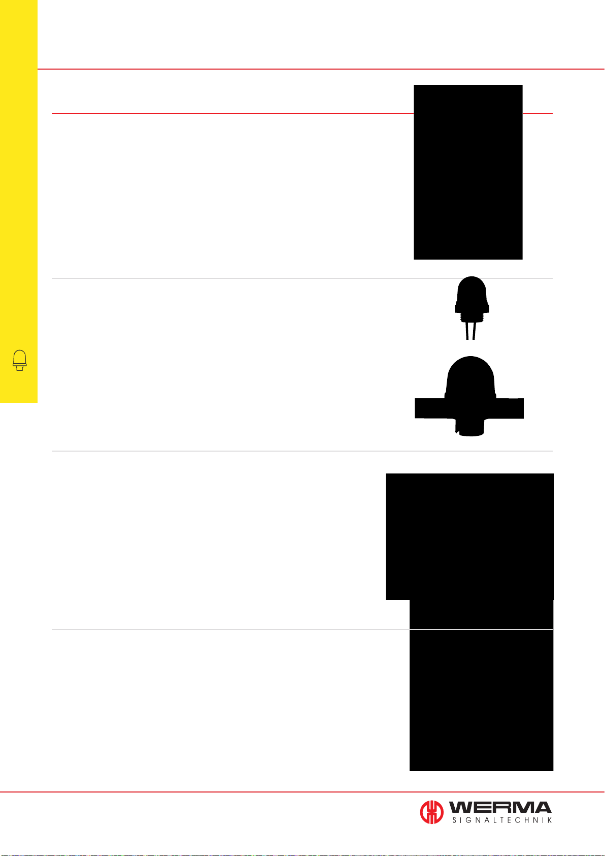
Optical Signal Devices
Variety of light signals
Installation beacons from WERMA assist in indicating process conditions, risks and
imminent dangers in modern production areas clearly and in good time.
The urgency of the required course of action can be indicated by the colour as well
as the type and duration of the signal. As a basic principle, the colours red, yellow,
green, blue and clear are employed. The available light effects in WERMA installation
beacons range from a permanent light and a long life LED permanent light to an
attention-grabbing fl ashing light.
Overview
•
Permanent light and LED Permanent light
With the assistance of a permanent light or an LED permanent light the operator is
Optical Signal Devices
made aware of a specifi c condition or is instructed to carry out a certain course of action.
Installation Beacons
For safety reasons signal beacons are increasingly equipped with light emitting diodes. The
failure of optical signal devices is signifi cantly reduced as a result of the longer life duration
of LEDs. Furthermore, LEDs offer a range of advantages compared to conventional light bulbs for example lower current consumption, greater resistance to shocks, vibrations and other mechanical stress.
LED Beacons (Multicolour)
As well as offering traditional single coloured beacons, Werma has several multicolour LED
products which give the user multiple colour choices in just one beacon.
The 816 LED beacon with USB connection uses RGB LED technology from which you can
select up to 200,000 colour variants also in different light effects, such as permanent, blink
or special fl ash.
The LED multicolour beacons 239 and 816 with M12 connectors offer up to 7 colours and
enable you to signal several different status conditions with just one beacon.
Flashing Light
The deployment of a fl ashing signal can generate even more attention than a permanent
light. The reason for this is to be found in the very short fl ash duration.
Inside each Xenon fl ashing beacon there is a capacitor which stores electrical energy.
Within the space of a few milliseconds this energy is discharged within the fl ash tube, generating a very intense light impulse.
The life duration of a fl ash tube is heavily dependent on the respective load.
The average life duration in permanent operation is 4 x 10
6
fl ashes.
96
www.werma.com
Page 98
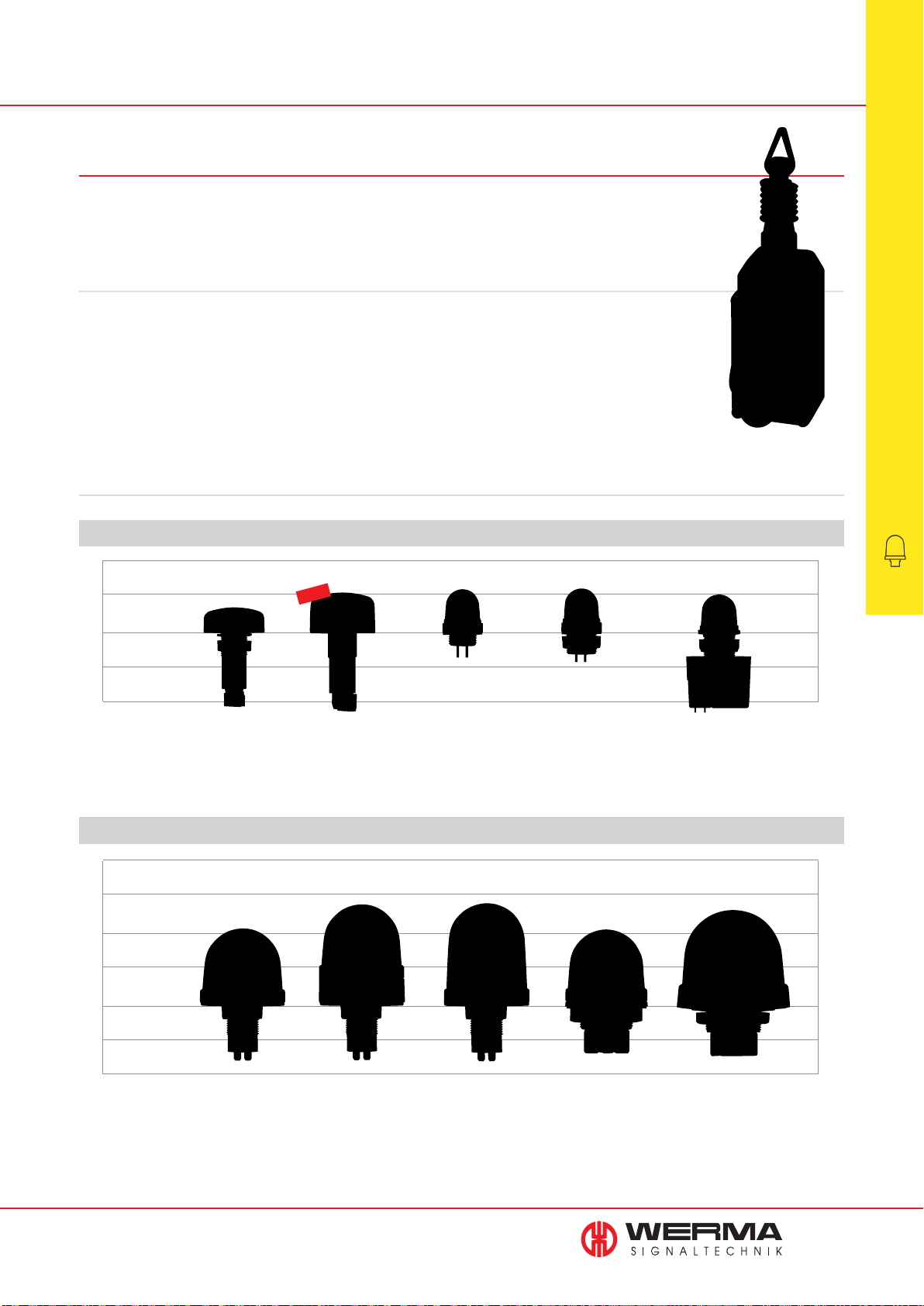
WERMA Installation Beacons
Installation beacons are designed for mounting in drill holes. A characteristic of this type of
beacon is the rear fixture using a central nut.
Advantages
• Large variety of versions: Available as permanent,
blinking, flashing or LED beacons
• IP 65 for indoor and outdoor applications
• Modern design
• Beacons available in five colours
Sizes
COMPARISON OF WERMA INSTALLATION BEACONS
50
NEW
0
Series
Thread
Ø
Height
Page
(Protrusion from panel)
239
M22
50 mm
22 mm
103
239
M22
50 mm
31 mm
102
• LED Multicolour Beacons with 5 or up to
200,000 colours in one beacon
• Beacon diameter between 25 and 75 mm
• Available in three thread diameters
230
M20
29 mm
32 mm
98
231
M22
29 mm
32 mm
100
232
M22
29 mm
32 mm
113
Overview
•
Optical Signal Devices
Installation Beacons
50
0
COMPARISON OF WERMA INSTALLATION BEACONS
100
50
0
Series
Thread
Ø
Height
(Protrusion from panel)
Page
www.werma.com
206
M22
57 mm
53 mm
104
207/208
M22
58 mm
69 mm
105/114
216
M22
57 mm
69 mm
106
800/801/802
PG29
57 mm
54 mm
107/108/115
100
50
0
815/816/817
PG29
75 mm
66 mm
109/116/117/111/112
97
Page 99
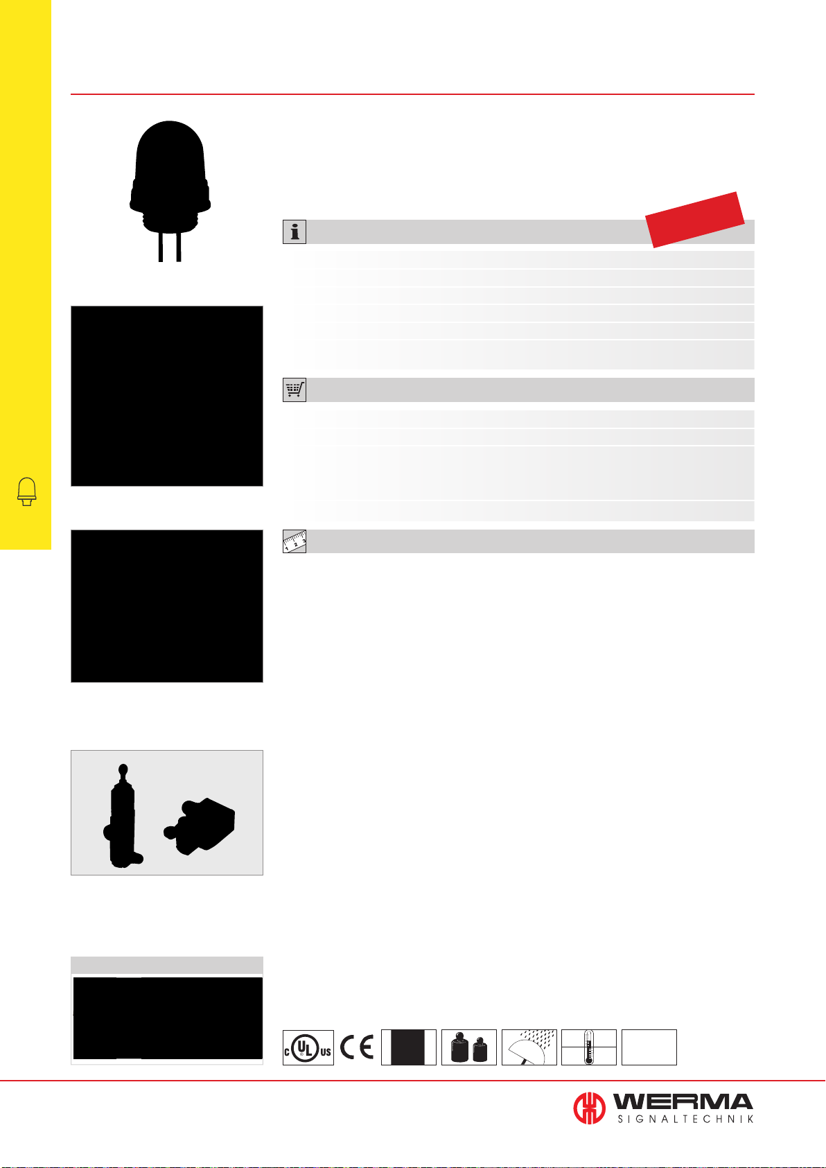
230 LED Installation Beacon
Permanent Beacons
•
Optical Signal Devices
Installation Beacons
Mainly sidewards illumination
• LED Permanent beacon with
M20 thread for applications such
as limit and cable-operated
• Extremely high light intensity
• Ideal for installation in limited
space due to short thread
switches
TECHNICAL SPECIFICATIONS:
Dimensions (Ø x Height): 29 mm x 32 mm (Protrusion from panel)
Housing: PC/ABS-Blend
Lens: PC, transparent
Connection: 2 wires, c. 115 mm long
Fixing: Installation mounting for Ø 20.5 mm (M20 x 1.5 mm)
Seal included in assembly.
ORDER SPECIFICATIONS:
Voltage 12 V DC 24 V DC 115 V AC 230 V AC
Current consumption 80 mA 45 mA 15 mA 20 mA
red 230 100 54 230 100 55 230 100 67 230 100 68
yellow 230 300 54 230 300 55 230 300 67 230 300 68
clear - 230 400 55 - Further colours on request.
Life duration
up to 100,000 hrs
Illustration of the light distribution for
the LED Installation Beacon 230
The LED Installation Beacon 230 can
for example be used in applications
with cable-operated switches or limit
switch devices
TECHNICAL DIAGRAMS:
see page 302
Sizes of Permanent Beacons
98
www.werma.com
See note
on page 347
12 g
IP 65
+50°C
-20°C
24 V
PLC
Page 100
230 Economy LED Installation Beacon
• Innovative LED technology with
upward illumination
• Ideal for installation in limited
• LED Permanent Beacon with M20
thread for the limit and
cable-operated switches
space due to short thread
TECHNICAL SPECIFICATIONS:
Dimensions (Ø x Height): 29 mm x 32 mm (Protrusion from panel)
Housing: PC/ABS-Blend
Lens: PC, transparent
Connection: 2 wires, c. 115 mm long
Fixing: Installation mounting for Ø 20.5 mm (M20 x 1.5 mm)
Seal included in assembly.
ORDER SPECIFICATIONS:
Voltage 24 V DC
Current consumption 30 mA
red 230 104 55
yellow 230 304 55
clear 230 404 55
Life duration
up to 100,000 hrs
Permanent Beacons
•
Optical Signal Devices
Installation Beacons
Upward illumination
upwards
sidewards sidewards
Illustration of the light distribution for
the Economy LED Installation Beacon
230
ADDITIONAL INFORMATION:
LED Installation Beacon 230 Economy attains an
extremely high level of visibility thanks to completely
new LED technology with upward illumination.
This innovative solution draws upon the most advanced technology and is furthermore resistant to vibration and other mechanical stress.
The LED Beacon 230 has a short M20 thread
and is especially suitable for installation in small
spaces such as cable-operated switches or
limit switches.
TECHNICAL DIAGRAMS:
see page 302
Sizes of Permanent Beacons
www.werma.com
12 g
IP 65
+50°C
-20°C
PLC
99
 Loading...