

Page 1

Welltech 2424s FXS
Gateway User Guide
Page 2

2
Contents
CH1 Introduction .............................................................................. 4
1-1 Physical Interface ............................................................................. 4
1-2 Environmental .................................................................................. 4
1-3 Front Panel: LED Indicators .......................................................... 5
1-4 Rear Panel: LED Indicators ........................................................... 6
1-5 QUICK SETUP ................................................................................ 7
CH2 Devic e Settings ....................................................................... 13
2-1 Network Configuration ................................................................... 13
2-2 Device Time Setting ....................................................................... 15
2-3 Device Advance Setting.................................................................. 16
2-4 User Login Setting .......................................................................... 17
2-5 Debug Settings ................................................................................ 18
2-6 Event Notice ................................................................................... 19
2-7 Auto Provisioning ........................................................................... 20
2-8 SNMP ............................................................................................. 22
CH3 NAT Setting ............................................................................. 23
3-1 DHCP Ser. (DHCP server) .............................................................. 23
3-2 UPNP (universal plug and play server) .......................................... 24
3-3 Bandwidth (Bandwidth Control) .................................................... 24
3-4 URL Filter ....................................................................................... 28
3-5 IP Filter ........................................................................................... 28
3-6 MAC Filter ..................................................................................... 29
3-7 APP Filter ........................................................................................ 29
3-8 Port Filter ........................................................................................ 30
3-9 Port Fwd ......................................................................................... 30
CH4 V O IP Setting ........................................................................... 31
4-1 SIP .................................................................................................. 31
4-2 Audio .............................................................................................. 32
4-3 Tone ................................................................................................ 34
4-4 NAT Traversal ................................................................................. 35
CH5 VO IP Advance ........................................................................ 36
Page 3

3
5-1 SIP .................................................................................................. 36
5-2 Audio .............................................................................................. 38
5-3 Ring ................................................................................................ 40
CH6 Dialing Plan............................................................................ 41
6-1 General............................................................................................ 41
6-2 Dialing Rule .................................................................................... 42
6-3 Digit Manipulation ......................................................................... 43
6-4 Phone Book..................................................................................... 44
CH7 FXS Setting ............................................................................. 45
7-2 SIP Proxy ........................................................................................ 48
7-3 Caller ID ......................................................................................... 49
7-4 Others.............................................................................................. 50
CH8 SIP Trunk ................................................................................ 51
8-1 Create SIP Trunk ............................................................................. 52
CH9 Route Plan ............................................................................... 54
9-1 Create Route Plan ........................................................................... 55
CH10 Status ...................................................................................... 57
10-1 Device States ................................................................................ 57
10-2 Line States .................................................................................... 58
10-3 SIP Trunk States............................................................................ 59
CH11 Maintenance ......................................................................... 60
11-1 Firmware Update .......................................................................... 60
Appendix A--- System Recovery .......................................................... 61
Appendix B --- HTTP auto provisioning .............................................. 65
Page 4

4
WellGate 2424s
CH1 Introduction
2424s Telephony Gateway
The Welltech 2424s is a 24 ports FXS (WellGate 2424s) VoIP gatewa y which
includes 1-WAN/1-LAN (management port) 10/100 base-T network
environ m ent. Field-proven quality of Voice communica tion and Fax
transmis sion over IP broadband access network to makes WellGate 2424s to
be an exc elle nt solution for various VoIP applications.
1-1 Physical Interface
Ethernet port ( RJ-45, 10/100 base-T)
1-WAN port, for conn ect to router, ADSL modem (A TU-R), or switch
hub directly.
1-LAN port, for PC, management or other n e twork devices
connecting.
Telephony port (RJ-11)
24-FXS ports, to connec t to analog phone.
Console port (RS232, rate:115200)
AC power Jack
Status indic a te d L ED
Indicates Power, Ethernet, Line, SIP and system status
1-2 Environmental
Dimension: 440 × 44 × 262 mm(WxHxD)
Weight: 3.25kg (unit)
Operating Temp. & Humidity
- Temp.: 0°C~45°C (32°F~113°F)
- Humidity: 10%~85% r elative humidity, non-condensing
Power Input:
- INPUT: AC100V~240V, 50/60Hz
Page 5

5
1-3 Front Panel: LED Indicators
WellGate 2424s
Figure 1-3-1 front panel
LED
Description
Power
When the power adapter is connected, the LED w ill light
up green.
Status
When system is sta rtup succ essfu lly, the LED will light u p
green.
Proxy
When the gatew a y is registered successfu lly to a Proxy,
this will ligh t up green.
WAN
This will light up green when th e g a teway’s WA N port is
physica lly connected t o the public int ernet. When data is
transmitted through this port, it will flas h green.
The default IP of WAN port is 10.1.1.3.
LAN
This will light up green w hen the gateway’s LAN port is
physica lly connected to a local network (Refer to Rear
Pane l s e c tion in page number f or loc ation of LAN por t) .
When data is transmitted through this p or t, it will flash
green.
The defau lt IP of LAN port is 192.168.123.123.
Port1~Port24
The status LED for FXS port 1-24, this w ill light up a mber
orange when the connected phone is engaged in a
conv ersation. It w ill flash amber orange wh en there is an
incoming call.
Page 6
6
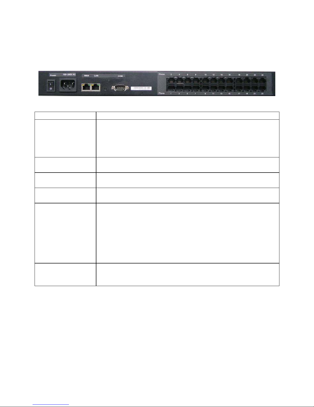
1-4 Rear Panel: LED Indicators
WellGate 2424s
Figure 1-4 rear panel for FXS
Item
Description
Phone1 - Phone24
The status LED for FXS port 1-24, this w ill lig ht up a mber
orange when the connected phone’s handset is lifte d, or
when the connected ph one is engaged in a conversation.
It w
ill flash amber oran ge w hen there is a n inc oming ca ll.
(WellGate 2424s only)
LAN
10/100 Base-T RJ-45 socket for LA N por t, con n ects to PC
for management pu r pose .
WAN
10/100 Base-T RJ-45 socket for WAN port, conn ects to
wide area network.
AC100V~240V
The power socket, inpu t AC 100V~240V, outpu t DC 12V,
6A.
Console Port
This port is for RS-232 ca ble connected , the baud rate is
115200, data bits is 8, pa r ity is none, stop bits is 1, flow
control is non e. Normally the port is used for Welltech’ s
engineer debug.
Notice: if you want to use it, just could use command
“ifaddr –print” (to display IP address of WAN and LAN port
on screen) or “passwd” (to change password), other
commands are not yet available.
Reset Button
Press and hold over 5 seconds to reload factory default
setting, th is will erase all e xisting settings c onfigured on
this gateway.
Page 7
7
1-5 QUICK SETUP
Note:
Please use Windows XP IE 6.0 web browser or above version to
configure FXO gateway webpage setting. Welltech products don’t
support other Web Browser such as FireFox to configure.
Login :
Setp1:
Setup the administrative PC’s IP address to be same as WellGate
2424s and connect the Ethernet cable into WAN or LAN port. Start IE6.0 (or
later version ) to navigate WellGate 2424s web management system by typing
the default URL which is http://192.168.123.123
(through LAN port) or
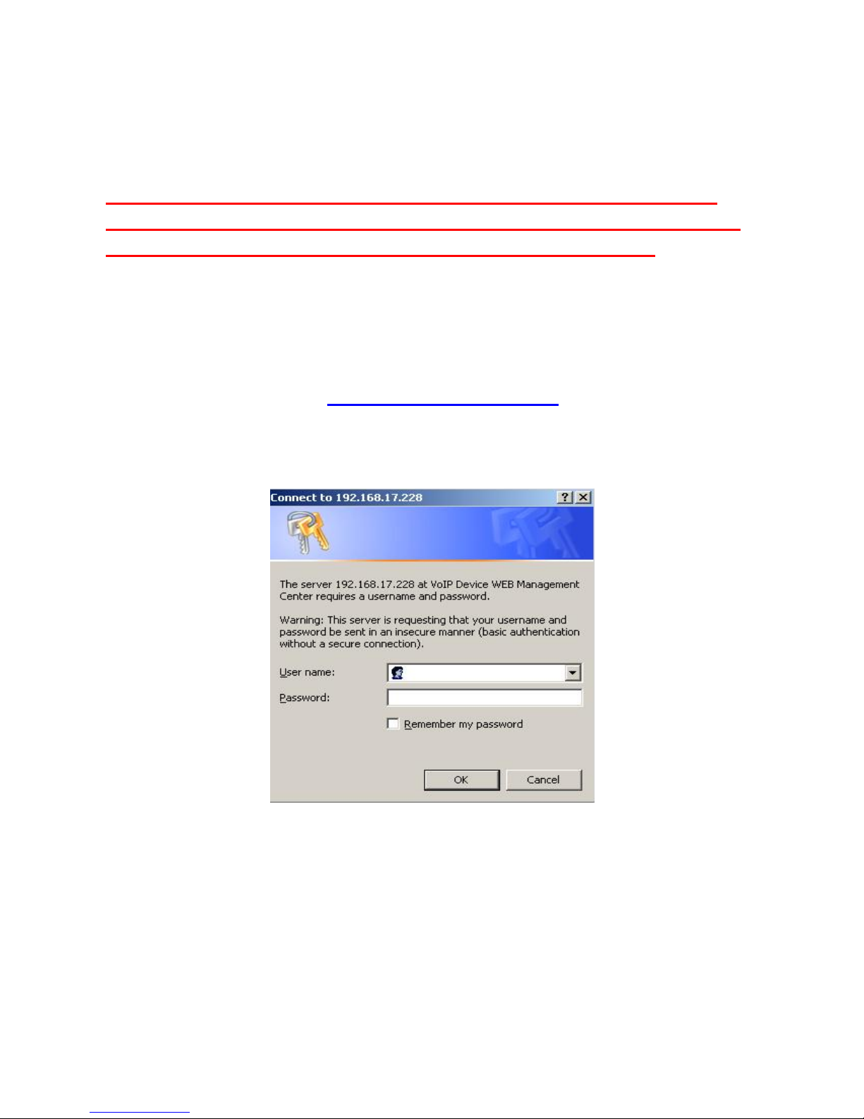
http://10.1.1.3 (through WAN port). The screen will display User Name
and Password (the default user id is root a nd user password i s root). (See
figure 1-5-1 web access)
Fi gure 1-5-1 web access
Step 2: After login, the screen shows the Home page of WellGate 2424s. (See
figure 1-5-2 Network configure-1)
Page 8

8
Figure 1-5-2 Network configure-1
Change Default IP Network:
Step 3: After successfully logon to the system, we need to change the
network con figura tion. Click Device Setting > Network to setup the service
network interface (WAN) parameters. Enter the deserved IP addres s, netmask
and default gateway or selected to “DHCP” or “PPPOE”. Apply the change by
clicking Apply button as fig (See Figure 1-5-3 Network configure-2).
Note: I f Gateway WAN port are setting in the 10.x.x.x segment, please make
sure that you also change the LAN port to other segment such as 19 2.1 68.x.x
Figure 1-5-3 Network configure-2
Page 9
9
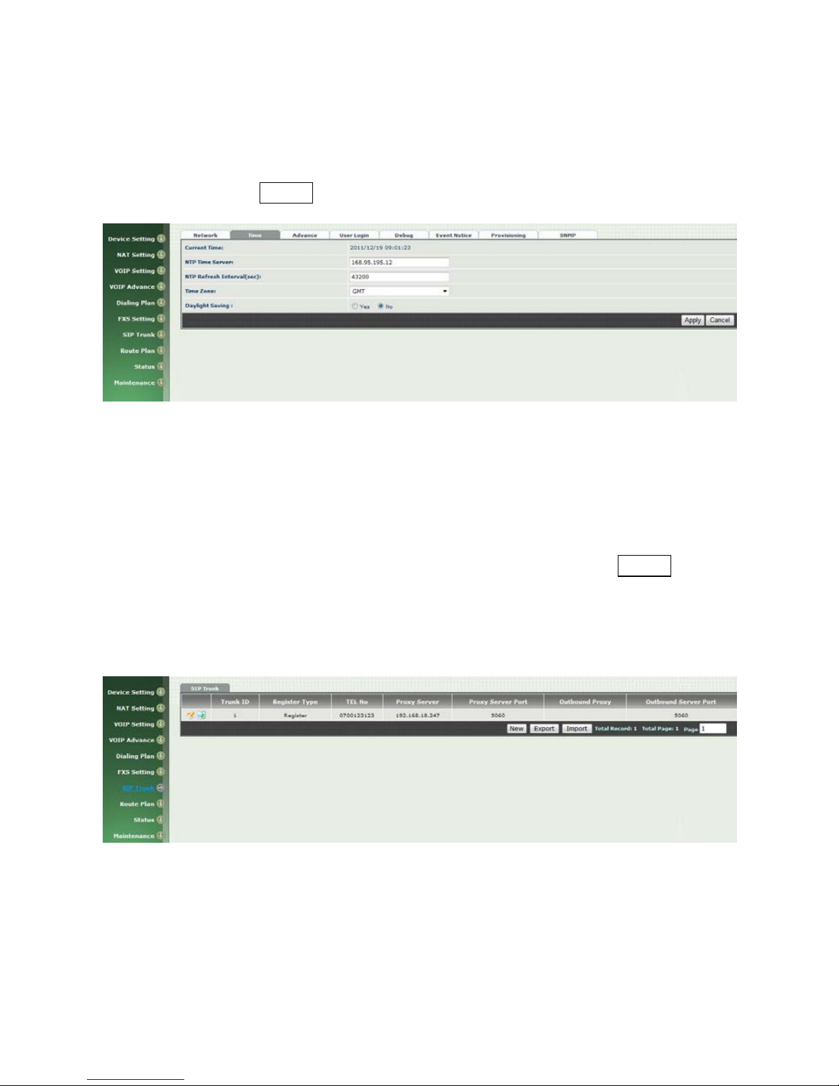
Change Defa ult Time setting:
Step 4: When re-logon to the new IP address, the next is to setup the syste m
time zone. Click Device Setting > Time to setup the system . Enter the
current SNTP server, time zone an d daylight saving parameters. Apply the
change by clicking Apply button. (See figure 1-5-4 Time setting)
Figure 1-5-4 Time setting
Modify SIP Account Parameter:
Step 5: The next step is to add a SIP trunk for VOIP calling. For WellGate
2424O, it is nece ssary for VOI P calling while WellGate 2424S is optional. Click
SIP trunk and new to create the required sip trunk. Enter the tru nk ID to 1
and input those SIP para m eters. Apply the cha nge by clicking Apply button.
(See Figure 1-5-5 SIP Trunk).
Note: please don’t delet e sip tru nk, ev en it is un less at all, be caus e it ha ve to
be used with Route plan.
Figure 1-5-5 SIP Trunk
Modify FXS SIP Se t tings: (WellGate 2424s only)
Step 6: Set the SIP proxy server for FXS calling. For WellGate 2424s, the all
FXS ports are using the same SIP proxy setting. If you need use different SIP
proxy serv er, please use SIP trunk instead. Click FXS Settings > SIP Proxy to
Page 10

10
set the dedicate FXS SIP proxy server. (See Figure 1-5-6 SIP Proxy)
Figure 1-5-6 SI P Proxy
Step 7: Setup each FXS line’s parameters by clicking the line ID from FXS
settings > FXS Line. Modify the SIP register in formation an d a p ply it. ( See
Figure 1-5-7 SIP Proxy )
Figure 1-5-7 SIP Proxy
Soft Reset WellGate 2424s:
Step 8: After modify basic setting. It is required to reset WellGate 2424s.
Click Maintenance > Maintenance > Soft-Reset or Reboot to take ef fect.
Apply the change by clicking Apply button. (See Figure 1-5-8 Quick -Reset)
Page 11

11
Figure 1-5-8 Quick-Reset
Check WellGate 2424s Registered Status:
Step 9: After soft-reset or reboot.
>Click Status > SIP Trunk Status to check whether registered or not. (See
Figure 1-5-9 SIP Trunk States )
Figure 1-5-9 SIP Trunk Sta tes
>Click line status to check whether registered or not. (Figure 1-5-10 SIP
Trunk States)
Figure 1-5-10 SIP Trunk States
Page 12

12
Through the above settings, the WellGate 2424s should a b le to do the
following:
For FXS (WG2424S):
1. The user can pick up the handset and hear dial tone. C all out and talk.
2. For VOIP incoming call to a dedicate FXS n umber, the dialed ph one will ring
and can answer to talk.
Page 13

13
CH2 Device Settings
From this settin g category, all devices related par ameters can be found here.
2-1 Network Configuration
> Network
Figure 2-1 network setting
Parameter Descript ion:
WAN Settin g:
Net work Type: support “Fixed IP”;”DHCP”;”PPPOE”
I P A ddress: IP address
Def aul t Gateway: Default gateway
DHCP Tag (option 6 0): input Vendor class identifier or not.
DH CP Ta g (option 61): input Client identifier or not.
DNS Server1: Primary DNS Server IP network
DNS Server2: Secondary DNS Server IP network
VO I P VL AN: Enable VOIP VLAN or not. When enable VOIP VLAN, the
WAN port can be only accessed by VLAN. If it is r equi red t o man age th e
WellGate 2424s, Administrator can use LAN port instead.
VOIP VLAN ID(2-4096): VLAN ID Used
Note: the default WAN IP address is 10.1.1.3.
Page 14

14
LAN Setting:
Management mode: This LAN port is used for managemen t pu r pos e,
not used for r eg is te r or r outing.
NAT mode: DHCP function on the LA N port. The LAN ports will function
as a DHCP server, network devices connected to them will be issu ed with
IP addresses. (On the lift item will add a NAT setting, the information
please refer NAT setting)
IP Address
: IP address (please set to 192. 168.x.x if your WAN port is
using 10.x.x.x IP segment).
Netmask: IP ne twork mask
Bridge mode: At this mode, both WA N and LAN ports are c onfigured to
Switch/Hub f eatures. LAN port access to WAN por t d irectly .
Note: default LAN IP address is 192.168.123.123
DDNS (DynDNS) Setting:
DDNS (DynDNS): enable or disable dynamic DNS feature.
Domain Name: input your Domain Name
User Name: input your user name
Password: input your password
Page 15

15
2-2 Device Time Setting
WellGate 2424s support SNTP with time zone and daylight saving.
Device Setting > Time
Figure 2-2 Time setting
Parameter Description:
Now: Current Time (display only)
NTP Time Server: SNTP time server
NTP Refresh Interval(sec): The frequen c y to sy nc NTP server in
seconds
Time Zone: The time-zone WellGate 2424s is located.
Standard: Use a predefin ed s tandard time zone
Customize: Use a user defined time zone
Da ylight Savi ng: Auto adjust daylight saving timer or not
Daylight Bias: The offs et added to th e Bias when the time zone is in
daylight saving time
Daylight Start: The date that a time zone enters daylight time
Month: 01 to 12
Week Day: Sunday to Saturday
Apply Week (Day:01 to 05, Spec if ies the occurrence of day in th e
month; 01 = First occurrence of day, 02 = Second occurrence of
day, ...and 05 = Last occurrence of day)
Hour: 00 to 23
Sta ndard Start: The date that a time zon e enters day lig ht time
Month: 01 to 12
Week Day: Sunday to Saturday
Apply Week (Day:01 to 05, Spec if ies the occurrence of day in th e
month; 01 = First occurrence of day, 02 = Second occurrence of
day, ...and 05 = Last occurren c e of day)
Hour: 00 to 23
Page 16
16
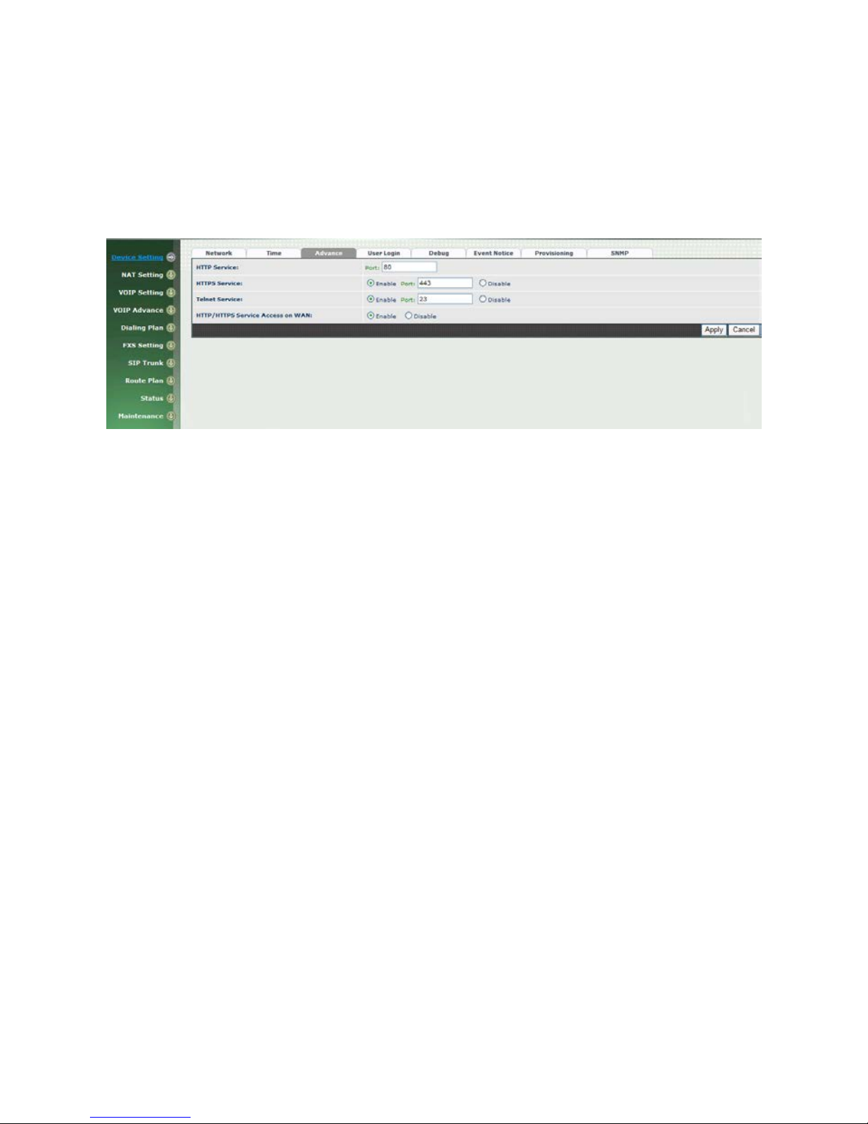
2-3 Device Advance Setting
> Advance
Figure 2-3 Advance setting
Parameter Description:
HTTP Service: The Administrator Web service port (the default is 80)
HTTPS Service: The https web service port (the default is 443)
Telnet Service: The telnet service port (the default is 23)
HTTP/HTTPS Service access on WAN: When clic k the disable option;
The WEB service will be rej ected on W AN port, so please be c areful w ith
this function. If you wanted to en a ble WAN port again, you need to
access this device from its LAN port to c onnect to WEB pages and enable
WAN por t.
Page 17
17
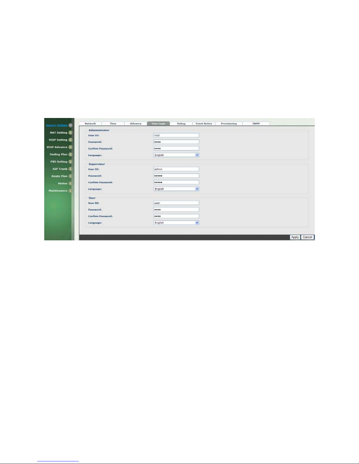
2-4 User Login Setting
Three level of user s can be used, administrator, supervisor, user. Each level of
users will have different predefined acc es s level.
>User Login
Figure 2-4 user login setting
Parameter Description:
Administrator: The administrator level user which has full access of
WellGate 2424s.
Supervisor: The supervisor level user which has limited administrative
access right.
User: The user access right which only allows to setting some user
related features.
User ID: Login User ID
Password: Login Password
Confirm Passw ord: Confirm new password again
Language: The web page language used when the a ccount login. To add
a customized local language , please contact Welltech.
Page 18
18
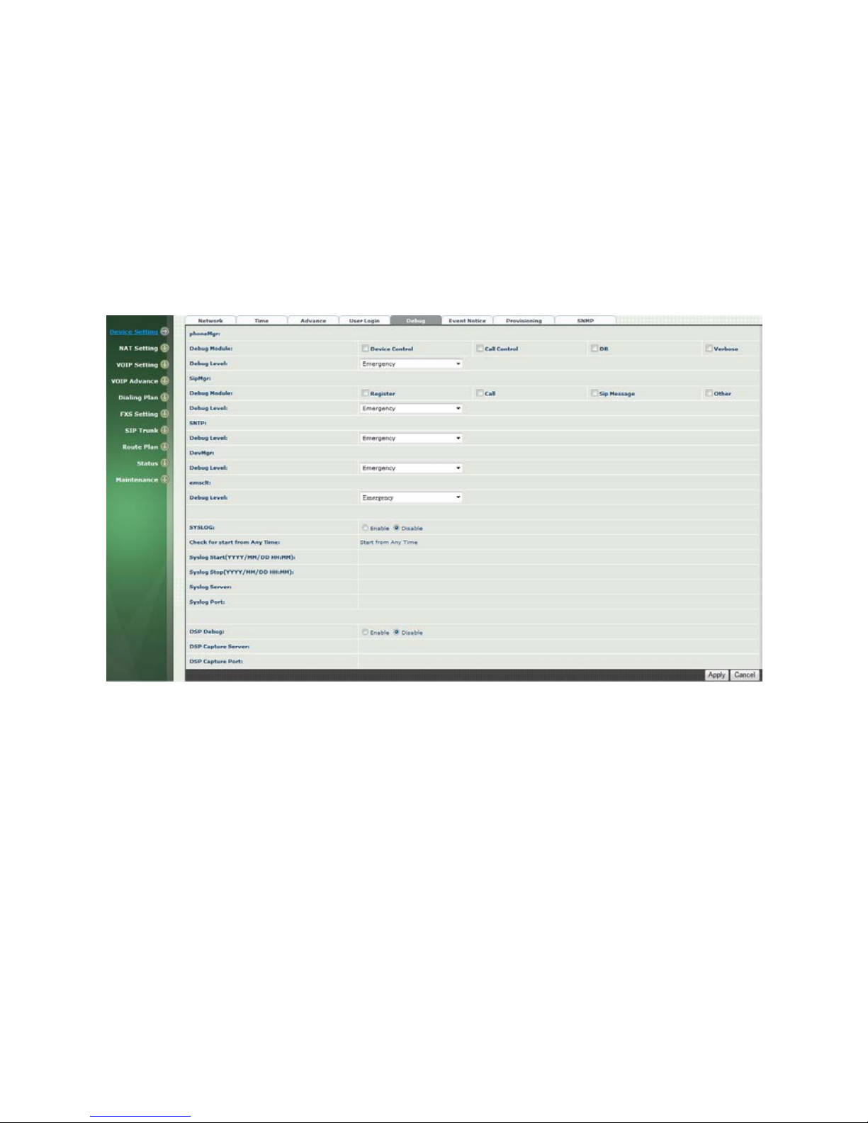
2-5 Debug Settings
WellGate 2424s provides the real time debug to syslog or through telnet interface. It
generates the debug information based on debug level and modules. Since the
generating debug will consume system resource, it is recommended to turn on only for
necessary and under Welltech FAE’s instruction.
Debug
Figure 2-5 Debug setting
Parameter Description:
SYSLOG: En able or disab le to send sy stem infor mation to SYSLOGD
server or not
Check for start from Any Time: Always Send: Always send syslog
or only during a specified time range.
Syslog Start (YYYY/MM/DD HH:MM): Always Send: Always
send syslog or only du r in g a spec if ied time range.
Syslog Stop (YYYY/MM/DD HH:MM): The syslog stop sen ding
time.
Sy sl og Se rv er: Syslog server IP address
Syslog Port: syslog server service port (default is 514)
DSP De bug: Enable or disable to send DSP information to captur e log
DSP Capture server: Syslog capture server IP address
DSP Capture port: syslog capture server service port (defau lt is 50000)
Page 19
19
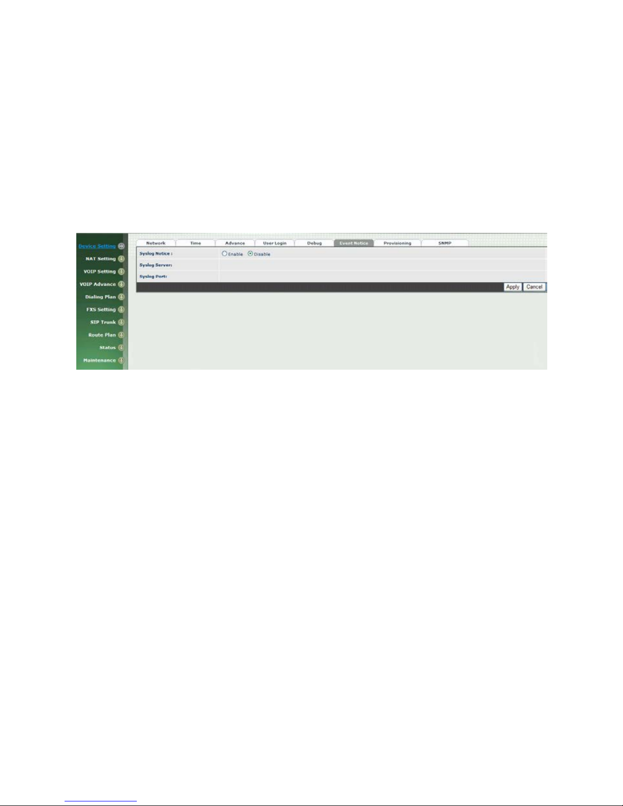
2-6 Event Notice
WellGate 2424s can send Syslog Ev ent Notice when it had th e following cases:
1. Register Failure or re-registered
2. FXO is plug or unplug
3. Ethernet reconnected
4. System started
Figure 2-6 Event notice setting
SYSLOG: Enable or disable to send system event to SYSLOG
server or not
Sy sl og Se rv er: Syslog server IP address
Syslog Port: syslog server service port (default is 514)
Page 20
20
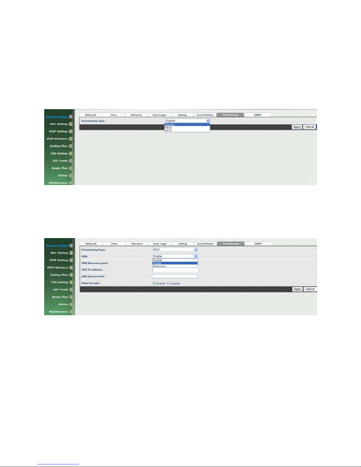
2-7 Auto Provisioning
The WellGate 2424s can be provisioned by WellEMS 9510 for large deploym ent.
Please contac t Welltech for availabilities.
>Provisioning
Figure 2-7-1 Provisioning
Select 9510:
Figure 2-7-2 Provisioning type of 9510
Parameter Description:
(This function is not available yet for WellEMS 9510)
EMS: Enable auto pr ovisioning s ervice by WellEMS 9510 or not.
Enable: Enable the service and use manual conf igu r ed EMS server
parameters.
Disable: Disa ble the auto provisioning service.
Discovery: To automatica lly discov e r the EMS serve r or not. By
using this mode, WellEMS 9510 need to be the same IP netw or k in
order to make the IP broadcasting work.
EMS Discovery Port: WellEMS 9510 service auto discovery
Page 21

21
broadcasting port (defa ult is 61005).
EMS summary refresh interval: How long the WellGate 2424s
will report its su mmary status to WellEMS 9510 in seconds.
EM S I P a ddr ess: The WellEMS 9510 server IP address
EMS Se rver Port: The WellEMS 9510 Server port
Data Encrypt:
Disable: disable encryption function.
Welltech encryption: Enable Welltech proprietary encryption for S IP
signaling and R TP. It is requ ired a Welltech SIP proxy server (WS6500 or
SIPPBX 62 00) to work with this feature. When enable it, you c an hide
your VOI P traffic from ISP’s monitor.
External encryption: for custom encryption, it is valid now, if you want
add the function to mach your proxy, please con ta ct with Welltech’s
sales.
Select Http:
This feature is for feature usage only.
Figure 2-7-3 Provisioning type of Http
H t t p c onfig URL: internal used only
Refresh interval(minute): interval to check whether have a new
configuration/firmware or not in minutes
User ID: specify the login id for http authentication
Password: specify the password for http authentication
Page 22

22
2-8 SNMP
Figure 2-8 SNMP
SNMP Agent:
SNMP Agent: Enable SNMP or not.
Read Only Community Name: The community name to read
through SNMP protocol
Read Write Community Name: The community name to read and
write through SNMP protocol.
SNMP Agent Acce ss on WAN: Enable SNMP to be accessed
through WAN port or not.
Trusted Peer:
Type:
Any Address: Any address can retrieve the SNMP
information.
Specify an I P Address: Only the IP address listed can
retrieve the SNMP information . Normally, it will be the SNMP
manger IP addres s .
Specify a Su bnet: Only the network spec ified can retrieve
the SNMP information.
I P a ddr e ss: The IP address for a trusted peer
Subnet Mask: The network mask for a trusted peer
SNMP Trap:
SNMP Trap: Enable SNMP tra p or not
Destination: The I P address for SNMP manager to receiv e the SNMP
trap
Community: The communicate name for sending the SNMP trap
Page 23

23
CH3 NAT Setting
The WellGate 2424s can support N AT, 2 ethernet leg ( gw ) or br idge mode.
Here are the settings for NAT related service.
3-1 DHCP Ser. (DHCP server)
Figure 3-1 DHCP server
DH CP Server: Enable DHCP server or not.
Client Range Start IP: specify DHCP client lease start IP
Client Range End IP: specify DHCP client lease end IP
Def aul t Gateway: specify the default gateway
Submask: specify the submask.
DNS Server 1: specify the DNS server
DNS Server 2: specify the DNS server
Page 24

24
3-2 UPNP (universal plug and play server)
Figure 3-2 UPnP
UPN P IG D: Enable UPNP server or not.
3-3 Bandwidth (Bandwidth Control)
By using bandwidth control feature, the user can manage the traffic based on
their needs.
Figure 3-3-1 Bandwidth control
Bandwidth Control:
Ba n dwidth Contr ol: enable bandwidth control or not.
Download Bandwidth: specify total ban dwidth for dow nload (unit:
kbps). 0 indicates no limitation.
Upload Bandwidth: specify total bandwidth for upload (unit: kbps).
0 indicates no limitation.
Maximum Bandw idth a nd Reserved Bandwidth:
Se tu p M e t hod: bandwidth control m ethod, percentage or specify
Page 25

25
the required bandwidth
perc entage : total bandw idth
priority 1: highest priority percentage
priority 2: Normal priority per c e ntage
priority 3: low priority percentage
Figure 3-3-2 Bandwidth control
specific :
priority 1 – Download: highest priority download bandwidth
priority 2 – Download: normal priority download bandwidth
priority 3 – Download: low priority download bandwidth
priority 1 – Upload: highest priority upload bandwidth
priority 2 – Upload: normal priority upload bandwidth
priority 3 – Upload: low priority upload bandwidth
Figure 3-3-3 Edit control list
In order to set whic h target is belonged to which p r iority, the following is the
setting meth od for target’s priority.
Page 26

26
IP Target
Figure 3-3-4 IP Target 1
Figure 3-3-5 IP Target 2
Priority: Priority value for the target
Type: The target type is set to IP
Configure Type: unique IP or a range of IP address
Unique:
IP Address: the IP address to be set
IP Range:
Start IP: The starting IP for a range
End IP: The stopping IP for a range
Port Target
Figure 3-3-6 Port Target
Priority: Priority valu e for the target
Page 27

27
Type: The target type is set to port number
Conf igure Type: unique port number or a range of port number
Unique:
Port: the port number to be added
Protocol: protocol for the port
Port Range:
Start port: the starting port number
End port: the stop port number
Protocol: protocol for the port r a nge
Application Target
Figure 3-3-7 Application Target
Priority: Priority valu e for the target
Type: Application
Application: the list for the application
DSCP target
Figure 3-3-8 DSCP Target
Priority: Priority value f or the target
Type: DSCP value
DSCP: The DSCP will be mapped to the prior ity
Page 28

28
The WellGate 2424s support fir ewall features as below.
3-4 URL Filter
Figure 3-4 URL Filter
URL Filter: the specified url will be blocked
3-5 IP Filter
Figure 3-5 IP Filter
IP Filter: The specified IP address to be blocked
Local IP addre ss: The LAN side IP address to be forwarded
Protocol: TCP, UDP or both are used for port forward
Page 29

29
3-6 MAC Filter
Figure 3-6 MAC Filter
MAC Filter: The MAC address to be blocked
3-7 APP Filter
Figure 3-7 App Filter
APP Filter: application to be blocked
Page 30

30
3-8 Port Filter
Figure 3-8 Port Filter
Port Filter: enable port Filter or not.
Port Range: Starting and stopping port t o be forward. If you are
using only 1 port, please set the starting equal to stopping port.
Protocol: TCP, UDP or both are us ed for port blocked.
3-9 Port Fwd
The WellGate 2424s support port for ward feature as below
Figure 3-9 Port Fwd
P ort F wd: enable port forward feature or not
Port Range: Starting and stopping port t o be forward. If you are
using only 1 port, please set the sta r ting equal to stop ping port.
Protocol: TCP, UDP or both are used for port forward
L oc a l IP address: The LAN side IP address to be forwarded
Local Port: The LAN side port to be forw arded. I f you are usin g the
port range, this port indicates the starting port.
Page 31

31
VOIP Parameters Setting
SIP Parameters:
CH4 VOIP Setting
4-1 SIP
Figure 4-1 SIP setting
Parameter Description:
Session Tim er: Enable session tim er or not (RFC 4028)
Session Expires (sec): This is th e s etting of initial ses s ion timer
expires time according to RFC4028 - Session T im er s in the Session
Initiation Protocol.
Min SE (sec): The minimum session timer allow ed when receiving a
call with sess ion timer value according to RFC 4028.
PRACK: Enable provisioning ACK or not ( RFC 3262)
None: Disable PARCK
Supported: When select this mode, 100rel will be added to the
support list. I t indic at es WellGate 2424s can support the PRACK but
not mandatory.
Require: PRA CK is mandatory required.
SIP Local Port: The SIP local service port (default is 8080)
SIP Qos Type: Quality of Ser vice Type for SIP signaling
- None: Not using QOS Tag and not enables QOS.
- DiffServ: Differentiated Services Value. Input DSCP value 0-63 for
DSCP
- TOS: Type of Service which include IP precedence value and TOS.
Acce pt Proxy Only : Only accept the c all coming from the SIP
proxy.Not accept p eer to peer call at this mode.
Page 32

32
4-2 Audio
Figure 4-2 Audio setting
Codec 1~5: The preferred codec priority
G .711u P a y load Size: G.711 u-Law payload size
G .711a P ayload Size: G.711 A-law pay loa d s ize
G .729 P a y load Size: G.729A payload size
G .723. 1 P ayload Size: G.723.1 payload size
Bi t R ate : G.723.1 bit rate used
5.3K bit rate is used
6.3K bit rat e is used
Codec Priority: Selection order to match the r e m ote SDP for codec
selection.
Local SDP Order: Use local SDP order to match codec
Remote SDP Order: Use Remote SDP order to match codec
DTMF Relay:
In-Band DTMF: use inband DTMF instead of out of ba nd.
RFC 2833(fall back to SIP-INFO): Use RFC 2833 if the SDP
negotiation c ould be done. Or use SIP INFO for DTMF relay.
SIP INFO: Use SIP-INFO DTMF relay
RFC 2833(fall back to Inban d): Use RFC 2833 if the SDP
negotiation c ould be done. Or use inband DTMF transmission.
Page 33

33
Silence Suppression:
Enable: Start the voice activ ity (silence) det ec tion when detect
silence for 60 seconds, it will hang up the call (For FXO use)
Disable: Send silence packet as normal voice packet (no silence
detection)
R TP Ba sic P ort: The RTP starting port. Each channe l will be add
additional 10. F or example, the R TP basic port is 16384, th us call 1 will
use 16384 while call 2 will use 16394 etc.
R TP Q os Type: IP QoS tag for RTP s tream
DiffServ: The differentiat ed s er v ic e Q oS ta g will be used.
Input DSCP value 0-63 for DSCP.
TOS: Ty pe of Service which include IP pr ec edence value
and TOS.
Page 34

34
4-3 Tone
The setting page is used to setup the tone to be generated or detected. The
detected tone is the Disconnect 1 & 2 (for FXO use) and the others are for
generating (when FXS received the “bye” from IP side or waiting time
out by analog phon e which keeps ha ndset pick up, it wi ll send busy
tone to analog phone). The disconnect tone is very important for PSTN
status supervision.
Figure 4-3 To ne setting
Please use C ountry Template t o select the c ountry prof ile which will b e applied.
Click Use to load those country tone parameters to system and change if
necessary. For those countries are not showed in the list, please select a
closed c ountry an d edit to match y our countr y . Y ou can sen d an email with the
tone definition to W elltech if you would like to put your cou ntry into the list.
Page 35

35
4-4 NAT Traversal
The WellGate 2424s suppor t the following NAT trave r s al methods
Figure 4-4 NAT Traversal
NAT Traversal:
Disable: Disable NAT traversal features
STUN (Type 1,2): Enable STUN for NAT tr aversal. Since
STUN can be used only f or type 1 and type 2 NA T serv er, it is
recommende d to use this option. When STUN client detect
the used NAT is type 3 NAT, it will stop the STU N feature.
STUN Server: STUN Server IP address
STUN (All): No matter which NAT type server are used,
STUN is always to be used for NAT traversal.
STUN Server: STUN Server IP address
UPNP: Enable UPnP client for NAT tr aversal. Please note that
the IP sharing bo x need support uPnP feature.
Behind NAT: Use DMZ for NAT traversal
IP Sharing Address: public IP sharing address. You
need to specify the port mapp ing or DMZ for all
required port.
Page 36

36
CH5 VOIP Advance
5-1 SIP
Figure 5-1 SIP
Parameter Description:
SIP Hold Type: SIP on hold message sending method.
- Send Only: Set the SDP media to sendonly when send an on-hold
SIP message.
- 0.0.0.0: Set the SDP connection to 0.0.0.0 when send an on-hold
SIP message.
- Inactive: Set the SDP media to inactive when send an on-hold SIP
message.
SIP Compact Form: Enable SIP compact form or not. When en able
this featur e, the connected SIP proxy is requ ired to support compac t
form.
Session Refresher: Who will send dialog keep alive message
(re-invite or upd a te).
UAC: User Agent Client will do the r e fresh (defa ult setting)
UAS: User Agent Server will do the refresh
SIP T1 (msec): T1 determines several timers as defined in
RFC3261. For exa m ple, when an unreliable trans port protocol is
used, a Client Invite transaction retransmits req uests at an interval
that start at T1 seconds and doubles after every retransmission. A
Client General transa ction retransmits reques ts at an interv a l that
starts at T1 and doubles until it reaches T2. (Default Value: 500ms)
**
Page 37

37
SIP T2 (msec): Determines the maximum re transmission interval
as defined in RFC3261. For example, when an unreliable trans port
protocol is used, genera l r eq uests are retransmitted at a n interval
which starts at T1 and doubles until reaches T2 . If a provisiona l
response is rec eived, retra nsmission continu e but at an interv al of T2.
(Default Value: 4000ms) **
SIP T4 (msec): T4 represen ts the amount of time the network
takes to clear message between client and server transactions as
defined in RFC3261. For example, when work in g with an unreliable
transport p rotocol, T4 determines the time that UAS waits after
receiving an AC K m es s a ge an d bef or e term inating the trans a c tion .
(Default Value: 5000) **
Invite Linger Timer: After sending an ACK for an INVITE final
response, a client cannot be sure that the serv er has received the
ACK message. Th e client should be able t o retransmit the ACK upon
receiving retr a nsmissions of the final resp onse for this timer. T his
timer is also u sed when a 2xx respon se is sent for an incomin g Invite.
In this case, the ACK is not part of the Invite transaction.
General Linger Timer: After a UAS sends a final response, the UAS
cannot be sure tha t th e c lien t has received the respon s e m es s a ge.
The UAS should be able to retransmit the response upon receiving
retransmiss ions of the request based on this tim er .
Ca nc el General No Response Ti me (msec): When sending a
CANCEL request on a General transaction, the User Agent waits
cancel General No Response Timer millisecond s be fore timeout
termination if there is no response for the cancelled
transaction(Default Value: 10000ms).**
General Request Timeout Timer (msec): After sending a
General reques t, th e U s er A gent waits for a final response general
Request Timeout Timer milliseconds be fore timeout termination (in
this time the User Agent retransmits the requ est every T1,
2*T1,…T2,…milliseconds)**
Ca nc el Invite No Response Time r (msec): When sending a
CANCEL request on a n Invite request, the User Agent waits this
timer before time out termination if there is no response for the
cancelled transaction.
Provisional Timer (msec): The provisionalTimer is set when
receiving a pr ovisional res p onse on an INVITE transaction. The
transac tion will stop retransmissions of the IN VITE request and will
wait for a final response until the provisionTimer expires . If you set
the provision T imer to 0 , no tim er is s et. Th e INVI TE tr an sa ction will
wait indef initely for the final response.
First Response Timer (msec): When sending a request out, the
User Agent waits this timer for any r esponse receiv ed from UAS. If
timer is expired and n o any SIP mess age is received, t he User Agent
Page 38

38
will think th e request is failed. The default is 5 s e c onds.
MWI Subscript Expires (sec): Y ou can Enable or Disable the MWI
subscribe. The default is 600 sec. If a new voice mail is arrived, the
stutter tone will be used inste a d of regular dial tone. This feature is
dedicate to FXS only.
L ine Congesti on Code: when callee's end system was contacted
successfully but the callee is busy an d does n ot wish to ta ke the call
at this time, the system wills response the code, default is 600.
(FXO use)
SIP-Info Flash Mode: when you enable the feature, sys tem will
make flash key to send SIP message by sip-info.
5-2 Audio
The setting pa ge in c ludes the device related audio settings.
Figure 5-2 Audio setting
RFC 2833 Pa y load Type: 96 or 101. It is recommended to use 101.
DTMF Send On Time(msec): When generate DTMF, the DTMF on
time will be send (defau lt value is 70 ms)
DTMF Send Off Time(msec): When gen erate DTMF, the DTMF off
time will be send (defau lt value is 70 ms)
DTMF Detect Min on Time (msec): The minimum D TMF on time will
be processed as a regu lar DT MF even t. Smaller than it will be ignored.
The default v a lue is 60ms.
DTMF Detect Min off Time (msec): T he minimu m DTMF of f time for
the same DTMF value. Smaller than it and the new DT MF digit is the
same as previous on e w ill be h a ndled as 1 digit only.
Page 39

39
DTMF Relay Volume: The DTMF relay volume
T. 38 F a x Vol ume : The T.38 fax relay volume
T.38 Redundant Depth: The T.38 redundant packet depth. It could 0
(no redundant), 1 or 2. It is recommended to set to 2.
T. 38 ECM: The t.38 error correction mode. Default value is ON.
Min Jitter Buffer (msec): The minimum delay tim e of Jitter buffer.
Max J itter Buffer (msec): The Maximum delay time of Jitter buf fer.
Max Echo Tail Length (G.168): Enable the echo cancellation feature.
The defau lt s e tting is “128ms”.
J i tte r O pt. Factor: Jitter buffer dynamic factor for optimize. Please
set to 7 unless under Welltech’s instruction to ch a nge.
Impedance: selected analog phone’s impedance. (for FXS port use)
Page 40

40
5-3 Ring
The ring cadence, voltage and frequency f or th e phone
Figure 5-3 Ring setting
Frequency (10~70HZ): Specify the ringing frequency v alu e
(default is 20HZ)
Ring on (0~8000 ms): Specify the ringing on value (default
is 1000msec)
Ring off (0~8000ms): Specify the ringing off value (default
is 2000msec)
Ring level (10~95volt): Specify the ringing level ( d ef au lt is
94 volt)
Page 41

41
CH6 Dialing Plan
6-1 General
Figure 6-1 General setting
F irst Digit Time Out:
Specify the duration of dial waiting when the
receiver is off hook. The r ange is 1~60 sec.
Inter Di gi t Ti me O ut: Specify the interval of input digits, if the
interval is over the setting, the sys te m will end the dial an d s e nd out
the DTMF. The limitat ion
range is 1~10sec.
End of Digit: The assigned key will be tread as end of dial.
Retrieve Number: it will forced to get back line, if used WellGate
2424s make tr a nsfer to other devices bu t th e devices no answer and
into voice ma il,
You can press the code forced to get back line. Default is “*#”.
Page 42

42
6-2 Dialing Rule
Figure 6-2 Dialing Rule setting
Dialing rule is used to speed u p the dialing procedure. Some user don ’t like to
use the end of dialing digit such as “#”, the administra tor ca n us e dialin g rule
instead. The longest pref ix will be matched first.
Dialed Prefix: The prefix to be matched
Max Digits: The digits will be receiv ed based on the Dialed P refix.
The followin g is an example for dia ling rule:
Mobile call is star ted with 09 an d it is 10 digits
Long distance call is starte d with 0 and it is 10 dig its
International ca ll is start ed with 00 and its max digit sh ould be less than 32
The others ar e loc a l call and 8 digits
Emergency call is s tarted with 1 and 3 digits
The Dialing rule can be set as follows:
Prefix, max digits
09, 10
0, 10
00, 15
1, 3
2, 8
3, 8
4, 8
5, 8
6, 8
7, 8
8, 8
9, 8
Page 43

43
6-3 Digit Manipulation
The Digit Man ipulation will be pr ocessed based on prefix and DM group after
the DNIS is determined.
Figure 6-3 Digit Manipulatio n setting
DM Group: Different DM group hav e dif ferent case to be used.
FXS: This DM group is used for FXS dialing out.
VOIP: This DM group is used for VOIP incoming call. After the
DNIS is collect ed in 2 sta ge dialin g or 1 sta ge dia lin g DNIS, this
DM group will be proc es sed before enter the routing procedure.
1-4: These DM groups are used for backup routing purpose.
When a backup routing is used, the administrator can select a
DM group to be processed before start the backup route.
Matched Prefix: The prefix to be matched for D M. Th e longest prefix
will be matched first.
Matched Length: S et to 0 for ignorin g the length. The other 1-32 ar e
the length to be matched a s a condition.
Sta rt P os: The start position to be replaced.
St op P os: The stop position to be replaced.
Replace Value: The value to replace.
Example of Digit Manipulation Settings:
Prefix
Len
Start
Pos
Stop
Pos
Replace
Value
Test DNIS
Result DNIS
886
0 0 0
002
8862123456
0028862123456
886
12 0 0
002
8862123456
8862123456
886
0 2 5
002
8862123456
8800223456
886
0
30
30
002
8862123456
8862123456002
886
0 1 6 8862123456
83456
Page 44

44
6-4 Phone Book
Phone Book is used for peer to peer c a ll.
Figure 6-4 Phone Book setting
Name: This field supports called number only. If you enter words or
text here, it will routes to proxy server automatically.
Tel No: Enter c alled number and I P address. Please follow this sample of
picture, as the format of “number@uri:port”. (default port is 5060)
Export: To backup the phone book records.
Import: To reload setting of phon e b ook.
Page 45

45
CH7 FXS Setting
The F XS line setting includes each line number and SI P proxy settings.
Figure 7-0 FXS setting
Line ID: FXS line (T1 to T24)
State: The line is active or not
TEL No: The telephone number
Hotline TEL:
If hot line is se t, this field show s the hot line number.
Export: backup all lines setting.
Import: reload all line setting.
Page 46

46
7-1 FXS lin e
Figure 7-1 FXS setting
User ID: FXS Line number (T1 to T24)
User Type: The line type, FXO or FXS
Line State: Set to activ e if y ou w ou ld lik e to us e this lin e. O ther wis e,
set to Inactive.
Forward reason:
Unconditional forward: forward the call all the time
Busy forward: Forward the call when phone is busy.
No answer for ward: forward the call when the call does not
answered a fter no answer timeout.
Forward TEL: The forward telephone number for the selected
reason
No answer timeout: sec The no answer timeou t will be used (default
is 120 sec)
Call waiting: Enable call waiting or not. When disable call waiting
features, the second incoming call will be rejec ted.
Reject Anonymous Call: Reject the anon y mous inc oming call or n ot
H ot line: Enable to disable hot line feature
Hot line TEL: The number to be dialed automatically after the user
pickup the phone.
Polarity Reversal generation: Enable Polarity Reversal for FXS as
billing signal or not. When a FXS calls to VOIP and answered by the
VOIP, WellGate 2424s will generate reverse signal to FXS as a billing
Page 47

47
start. When VOIP side disconnect first, WellGate 2424s will reverse
back as a billing stop signal
.
Current Drop generation: Enable current drop (0 voltage) when
VOIP is disconnected or not.
Input(Encode)Gain: Adjust the v olume from FXS to VOIP (default is
0 db)
Output(Decode)Gain: Adjust the volume from VOIP to FXS (default
is 0 db)
FAX Relay: Enable T.38 Fax Relay or not
Voice mail subscription: enable voice mail subscription (MWI) or
not.
Ca ller ID mode:
Inhibit: don’t send caller ID to analog phon e .
Transparent: send caller ID to a nalog phone.
SIP caller I D mode:
Inhibit: don’t send caller ID to VOIP SIP
Transparent: send caller ID to V OIP SIP
Register Type:
Register: register to proxy . If it is not registered to SIP proxy ,
the FXS line s till can use SIP tr unk for VOIP call.
Predefine: When it is set to predefine, WellGate 2424s will
not send register message out.
Internal: When it is set to intern al, WellGate 2424s does not
send register me ssage out, the FXS line still c an use SIP trunk
for VOIP ca ll or c all locally.
TE L No: The registrar tele phone number
User ID: The SIP user ID for register and call making
U ser Password: The SIP password for register and call making
Display Name: The SIP display n a m e
Page 48

48
7-2 SIP Proxy
The SIP proxy s erver defined here is dedicated used for FXS lines .
Figure 7-2 FXS setting
Domain: The SIP domain for register or call making
Primary proxy server: Primary SIP registrar s erver address
Primary proxy server port: Primary SIP registrar server port
number
O u tbound Proxy server: Primary outbound proxy server addres s
O utbound Proxy serv er port: Primary outbound proxy server port
number
Primary Proxy server keep Alive: using through NAT and keep the
port.
Keep Alive Time (sec): Specify of times send sip r egister message to
proxy server.
Se condary Proxy: Enabl e seconda ry proxy or no t. When enable it,
the primary and sec ondary proxy will be registered at the sa m e time.
Secondary proxy server: Secondary SIP registrar server address
Secondary proxy port: Secondary SIP registrar server port number
Secondary outbound Proxy server: Secondary outbound proxy
server address
Secondary outbound Proxy server port: Secondary outbound
proxy server port number
Register Expire: SIP register time to live
Primary Proxy server keeps Alive: using through NAT and keep the
port.
Keep Alive Time (sec): Specify of times send sip r egister message to
proxy server.
Page 49

49
7-3 Caller ID
The call ID stand for the phon e
Figure 7-3 Caller ID setting
Caller ID Mode: Caller ID mode to be used for phone (FSK
Bellcore/FSK ETSI/DTMF)
Polarity Reverse before caller ID: start polarity reverse before
send the caller ID
Dual tone before caller ID: S end dual tone before caller ID (for FSK
ETSI use only)
Caller ID present: The timing to send th e c a lle r ID
(Before fir s t r ing/after firs t r ing/after first short ring)
DTMF caller ID start digit: specify the DTMF caller ID start digit
(default is D, the range is A to D and #)
DTMF caller ID stop digit: specify the DTMF caller ID start digit
(default is C , the range is A to D and #)
Page 50

50
7-4 Others
Flash time and current drop generation time
Figure 7-4 Others setting
Min flash time(80~800msec): Specify the value of th e flash (low),
If the phone-set’s flash time is smaller than the Flash Low setting, the
flash will be ignored.
MAX flash time (80~800msec): Specify the value of the flash
(high),
if the phone-set’s flash time is larger than the Flash high
setting, the flash will be handled as hang-up.
Cur rent Dr op Times ( msec): Specify the value of the current drop
times (generate – for FXS / detect – for FXO).
Page 51

51
CH8 SIP Trunk
The administrator needs to set the SIP trunk for VOIP outgoing call
and incoming call. There are up to 16 SI P trunk can be used for whole
system.
Figure 8-0 SIP Trunk setting
Trunk ID: SIP trunk ID 1 to 16
Register Type: Register type is predefin e or r egister
TE L No: The Tel no for the SIP account
Proxy S e rv er: The SIP proxy server
Proxy S e rv er port: The SIP proxy serv er port
O u tbound Proxy: The SIP outbound proxy sever
O u tbound Serve r P ort : The SIP outbound proxy serv er port
Page 52

52
8-1 Create SIP Trunk
Figure 8-1 SIP Trunk page
Trunk ID: SIP trunk ID 1-16
Register Type: Whether this account need register or not
Register: W hen it is set to register, WellGate 2424s will send
REGISTER message to S IP proxy server for regis tration.
Predefine: When it is set to predefine, WellGate 2424s w ill NOT
send REGISTER mes s a ge out.
Domain: The SIP domain for registe r or call making
Proxy S e rv er: SIP registrar server address
Proxy S e rv er Port: SIP registrar serv er por t n umber
O u tbound Proxy Ser ver: outbound proxy server a ddres s
O u tbound Proxy server port: outbound proxy server port number
Register Expires: the default register expires for negotiation
TE L No: The registrar telephone num ber
User ID: The SIP user ID for register and call making
U ser Password: The SIP password for register and call making
Display Name: The SIP display n a m e
Reject Anonymous Call: Reject the anonymous call
O u tgoing Calle r I D : The outgoing SIP caller ID mode.
Display Name: The display name will be set according to the
following type.
None: No display name will be used
SIP display name: The display name will be the D is pla y Name
set in this SIP trunk.
SIP user ID: If the SI P user ID is se t, the SIP user ID se t in this
SIP trunk will be used and th e domain/SI P proxy will be the host
Page 53

53
part. The SIP FR OM header’s URL will be the
SIP_User_ID@ Dom a in or S IP_User_ID@SIP_Pr oxy_Server.
Keep Alive: Enable or Disable it.
Keep Alive Time (sec): Specify of times send sip register m essage to
proxy server.
Note: please don’t delet e sip tru nk, ev en it is un less at all, be caus e it ha ve to
be used with Route plan.
Page 54

54
CH9 Route Plan
The core of WellGate 2424s is the routing policy . The policy is base d on
incoming call type/target, length and pre fix to determinate the
outgoing call process. For VOIP incoming call, it can send to FXS
interface and vice versa.
For FX S interface, it could b e routed to VOIP a nd vice versa. Y ou can ignore the
routing plan if you don’t need it for FXS interface.
Figure 9-0 Route Plan page
I nc oming Call Type: Incoming call type ( VOIP or FXS)
Matched Pre f i x: matched DNIS (called number) prefix
M a tc hed Incomin g List: matched DNIS incoming interface tar g et
M a tc hed Length: matched DNIS (called number) length
O u tgoing Type: The outgoing call type (FXS or VOIP)
Export: backup route plan setting.
Import: reload route plan settin g .
Page 55

55
9-1 Create Route Plan
Click Route Plan and Click new to create a new routing policy.
Figure 9-1 Route Plan setting
I nc oming Call Type: Incoming call type
VOIP: The incoming SIP call type
FXS: The FXS extensions incoming call type
Matched Pre f i x: matched DNIS (called number) prefix
M a tc hed Incomin g List: matched DNIS incoming interface target
For VO IP incom ing call ty pe, th e inc omin g tar get w ill be
the SIP trunk ID. Only the call from the selected SIP
Trunk will be accepte d for this route.
For FXS incoming call type, the incoming target will be
the line ID ( T1 to T 24) . O nly th e call is c omin g from the
selected line will be acc epted for this route.
Matched Length: matched DNIS (c alled number) length. F or ignoring
the length, please set to 0.
No Answer Timeout: How long the hunting will continue to next
when the called target do esn’t answer.
Create Route Plan>Primary Route
O u tgoing Type: Outgoing call type (FXS or VOIP)
Page 56

56
H u nting Type: The hunting method will be us e d for this route.
Priority Ring: The call will be hunted based on the
routing list or d er one by one.
Cyclic Ring: The call will be hunted based on the cycl ic
basis. This is the r ec omm ended method.
Routing List:
The routing target list will be used for this route.
DM Group: Select DM group 1 to 4 in case it requires a DM (for
example remove the prefix) before to m a ke the call.
Create Route Plan>Backup Route
Backup Route Active: Active the backup route or not.
O u tgoing Type: The backup route outgoing ca ll type.
Hunting Type: The hunting meth od will be used for this route . Please
refer to the Pr im a r y Route.
Routing List: The backup routing target list will be used for this r oute.
Route DM Group: Select DM group 1 to 4 in case the backup required
the DM before to make the call. The DNIS is unchanged by the prima ry
route DM and same as the DNIS before routing. F or example, the DNIS
is 886282265699 an d primary DM grou p remove 886 an d use it (DNIS
= 282265699) to mak e call. When backup route is started, th e DNIS is
still unchan ged as 886282 2656 99. This mak es th e DM ea sy to pred ic t
and implement.
2 special default route, “VOIP Default Route” and “FXS default Route”,
are used as the default routing when there is no any other routing are
matched. It is n ot recommended to disable these 2 de fault route. The FXS
default ro ute is used when a FXS outgoing call’s default routing. VOIP
default route is used for a VOIP incoming call’s default rou ting.
Page 57

57
CH10 Status
WellGate 2424s provides the system status here.
Figure 10-0 Device Status
10-1 Device States
See the figure 10-0 Device S ta tu s
Model: The model number
MAC-Address: The MAC address of WellGate 2424s
Network Type: The Network Interface Type Settings
IP-Address: IP address is using
IPV6 IP-address: display IPV6 address
Firmware: The firmware version a nd release information
Page 58

58
10-2 Line Stat es
This page shows the each line’s cu rrent status.
Figure 10-2 Line Status
Line: L1 to L24
Account: display each line n umber
Registered: display each line register status.
Call State: The line status f or this line
Refresh Interval (second): The tim e to r e fresh the status
Page 59

59
10-3 SIP Trunk States
Figure 10-3 SIP Trunk Status
Account: SIP trunk account
Registered: The SIP trunk register status
Concurrent Call: The concurrent calls are used for this SIP trunk
Refresh Interval (second): The tim e to r e fresh the status
Page 60

60
CH11 Maintenance
WellGate 2424s can be m a naged by this managemen t page for upgrading
firmware or reset.
Figure 11-0 Maintenance
Backup: Backup the system settings for r estoring purpose
Restore: Restoring the backup setting back to WellGate 2424s
R e set to Def aul t: Reset system sett ing to factory default
Quick-Reset: Wa r m Reset without reboot WellGate 2424s
Reboot: reboot WellGate 2424s
11-1 Firmware Update
This maintenance page provides the firmware upgrade features.
Figure 11-1 firmware update
Firmware Update: Upgrade the new firmwar e th r ough web page
Page 61

61
Appendix A--- System Recovery
WellGate 2424s use dual firmware image to ensure the system stabilities. I n most of
case, you will not encounter the system failed to boot issue. Normally, the user should
able to use Web page to login and upgrade the firmware through it. If you are n ot able
to do it, please following the following steps for recovery .
1. Start the Welltech 2424s and to check the STA TUS led is up or not. If STA TUS led is
ON, please press the reset button for 5 seconds to reset to default. After all LED are
light up, the system is back to factory settings.
2. Change your PC IP address to 192.168.123.1
3. Connect your PC to LAN port and use http://192.168.123.123 to upgrade the
firmware
4. I f you cannot login to the web page through 192.168.123.123. Open a command
line windows and type “telnet 192.168.123.123”.
You also can to use RS-232 console por t, the b aud rate is 1 15 200, data bits is 8 ,
parity set to none, stop bits set to 1, flow control se t none.
If you can see the following go to next step. Otherwise, please contact Welltech FAE
for RMA.
5. Pr e p are a TFTP s er ver for firmware downlo a d as follo w s
- download tftp server
http://www.welltech.com/support/voip/TFTP/TFTP_Server.zip
or
http://tftpd32.jounin.net/tftpd32_download.html
- s tart tftp server
Page 62

62
- d ownload the firmware into tftp data directory
6. I n the telne t te rminal or console port, do the following command
- 1 . input login and password
- 2. input __dmctw
- 3 . cd /config_fs
- 4. rm -f wg24*.bin
- 5 . tftp –g –r wg24.2.03f.bin 192.168.123.1 (see figure update firmware by
tftp)
Page 63

63
Figure - update firmware by tftp
- 6. copy firmware successfully
7. Check whether the system was recovered or not
- 1. Enter “ls” of command
- 2. Check fir mware name . ( see Figure – update firmware successfully)
- 3. Reboot it.
Page 64

64
Figure – update firmware succ essfu ll y
Page 65

65
Appendix B --- HTTP auto provisioning
Get the http pro visioning pac ket from Welltech and start the pr ovisioning as
follows:
Step 1: build mac l ist for mass configurati on file gene r a tion
Please open the “wg2424s MAC.csv gotten from Welltecg by using Microsoft
Excel. You can refer the picture below. Normally, you should get all required
configuration mac list fr om Welltech and use it for configuration file
generation.
For FXS>
The wg2424s MAC.csv contains most frequently changed parameters as
following:
MACAddress: WellGate 2424s MA C Address
fxs1.displ a y n a me ~ fxs24.displayname: display nam e for each line
fxs1.password ~ fxs24.password: user password for register to SIP proxy
for each lin e
fxs1.telno ~ fxs24.telno: tel no for each line
fxs1.user id ~ fxs24.userid: user id for register to SIP proxy f or e a ch line
Please save and close it.
Step 2: create a t emplate configuration file
Open the “wg2424s Parameter.txt” getting from Welltech and make the
required change. Please at least make the changes for those provisioning and
SIP proxy settin gs . For detail, please refer the commen ts of “wg2424s
Parameter.txt”.
Step 3: Make the c h ange for we gencfg.ini as follows if ne c essary
# Template File
BaseFile=.\wg2424s Parameter.txt
# MAC list file
ListFile=.\wg2424s MAC.csv
# 0: Off , 1: On
Encrypt=0
Page 66

66
Step 4: Generate the individual configuration f ile.
Double click the “wtgencfg.exe”, it will generate the configur ation file for
each MAC list in “MAC address.cfg” as the following pictur e s .
Step 5:
Put the “*.cfg” file into http or ftp directory. Set the pr ovisioning settings in
WellGate 2424s an d reboot to test it. Y ou can use the hfs for http file serv er. It
can be download from http://www.rejetto.com/hfs/.
Note: please link it to downloa d prov ision f ile. More inf ormation please refers
“wg2424s Parameter.txt”.
http://www.welltech.com/support/voip2/SIP%20series/FXSO%20series/24x
x/provision/WG2424s_provision.zip
 Loading...