

Wells MOD-100TD, MOD-200TDM, MOD-300TDM, MOD-400TDM, MOD-500TDM Specifications
Specifications
Temperature Settings: OFF/LO to HI
Weights: Lbs. KG
MOD-100TD series:
Installed 19 9
Shipping 21 10
MOD-200TDM series:
Installed 41 19
Shipping 51 23
MOD-300TDM series:
Installed 64 29
Shipping 78 35
MOD-400TDM series:
Installed 81 37
Shipping 98 44
MOD-500TDM series:
Installed 97 44
Shipping 118 54
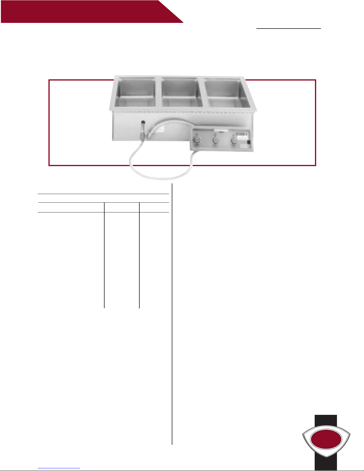
MOD-100TD - MOD-500TDM WAR MERS WITH AUTO WATER FILL
I T E M N O .
W E L L S M A N U F A C T U R I N G
Features
• All models have an automatic water fill
system that maintains the proper water level in
each pan through the use of a water sensor and
solenoid valve.
• Individual controls for each well give the
warmers maximum versatility.
• Thermostats are combined with higher wattage
elements to provide quicker heat-up and
faster recovery.
• Fully insulated for greater efficiency.
• A one-inch diameter drain manifold
(DM models) is provided to allow for a single
drain connection at the left or right front corner.
MOD-100TD has a one-half inch drain.
• Each well is one-piece, deep-drawn, stainless
steel for maximum strength and durability.
• Warmers are designed for wet operation only.
• Wellslok allows for quick and easy installation
in stainless steel countertops.
• The MOD Series Warmers are Underwriters
Laboratories, Inc. LISTED and meet NSF
International and Canadian standards.
• A one-year warranty against defects covers
parts and labor.
MOD-100TD, 200TDM, 300TDM, 400TDM, 500TDM
WARMERS WITH AUTO WATER FILL
Accessories / Options
Wellslok Extension Kit, designed for installation
in countertops up to 1-1/2” thick, refer to
installation instructions, 22593
Drain Valve Extension Kit, extension from
drain to counter front with remote handle,
for use with MOD-100TD only, 20385
Drain Screen, 21709
Optional 72” Wiring, thermostatically controlled
warmers, priced per well, contact factory
MOD-300TDM
Explanation of Built-In Warmer Suffixes:
TD ............. thermostatically controlled/with drain
TDM .........thermostatically controlled/with drain/
connected to drain manifold
WELLS
(44)
1 3/4
(356)
14
(197)
7 3/4
(248)
9 3/4
(159)
6 1/4
(889)
35
(1105)
43 1/2
(600)
23 5/8
(57)
2 1/4
CONNECTION
WATER LINE
EXTERNAL NPT
1/4 INCH
MANIFOLD EACH END
INTERNAL NPT
1 INCH
TYP
E6070STD.4
R
E6070
R
LISTED
R
(44)
1 3/4
(356)
14
(197)
7 3/4
(248)
9 3/4
(159)
6 1/4
(457)
18
(749)
29 1/2
(600)
23 5/8
(57)
2 1/4
MANIFOLD EACH END
INTERNAL NPT
1 INCH
CONNECTION
WATER LINE
EXTERNAL NPT
1/4 INCH
E6070STD.4
R
E6070
R
LISTED
R
(187)
7 3/8
(44)
1 3/4
(248)
9 3/4
(159)
6 1/4
(356)
14
(375)
14 3/4
(597)
23 1/2
(57)
2 1/4
LINE CONNECTION
NPT WATER
EXTERNAL
1/4 INCH
INTERNAL NPT
1/2 INCH
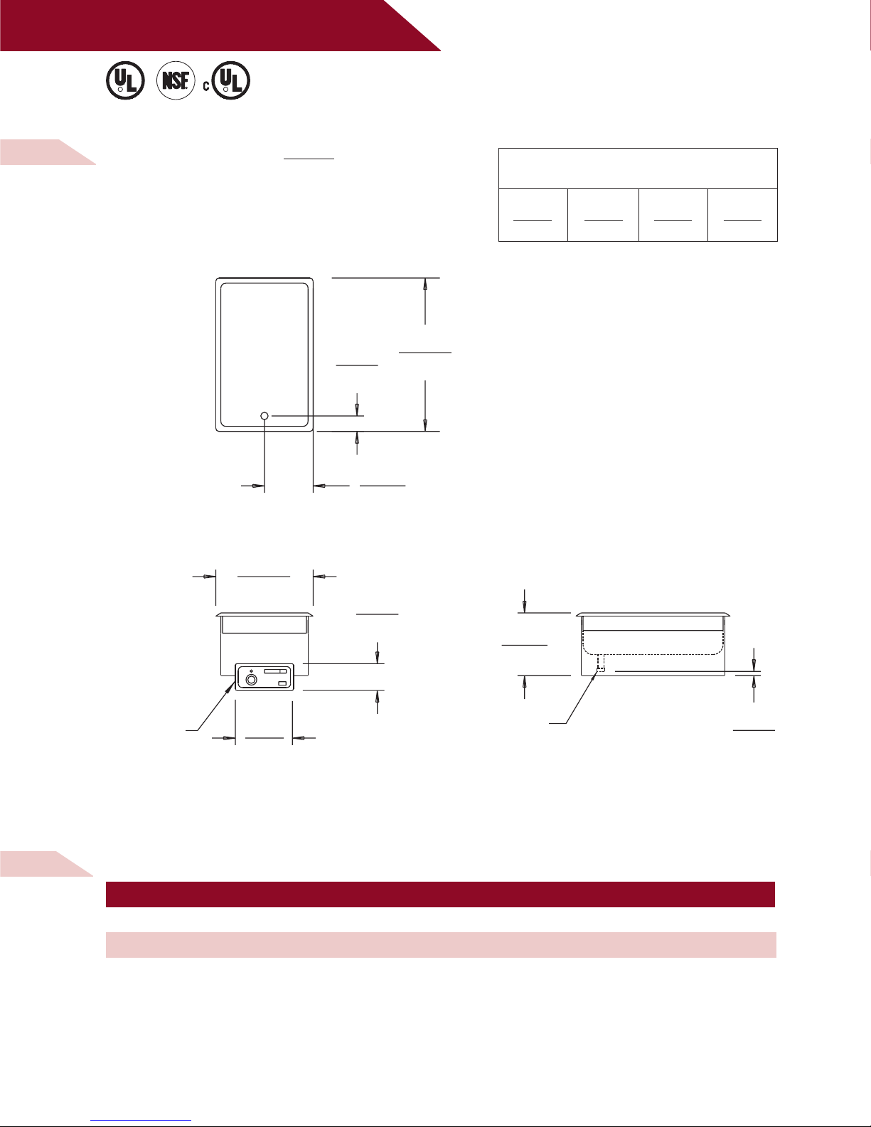
M O D E L
M O D - 1 0 0 T D
WA R M E R W I T H A U T O W A T E R F I L L
D I M E N S I O N S :
INCH
(MM)
W E L L S M A N U FA C T U R I N G
MINIMUM CLEARANCE REQUIRED FROM
UNIT TO THE NEAREST SURFACE
BACK SIDE BOTTOM FRONT
1 1 6 3/4 4 1/8
(25) (25) (171) (105)
M O D - 1 0 0 T D E L E C T R I C A L S P E C I F I C A T I O N S :
MOD-100TD/AF 208 1240 6.0 SINGLE NONE
MOD-100TD/AF 240 1650 6.9 SINGLE NONE
MODELS VOLTS WATTS AMPS PHASE POWER SUPPLY CORD
NOTE: Specifications are subject to change without notice. See installation instructions prior to installing the unit.
This document is not for installation purposes.
E6070STD.4
R
E6070
R
LISTED
R
02 /0 2 • RE V( -) • PAR T NO. 3034 38 02 /0 2 • RE V( -) • PAR T NO. 3034 38 02 /0 2 • RE V( -) • PAR T NO. 3034 38
 Loading...