

Page 1
WELLS BLOOMFIELD, LLC
10 Sunnen Dr., St. Louis, MO 63143
telephone: 888-356-5362
fax: 314-781-2714
www.wells-mfg.com
273
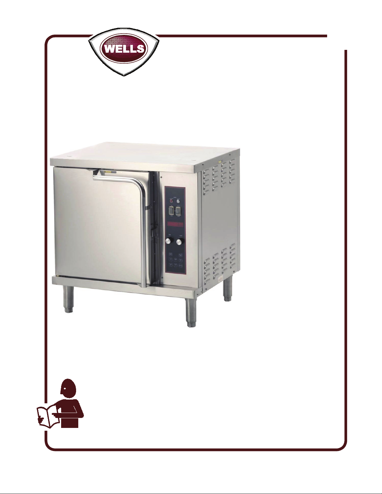
OWNERS MANUAL
HALF-SIZE
CONVECTION
OVEN
MODELS
OC1
OC1
Includes
INSTALLATION
USE & CARE
EXPLODED VIEW
PARTS LIST
WIRING DIAGRAM
IMPORTANT: DO NOT DISCARD THIS MANUAL
This manual is considered to be part of the appliance and is to be given to the OWNER or
MANAGER of the restaurant, or to the person responsible for TRAINING OPERATORS of
this appliance. Additional manuals are available from your WELLS DEALER.
THIS MANUAL MUST BE READ AND UNDERSTOOD BY ALL PERSONS USING OR
INSTALLING THIS APPLIANCE. Contact your WELLS DEALER if you have any
questions concerning installation, operation or maintenance of this equipment.
p/n 2M-Z14729 Rev. - M273 110519
Page 2

LIMITED WARRANTY STATEMENT
Unless otherwise specied, all commercial cooking
equipment manufactured by WELLS BLOOMFIELD, LLC is
warranted against defects in materials and workmanship
for a period of one year from the date of original installation
or 18 months from the date of shipment from our factory,
whichever comes rst, and is for the benet of the original
purchaser only.
THIS WARRANTY IS THE COMPLETE AND ONLY
WARRANTY, EXPRESSED OR IMPLIED IN LAW OR IN
FACT, INCLUDING BUT NOT LIMITED TO, WARRANTIES
OF MERCHANTABILITY OR FITNESS FOR ANY
PARTICULAR PURPOSE, AND/OR FOR DIRECT,INDIRECT
OR CONSEQUENTIAL DAMAGES INCONNECTION WITH
WELLS BLOOMFIELD PRODUCTS. This warranty is void
if it is determined that, upon inspection by an authorized
service agency, the equipment has been modied, misused,
misapplied, improperly installed, or damaged in transit or
by re, ood or act of God. It also does not apply if the serial
nameplate has been removed, or if service is performed
by unauthorized personnel. The prices charged by Wells
Bloomeld for its products are based upon the limitations in
this warranty. Seller’s obligation under this warranty is limited
to the repair of defects without charge by a Wells Bloomeld
factory authorized service agency or one of its sub-service
agencies. This service will be provided on customer’s
premises for non-portable models. Portable models (a device
with a cord and plug) must be taken or shipped to the closest
authorized service agency, transportation charges prepaid,
for service. In addition to restrictions contained in this
warranty, specic limitations are shown in the Service Policy
and Procedure Guide. Wells Bloomeld authorized service
agencies are located in principal cities. This warranty is valid
in the United States and Canada and void elsewhere. Please
consult your classied telephone directory, your foodservice
equipment dealer or contact:
Wells Bloomeld, LLC
10 Sunnen Dr., St. Louis MO 63143 USA
phone (314) 781-2777 or fax (314) 781-2714
for information and other details concerning warranty.
SERVICE POLICY AND PROCEDURE GUIDE and ADDITIONAL WARRANTY EXCLUSIONS
1. Resetting of safety thermostats, circuit breakers, over
load protectors, and/or fuse replacements are not
covered by this warranty unless warranted conditions
are the cause.
2. All problems due to operation at voltages or phase
other than specied on equipment nameplates are not
covered by this warranty. Conversion to correct voltage
and/or phase must be the customer’s responsibility.
3. All problems due to electrical connections not made
in accordance with electrical code requirements
and wiring diagrams supplied with the equipment are
not covered by this warranty.
4. Replacement of items subject to normal wear, to
include such items as knobs, light bulbs; and, normal
maintenance functions including adjustments of
thermostats, adjustment of micro switches and
replacement of fuses and indicating lights are not
covered by warranty.
5. Damage to electrical cords and/or plug due to exposure
to excessive heat are not covered by this warranty.
6. Full use, care, and maintenance instructions supplied
with each machine. Noted maintenance and
preventative maintenance items, such as servicing and
cleaning schedules, are customer responsibility. Those
miscellaneous adjustments noted are customer
responsibility. Proper attention to preventative
maintenance and scheduled maintenance procedures
will prolong the life of the appliance.
7. Travel mileage is limited to sixty (60) miles from an
Authorized Service Agency or one of its sub-service
agencies.
8. All labor shall be performed during regular working
hours. Overtime premium will be charged to the buyer.
9. All genuine Wells replacement parts are warranted
for ninety (90) days from date of purchase on nonwarranty equipment. This parts warranty is limited only
to replacement of the defective part(s). Any use of
non-genuine Wells parts completely voids any
warranty.
10. Installation, labor, and job check-outs are not
considered warranty and are thus not covered by this
warranty.
11. Charges incurred by delays, waiting time or operating
restrictions that hinder the service technician’s ability to
perform service are not covered by warranty. This
includes institutional and correctional facilities.
SHIPPING DAMAGE CLAIM PROCEDURE
NOTE: For your protection, please note that equipment
in this shipment was carefully inspected and packaged
by skilled personnel before leaving the factory. Upon
acceptance of this shipment, the transportation company
assumes full responsibility for its safe delivery.
IF SHIPMENT ARRIVES DAMAGED:
1. VISIBLE LOSS OR DAMAGE: Be certain that any
visible loss or damage is noted on the freight bill or
express receipt, and that the note of loss or damage is
signed by the delivery person.
2. FILE CLAIM FOR DAMAGE IMMEDIATELY:
Regardless of the extent of the damage.
3. CONCEALED LOSS OR DAMAGE: if damage is
unnoticed until the merchandise is unpacked, notify the
transportation company or carrier immediately, and le
“CONCEALED DAMAGE” claim with them. This
should be done within fteen (15) days from the date
the delivery was made to you. Be sure to retain the
container for inspection.
Wells Bloomeld cannot assume liability for damage or loss
incurred in transit. We will, however, at your request, supply
you with the necessary documents to support your claim.
M273 p/n 2M-Z14729 Owners Manual OC1 Half-Size Convection Ovens
xi
Page 3
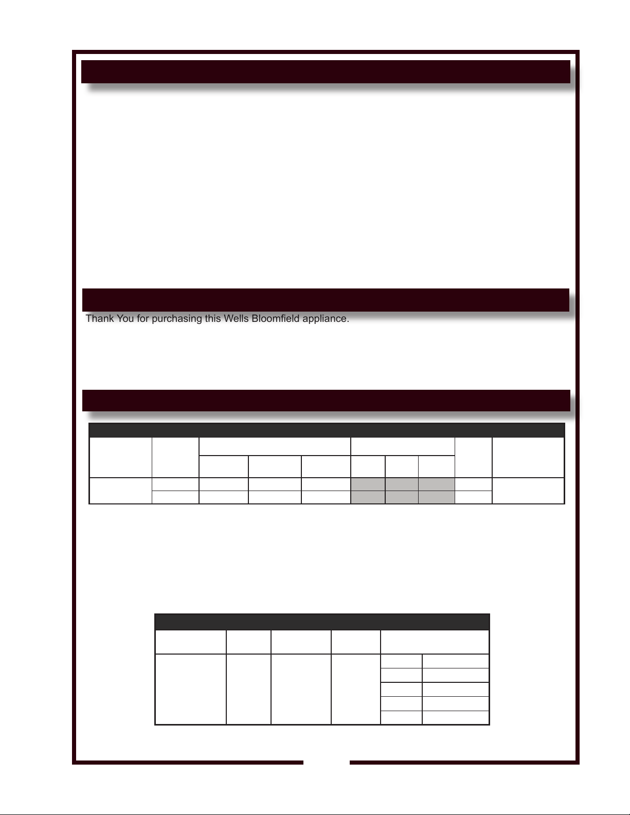
TABLE OF CONTENTS
WARRANTY xi
SPECIFICATIONS 1
FEATURES & OPERATING CONTROLS 2
PRECAUTIONS & GENERAL INFORMATION 4
INSTALLATION 5
AGENCY APPROVAL INFORMATION 5
OPERATION 8
COOKING SUGGESTIONS 10
CLEANING INSTRUCTIONS 11
TROUBLESHOOTING SUGGESTIONS 13
PREVENTATIVE MAINTENANCE 14
EXPLODED VIEW & PARTS LIST 16
WIRING DIAGRAM 21
PARTS & SERVICE 25
CUSTOMER SERVICE DATA 25
INTRODUCTION
Thank You for purchasing this Wells Bloomeld appliance.
Proper installation, professional operation and consistent maintenance of this appliance will ensure that it
gives you the very best performance and a long, economical service life.
This manual contains the information needed to properly install this appliance, and to use and care for the
appliance in a manner which will ensure its optimum performance.
SPECIFICATIONS
MODEL VOLTS
OC1
M273 p/n 2M-Z14729 Owners Manual OC1 Half-Size Convection Ovens
208 1ø 5000 NONE 5000 24
240 1ø 5600 NONE 5600 24
HEIGHT WIDTH DEPTH
30-1/4” (768mm)
plus 6” (152mm)
legs or casters
OVEN HOTPLATES TOTAL L1 L2 L3
SPECIFICATIONS
WATTS AMPS PE R LEG 3ø
DIMENSIONS
30-1/4”
(768mm)
26-1/4” (641mm)
plus 1-13/16”
(46mm) handle
DOOR
SWING
21” (635mm)
radius
REQUIRED CLEARANCES
Bottom 6” (152mm)
AMPS
Front 21” (533mm)
Top n/a
Back 3” (76mm)
Sides 3” (76mm)
1ø
POWER
SUPPLY
CORD
NEMA 6-30P
1
Page 4
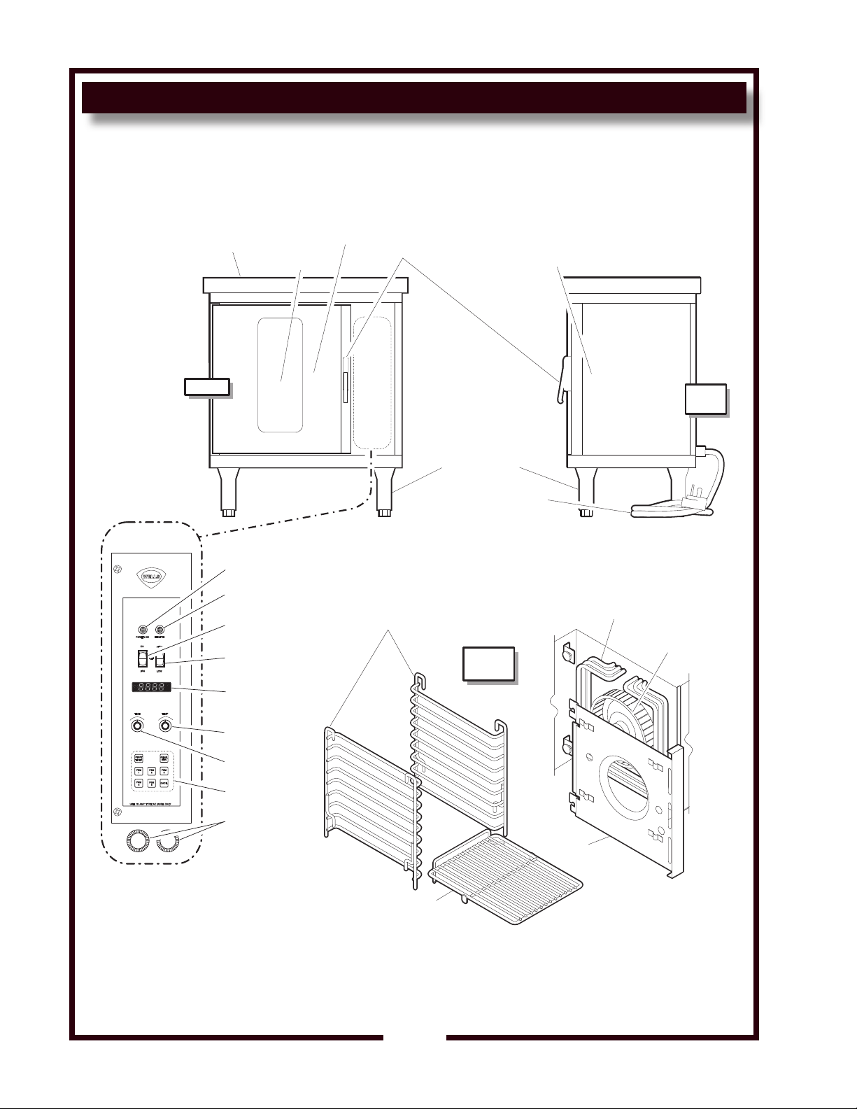
FEATURES & OPERATING CONTROLS
START
TIMER
PGM
1
PGM
4
PGM
5
CANCEL
PGM3PGM
2
ACTUAL
TEMP.
POWER ON
ON
FAN
OFF
HIGH
LOW
HEAT ON
PREP TOP
(OPTIONAL)
OVEN DOOR
LATCH
RIGHT SIDE
ACCESS PANEL
CONTROL
PANEL
POWER
INDICATOR
HEAT
INDICATOR
ON-OFF-FAN
SWITCH
FAN HIGH-LOW
SWITCH
DIGITAL
DISPLAY
TEMP SET
DIAL
TIME SET
DIAL
PROGRAM
KEYS
FUSES
RACK SUPPORTS
FAN
BAFFLE
OVEN
RACK
HEATING
ELEMENTS
BLOWER
FAN
VIEWING
WINDOW
ADJUSTABLE
LEGS
POWER
CORD
RIGHT
SIDE
FRONT
INSIDE
OVEN
IL2253
Fig. 1 Features & Operating Controls
M273 p/n 2M-Z14729 Owners Manual OC1 Half-Size Convection Ovens
2
Page 5
FEATURES & OPERATING CONTROLS (continued)
IL2254
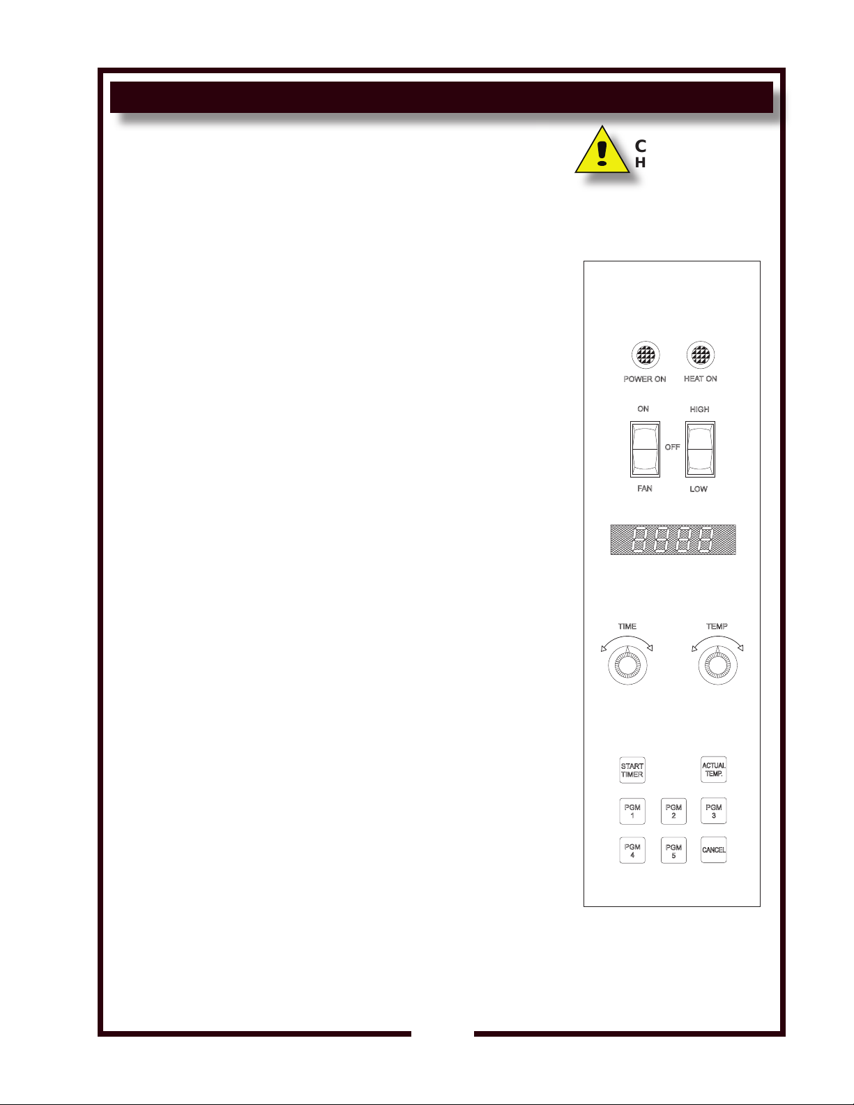
FEATURES & OPERATING CONTROLS
OVEN POWER SWITCH (ON-OFF-FAN):
1. ON position (with door closed). POWER ON indicator will glow,
blower fan will come on and unit will start to heat.
NOTE: In the ON position, if the door is opened, blower fan is
turned off and heating elements are de-energized.
2. FAN position. Blower fan will run (regardless of door position).
Heating elements are not energized.
SUGGESTION: For faster cool-down, prop door open and place
power switch in FAN position.
3.
OFF position shuts off power and blower fan.
OVEN FAN SPEED SWITCH (HIGH-LOW):
1. HIGH for normal operation.
2. LOW for foods sensitive to air currents.
3. OFF position shuts off blower fan
TIME ADJUSTMENT KNOB:
Used to program menu times
TEMP ADJUSTMENT KNOB
Used to program menu temperatures
page 9.)
DIGITAL DISPLAY
1. Displays set temperature or set time.
2. Displays temperature inside oven when ACTUAL TEMP key is
pressed.
3.
Displays set time and temperature of individual menu items when the
associated PGM key is pressed
4.
Displays time and temperature settings in programming mode.
(See PROGRAM COOK MODE, page 9.)
(See PROGRAM COOK MODE,
CAUTION:
HOT SURFACE
Exposed surfaces can be hot
to the touch and may cause
burns.
START TIMER KEY
Begins a cook cycle.
PROGRAM KEYS
Five different pre-set time/temperature combinations for preparing
different menu items.
CANCEL KEY
1. Press at any time to cancel a cook cycle.
2. Press at the end of a cook cycle to silence the audible alarm.
OVEN RACKS:
1. Five oven racks are provided with the oven.
2. Racks may be inserted into any available slot in the rack supports.
3. Always cook on a rack for proper convection air circulation.
4. Racks are designed to hold half-size (13” x 18”) bun pans.
M273 p/n 2M-Z14729 Owners Manual OC1 Half-Size Convection Ovens
3
Fig. 2 Control Panel
Page 6
PRECAUTIONS AND GENERAL INFORMATION
WARNING:
ELECTRIC
SHOCK HAZARD
All servicing requiring
access to non-insulated
electrical components
must be performed by
a factory authorized
technician.
DO NOT open any access
panel which requires the
use of tools. Failure to
follow this warning can
result in severe electrical
shock.
CAUTION:
RISK OF
DAMAGE
DO NOT connect or
energize this appliance
until all installation
instructions are read and
followed. Damage to the
appliance will result if
these instructions are not
followed.
CAUTION:
HOT SURFACE
Exposed surfaces can be
hot to the touch and may
cause burns.
This appliance is intended for use in commercial establishments only.
This appliance is intended to prepare food for human consumption.
No other use is recommended or authorized by the manufacturer or its
agents.
Operators of this appliance must be familiar with the appliance use,
limitations and associated restrictions. Operating instructions must be
read and understood by all persons using or installing this appliance.
Cleanliness of this appliance is essential to good sanitation. Read and
follow all included cleaning instructions and schedules to ensure the
safety of the food product.
Disconnect this appliance from electrical power before performing any
maintenance or servicing.
DO NOT submerge this appliance in water. This appliance is not jet
stream approved. Do not direct water jet or steam jet at this appliance,
or at any control panel or wiring. Do not splash or pour water on, in or
over any controls, control panel or wiring. Do not wash oor around
this appliance with water or steam jet.
Exposed surfaces of this appliance can be hot to the touch and may
cause burns.
Do not operate this appliance if the control panel is damaged. Do not
operate this appliance if the keypad section of the control panel is torn
or broken. Call your Authorized Wells Service Agent for service.
The technical content of this manual, including any wiring diagrams,
schematics, parts breakdown illustrations and/or adjustment
procedures, is intended for use by qualied technical personnel.
Any procedure which requires the use of tools must be performed by a
qualied technician.
This manual is considered to be a permanent part of the appliance.
This manual and all supplied instructions, diagrams, schematics,
parts breakdown illustrations, notices and labels must remain with the
appliance if it is sold or moved to another location.
This appliance is made in the USA. Unless otherwise noted, this
appliance has American sizes on all hardware.
AGENCY LISTING INFORMATION
This appliance conforms to NSF Standard 4 for sanitation only if
STD 4
E6070
installed in accordance with the supplied Installation Instructions and
maintained according to the instructions in this manual.
This appliance is Listed under UL File E6070.
M273 p/n 2M-Z14729 Owners Manual OC1 Half-Size Convection Ovens
4
Page 7

INSTALLATION
UNPACKING & INSPECTION
Carefully remove the appliance from the carton. Remove all protective
plastic lm, packing materials and accessories from the appliance
before connecting electrical power or otherwise performing any
installation procedure.
Carefully read all instructions in this manual including the Installation
Section before starting any installation.
Read and understand all labels and diagrams attached to the
appliance.
Carefully account for all components and accessories before discarding
packing materials. Store all accessories in a convenient place for later
use.
COMPONENTS
5 ea.
OVEN RACKS
2 ea. RACK SUPPORTS
1 ea. FAN BAFFLE
1 ea. VENT DUCT ASSEMBLY
ACCESSORIES
NOTE: DO NOT discard
the carton or other packing
materials until you have
inspected the appliance for
hidden damage and tested it
for proper operation.
Refer to SHIPPING DAMAGE
CLAIM PROCEDURE on the
inside front cover of this
manual.
WARNING:
RISK OF
INJURY
Installation procedures must
be performed by a qualied
technician with full knowledge
of all applicable electrical and
plumbing codes. Failure can
result in personal injury and
property damage.
1 ea.
LITERATURE PACKAGE
OPTIONAL ACCESSORIES
5F-22882 Stacking and Venting Kit
SERVICE TECHNICIAN INSTALLATION NOTES
1. Installation and start up should be performed by an authorized
installation company. Installer must record installation particulars
on the CUSTOMER SERVICE DATA form at the end of this
manual.
2. Verify that this equipment installation is in compliance with the
specications listed in this manual and with local code
requirements.
IMPORTANT:
It is the RESPONSIBILITY
OF THE INSTALLER to check
with the AUTHORITY
HAVING
jURISDICTION, in order to
verify compliance with local
codes and ordinances for
THIS SPECIFIC EQUIPMENT
INSTALLATION.
M273 p/n 2M-Z14729 Owners Manual OC1 Half-Size Convection Ovens
5
Page 8
INSTALLATION (continued)
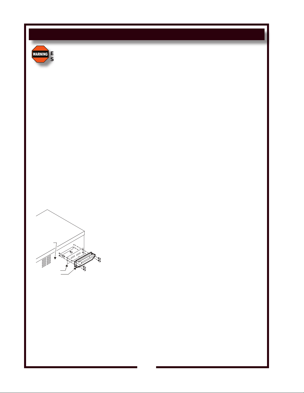
BACK OF
OVEN
BISCUIT ADAPTER
PROTEIN VENT
IL2255
WARNING:
ELECTRIC
SHOCK HAZARD
All servicing requiring access
to non-insulated electrical
components must be performed
by a factory authorized
technician.
DO NOT open any access
panel which requires the use
of tools. Failure to follow this
warning can result in severe
electrical shock.
NOTE: Oven is shipped with
biscuit baking adapter plate
attached to rear panel.
If oven is used exclusively for
bread products (bread, pies,
etc.), DO NOT remove adapter.
If oven is used for proteins,
remove adapter and install
external vent. Protein requires
additional venting to decrease
release of cooking vapors when
opening the door.
EQUIPMENT SET-UP
1. IF CONVECTION OVEN IS TO BE USED FOR PROTEINS,
INSTALL EXTERNAL DUCT
a. Remove two screws at each end of adapter plate on back of
oven.
b. Loosen two screws at bottom of adapter plate.
Remove adapter plate.
c. Slide bottom ange of vent duct over the two loosened screws.
d. Install four and tighten screws at ends of vent duct, then
tighten bottom screws.
2. CURB or COUNTER MOUNTING
a. Setup the appliance only on a rm, level, non-combustible
surface. Verify local codes for requirements. Concrete, tile,
terrazzo or metal surfaces are recommended. Metal over
combustible material may not meet code for non-combustible
surfaces.
b. Appliance is approved for installation with zero clearance at
bottom.
c. Recommend at least 3” clearance on sides and back to allow
adequate air ow.
3.
INSTALLING LEGS
a. Install adjustable legs, one on each corner of the appliance, in
the holes provided.
b. Set up the appliance only on a rm, level, non-combustible
surface. Verify local codes for requirements. Concrete, tile,
terrazzo or metal surfaces are recommended. Metal over
combustible material may not meet code for non-combustible
surfaces.
c. LEVELING: Verify that the appliance sits rmly on ALL FOUR
LEGS. With a spirit level, check that the appliance is level
front-to-back and side-to-side.
Fig. 3 Vent Duct Installation
4. INSTALLING OPTIONAL CASTERS
a. Install casters, one on each corner of the appliance, in the
holes provided. Locking casters must be installed on the
FRONT of the appliance.
b. Set up the appliance only on a rm, level, non-combustible
surface. Verify local codes for requirements. Concrete, tile,
terrazzo or metal surfaces are recommended. Metal over
combustible material may not meet code for non-combustible
surfaces.
c. LEVELING: Verify that the appliance sits rmly on all four casters
when in its normal operational position. With a spirit level, check
that the appliance is level front-to-back and side-to-side.
6
M273 p/n 2M-Z14729 Owners Manual OC1 Half-Size Convection Ovens
Page 9
INSTALLATION (continued)
IL2256
DANGER: ELECTRICAL SHOCK HAZARD
ELECTRICAL CONNECTIONS MUST BE MADE BY A
LICENSED ELECTRICIAN
Electrical shock will cause death or serious injury.
ELECTRICAL INSTALLATION
Refer to the nameplate on the front of the appliance.
• Verify the ELECTRICAL SERVICE POWER.
• Voltage and phase must match the nameplate specications, and
available electrical service amperage must meet or exceed the
specications listed on page 1.
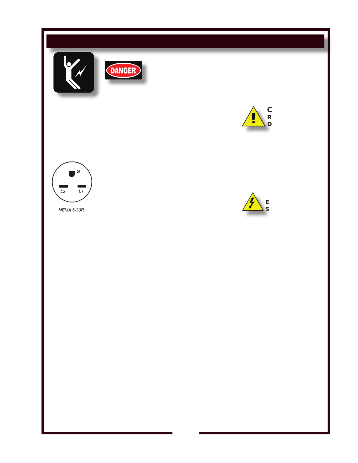
Fig. 4 Receptacle Conguration (not to scale)
208V and 240V OC-1 ovens are equipped with a NEMA 6-30P plug,
which must be plugged into a matching NEMA 6-30R receptacle.
The ground lug of the receptacle must be connected to a suitable
building ground.
IMPORTANT: Some jurisdictions require an electrical disconnect in
close proximity to the appliance. It is the responsibility of the installer
to meet this requirement.
PREPARATION
Prior to your rst use of this appliance, clean the entire appliance by
wiping all surfaces with a soft clean cloth moistened with warm clean
water and mild detergent. Rinse by wiping with clean water. Wipe dry
with a soft clean cloth.
CAUTION:
RISK OF
DAMAGE
DO NOT connect or energize
this appliance until all
installation instructions are
read and followed. Damage
to the appliance will result
if these instructions are not
followed.
CAUTION:
ELECTRICAL
SHOCK HAZARD
The ground prong of the
power cord is part of a
system designed to protect
you from electric shock in
the event of internal damage
to the NEVER CUT OFF
THE GROUND PRONG
(large round prong). NEVER
TWIST A PRONG TO FIT AN
EXISTING RECEPTACLE.
Contact a licensed electrician
to install an electrical
receptacle appropriate to
the voltage and amperage
requirements of the appliance.
The ground lug of 480V
appliances must be connected
to a suitable building ground.
M273 p/n 2M-Z14729 Owners Manual OC1 Half-Size Convection Ovens
IMPORTANT:
Damage due to being
connected to the wrong
voltage or phase is NOT
covered by warranty.
7
Page 10
OPERATION
IL2257 IL2257
CAUTION:
HOT SURFACE
Exposed surfaces can be hot
to the touch and may cause
burns.
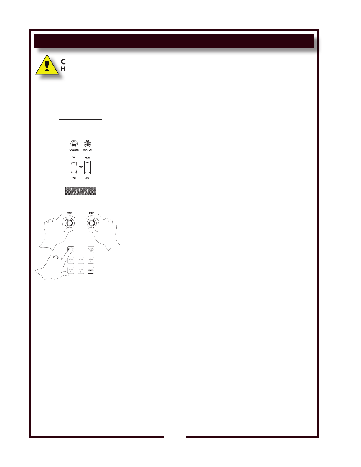
MANUAL COOK MODE
On ovens equipped with optional casters, be sure casters are locked
before turning power switch ON.
Congure oven racks as appropriate. Close the oven door.
Press oven power switch to ON. POWER ON indicator will glow.
Press fan switch to HIGH or LOW as required.
Rotate TEMP knob to the desired cooking temperature:
1. Range is 100ºF to 500ºF.
2. Turn clockwise to increase temperature, or counter-clockwise to
decrease set temperature in 5ºF intervals.
Digital display will show the set temperature, and will ash until
3.
the set temperature is reached.
Elements are energized as soon as the set temperature exceeds
4.
the actual temperature. HEAT ON indicator will glow.
SUGGESTION: The oven may be turned OFF without placing the
power switch in the OFF position by rotating the TEMP knob
counter-clockwise until the display shows zero degrees.
Rotate the TIME knob to the desired cooking time:
1.
Range is 5 seconds (00:05) to 12 hours (12:00).
Fig. 6 Manual Cook Mode
2. Turn clockwise to increase time, or counter-clockwise to
decrease time in 5 second intervals.
3. Time display digits and colon will ash until timer is started.
When the HEAT ON indicator goes out, oven is up to temperature.
Load product and close door.
Press START TIMER key.
1. Time display digits will stop ashing;
2. Time display colon will continue ashing for the duration of the
timed cycle.
At the end of the timed cycle, an audible alarm will sound.
3.
Press CANCEL key to silence the audible alarm.
M273 p/n 2M-Z14729 Owners Manual OC1 Half-Size Convection Ovens
8
Page 11
OPERATION (continued)
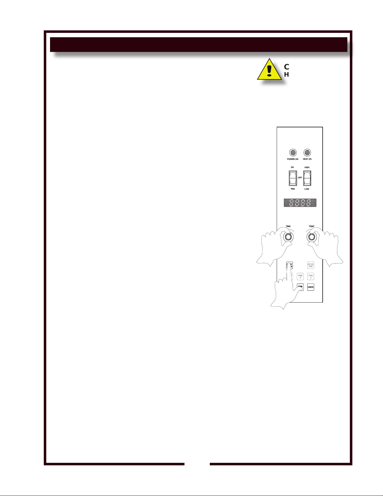
PROGRAM COOK MODE
Five programmable (PGM) keys are provided to allow presetting times
and temperatures for commonly cooked menu items:
1. Press and hold the appropriate PGM key and turn the TEMP
knob to the desired set temperature.
2. Continue to press and hold the appropriate PGM key and turn
the TIME knob to the desired cook time.
3. When the PGM key is released, the current temperature and
time settings are stored in memory.
4. The program for any PGM key may be displayed by
momentarily pressing that PGM key.
On ovens equipped with optional casters, be sure casters are locked
before turning power switch ON.
Congure oven racks as appropriate. Close the oven door.
Press power switch to ON. POWER ON indicator will glow.
Press fan switch to HIGH or LOW as required.
Preheat the oven in the manual cook mode.
Start a cook cycle by pressing the appropriate PGM key and START
TIMER key:
CAUTION:
HOT SURFACE
Exposed surfaces can be hot
to the touch and may cause
burns.
1.
Program keys and TEMP and TIME knobs are disabled during
the cooking cycle to prevent accidental re-programming.
2.
The actual oven temperature may be recalled by pressing the
ACTUAL TEMP key.
3. At the end of the timed cycle, an audible alarm will sound.
Press CANCEL key to silence the audible alarm.
TEMPERATURE OFFSET MODE
A user preference offset mode is provided should the displayed
temperature seem too hot or cold. This mode is used to adjust the
oven controlling temperature by plus or minus 35ºF, in 5ºF increments.
This adjustment affects the entire cooking range:
1. Rotate the TIME knob to set the time digits to 00:00
2. Rotate the TEMP knob to adjust the set temperature between
400ºF and 500ºF.
Press and hold the START TIMER key for 5 seconds.
3.
4. Turn either rotary knob until the desired offset is displayed.
5. Press the ACTUAL TEMP key to exit, and to store the offset in
memory.
Fig. 7 Program Cook Mode
M273 p/n 2M-Z14729 Owners Manual OC1 Half-Size Convection Ovens
9
Page 12
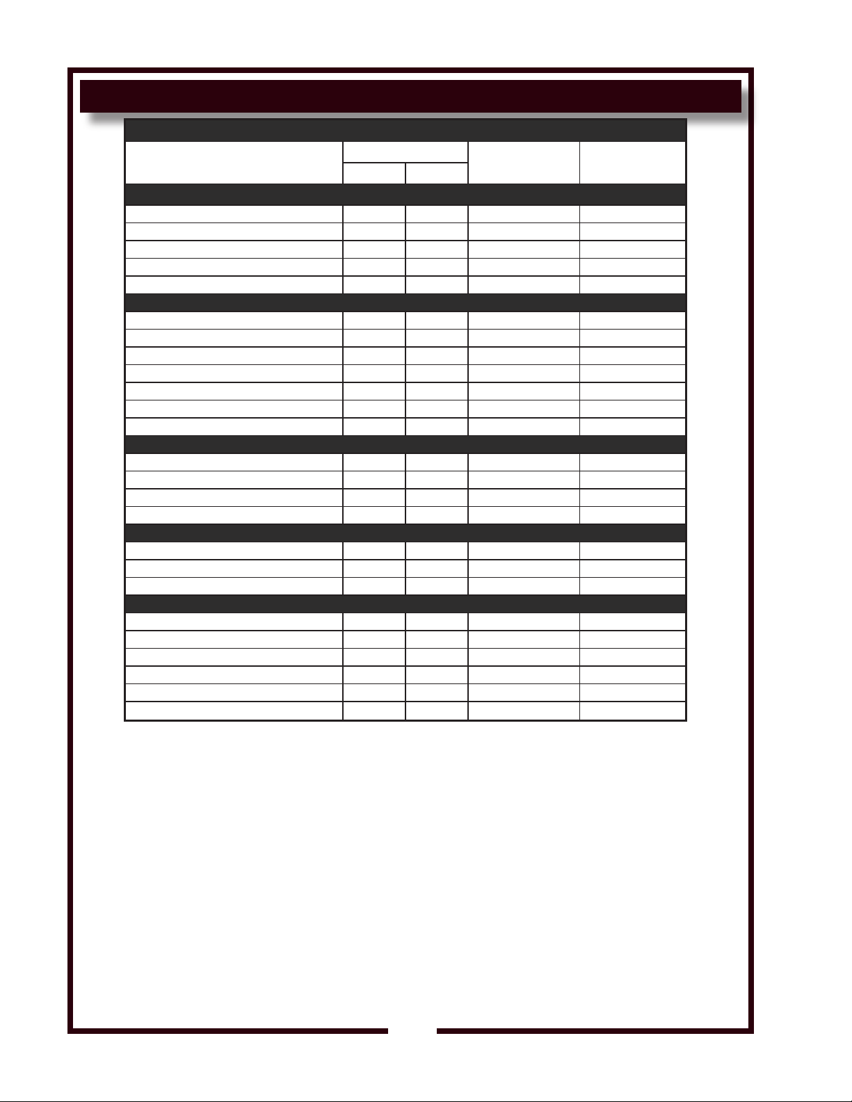
SUGGESTED TIMES & TEMPERATURES FOR BAKING AND ROASTING
SUGGESTED TIMES & TEMPERATURES FOR BAKING AND ROASTING
PRODUCT
BREAD PRODUCTS
Hamburger Rolls 300 149 15 5
Bread— 1 pound loaves 325 163 34 3 (12 loaves)
Rolls 300 149 16 5 (60 rolls)
Baking Soda Biscuits 400 204 7 3
Pizza 450 232 7 3
Sheet Cake (2-1/2 lbs per pan) 300 149 17 5
Frozen Fruit Pies (46 oz.) 350 177 50 5 (10 pies)
Frozen Fruit Pies (26 oz— 8” dia.) 350 177 40 5 (15 pies)
Sugar Cookies 300 149 15 5
Danish Rolls 350 177 12 5
Fruit Cakes 275 135 75 3
Cake— 1 pound 300 149 19 5 (10 cakes)
Fish Sticks 350 177 15 5
Lobster Tails 450 232 9 5
Halibut Steaks (Frozen 5 oz.) 350 177 20 5
Baked Shrimp (Stuffed) 400 204 7 5
Turkey, Rolled (18 lb. Rolls) 310 154 225 (3-3/4 hrs) 1
Chicken (2-1/2 lb. Quartered) 350 177 30-35 5
Chicken (Breasts) 350 177 30 5
Melted Cheese Sandwich 400 204 8 5
Idaho Potatoes (120) 450 232 40 5
Beef Pot Pies 400 204 30-35 5
Macaroni & Cheese 350 177 30 5
Turkey Pot Pies 400 204 30-35 5
TV Dinners 450 232 25 5
TEMP
°F °C
PASTRIES
FISH
FOWL
OTHER
TIME (MINUTES) NO. OF RACKS
NOTE: These cooking times and temperatures are suggestions only. Your own experience with
your equipment and menu items will be your best guide.
NOTE: HIGH fan speed provides the fastest cooking times. Use LOW fan speed for menu items
that are sensitive to air currents (e.g. meringues and soufés).
10
M273 p/n 2M-Z14729 Owners Manual OC1 Half-Size Convection Ovens
Page 13
CLEANING INSTRUCTIONS
INSIDE OVEN
FAN BAFFLE
RACK SUPPORT
IL2258
PREPARATION Allow oven to cool to 150ºF or less
FREQUENCY Daily
TOOLS Fiber Brush, Plastic Scouring Pad, Plastic Scraper
Mild Detergent, Conventional Oven Cleaner
,
Non-Abrasive Cleanser
Clean Soft Cloth / Sponge
Solution: 4 parts vinegar to 10 parts warm water
CLEANING
1. Turn POWER SWITCH to FAN. With the door held open, allow the
oven to cool. When the oven interior has cooled to 150ºF or less,
turn the POWER SWITCH to OFF.
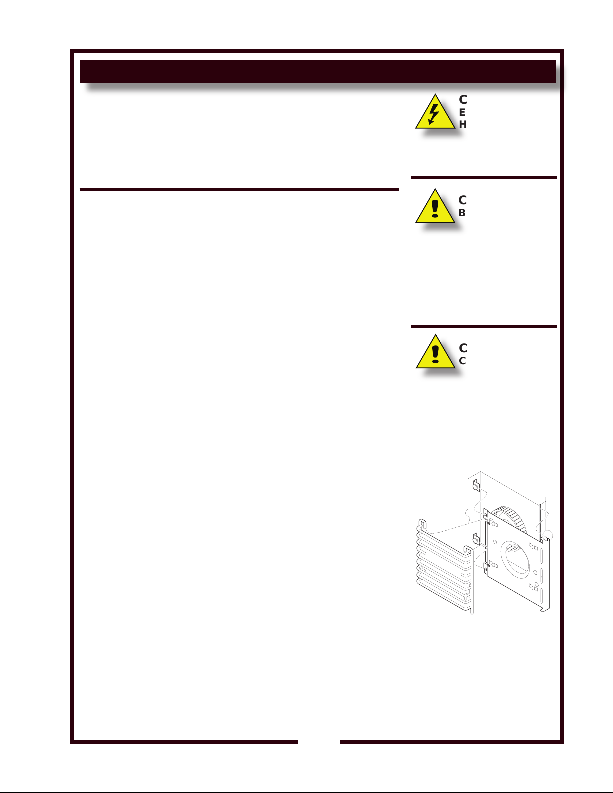
2. Remove racks and rack supports. Remove fan bafe.
3. Brush the fan wheel and wipe it with a moist cloth. Sponge out all
loose particles.
Scrub entire interior of convection oven with a plastic scouring pad
4.
and non-abrasive cleanser.
5.
For baked-on food spills, sparingly use a conventional oven
cleaner. Close the oven door, place the ON/OFF/FAN switch in the
OFF position. Let stand for 10 minutes.
Carefully wipe all cleaner and food residue from all interior
surfaces. Wipe the area with vinegar solution to neutralize the oven
cleaner.
6.
Wipe down the entire interior using a clean cloth or sponge moistened
with hot water and a mild detergent. Rinse by wiping with a cloth or
sponge moistened with clean water.
MPORTANT: Always wipe or rub in the direction of the polish lines or
grain of the metal.
CAUTION:
ELECTRIC SHOCK
HAZARD
Disconnect appliance
from electric power before
cleaning.
CAUTION:
BURN HAZARD
Allow appliance to cool
completely before cleaning.
Do not attempt to clean the
oven until it has cooled to
150ºF or less. It can burn
you. Hand protection is
required.
CAUTION:
CUT HAZARD
FAN BLADES ARE SHARP.
Use due care when cleaning
and/or wiping.
IMPORTANT:
Take care to avoid damage to
fan blades when reinstalling
fan bafe.
7. Clean oven racks and rack supports in a sink or dishwasher.
8. Reinstall the fan bafe, paying particular attention that the lip on the
right side of the fan bafe is fully seated in the slot in the edge of the
oven cavity. Reinstall rack supports and racks.
9.
Turn power switch to FAN . Verify that fan runs smoothly and does
not contact fan bafe. Turn power switch to OFF. Reposition fan bafe
if necessary.
10.
Replace rack supports and oven racks. Leave the door open
overnight.
12. Wipe down exterior of the oven using a soft cloth moistened with
clean water and a mild detergent. A plastic scouring pad may be
used to removed baked-on food debris. Rinse by wiping with a
cloth or sponge moistened with clean water.
IMPORTANT:
Always wipe or rub in the direction of the polish
lines or grain of the metal.
M273 p/n 2M-Z14729 Owners Manual OC1 Half-Size Convection Ovens
Procedure is complete
11
Fig. 8 Bafe & Rack Support
IMPORTANT: DO NOT spill
or pour water into controls,
control panel or wiring.
Damage to internal
components from water
damage is not covered by
warranty.
Page 14
TROUBLESHOOTING SUGGESTIONS
CAUTION: ELECTRICAL SHOCK HAzARD
Removal of any cabinet panel will result in exposed electrical circuits.
Any procedure requiring the removal of any cabinet panel must be performed
by a qualied technician only.
CAUTION: ELECTRICAL SHOCK HAzARD
Fuse replacement may expose dangerous voltages.
Fuse replacement must be performed by a qualied technician.
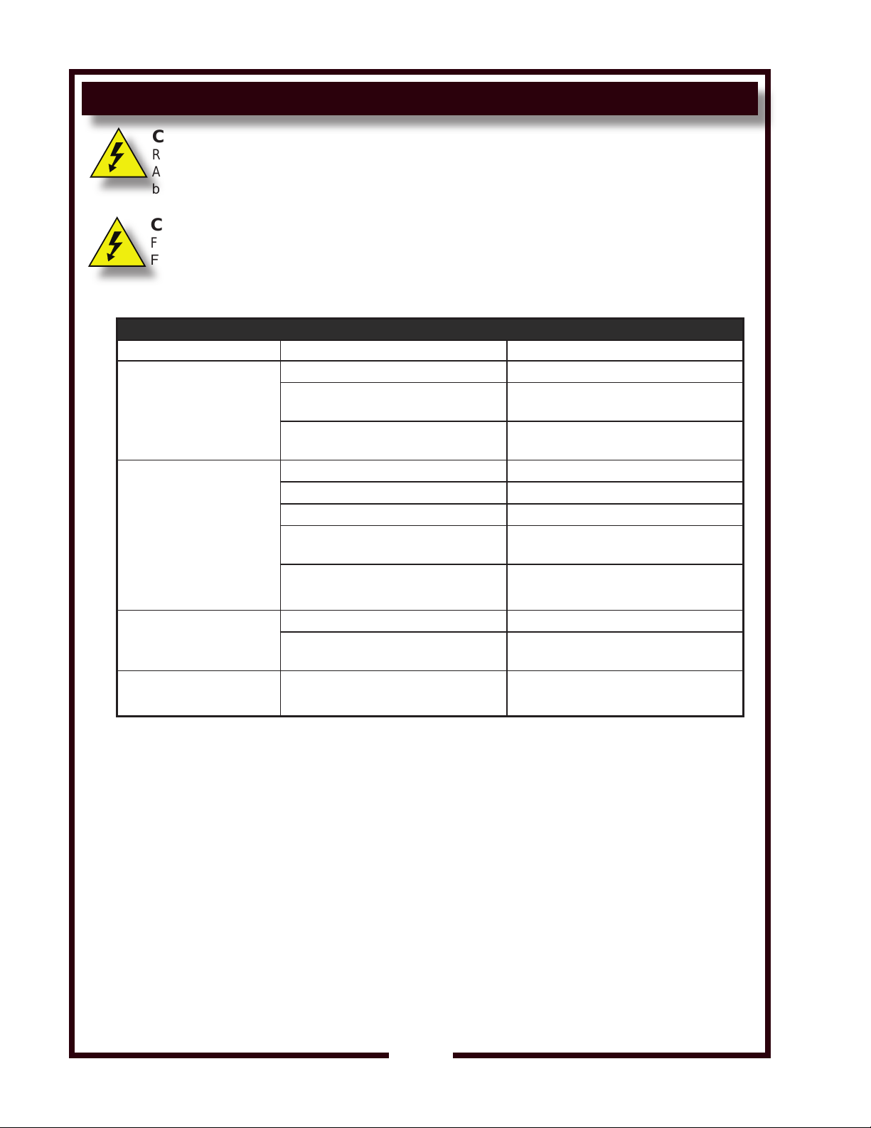
TROUBLESHOOTING
SYMPTOM POSSIBLE CAUSE SUGGESTED REMEDY
Circuit breaker off or tripped Reset circuit breaker
No power to appliance
Oven will not heat
Power cord unplugged or damaged
Fuse blown or loose
Power switch turned to OFF or FAN Turn power switch ON
Temperature control not set Set to desired temperature
Oven door not closed Be sure door is closed and latched
Hi-limit control tripped on excessive oven
temperature
Check power cord. Plug in or repair as
required
Check power fuses. If blown, correct
problem and replace fuses
Allow oven to cool, Hi-limit will reset
Damaged controller
Fan switch OFF Turn fan switch to HIGH or LOW
Blower fan will not run
Door pops open during cook
cycle
NOTE: There are no user serviceable components in the appliance. In all cases of damage or component malfunction,
Damage to internal components
Latch out of adjustment Adjust latch
contact your Authorized Wells Service Agency for repairs.
Contact Authorized Wells
Service Agency for repairs
Contact Authorized Wells
Service Agency for repairs
12
M273 p/n 2M-Z14729 Owners Manual OC1 Half-Size Convection Ovens
Page 15
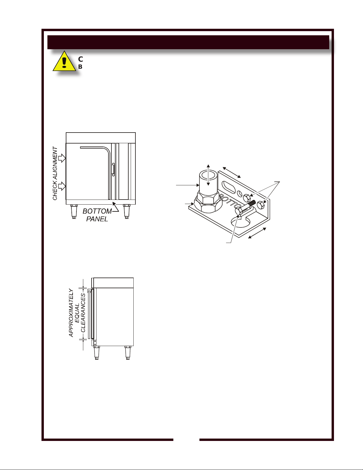
PREVENTATIVE MAINTENANCE
HEIGHT
ADJUSTMENT
PIVOT
PLUMB
JAMB NUT
HOLDING
SCREWS
ADJUSTING
BOLT
LEVEL
IL2259
CAUTION:
BURN HAZARD
Allow appliance to cool
completely before adjusting.
HINGE ADJUSTMENT
PRECAUTIONS: None
FREQUENCY: Monthly
TOOLS:
Phillips (+) Screwdriver
7/16” Nut Driver
7/8” and 1-1/8” Wrenches
THE FOLLOWING PROCEDURE IS TO BE PERFORMED BY
QUALIFIED PERSONNEL ONLY
1. Remove bottom panel to access pivot.
, at a Minimum; or, As Needed
Hinge Adjustment
M273 p/n 2M-Z14729 Owners Manual OC1 Half-Size Convection Ovens
2. Gap between top of door and frame , and between bottom
of door and frame must be approximately equal
Adjust height of door by loosening jamb nut, then turning
pivot on its screw mounting. Clockwise lowers the door
height. Re-tighten jamb nut .
3.
Gap between left side of door and frame must be the
same from top to bottom
Adjust door for plumb by loosening holding screws. Turn
adjusting bolt to increase or decrease gap at bottom.
Clockwise increases gap. Re-tighten holding screws.
Gap between top of door and frame must be the same
4.
from side to side
Adjust door for level by loosening holding screws, then
raising or lowering latch-end of door until it is level.
Re-tighten holding screws.
5.
Reinstall bottom panel.
Procedure is complete
13
Page 16
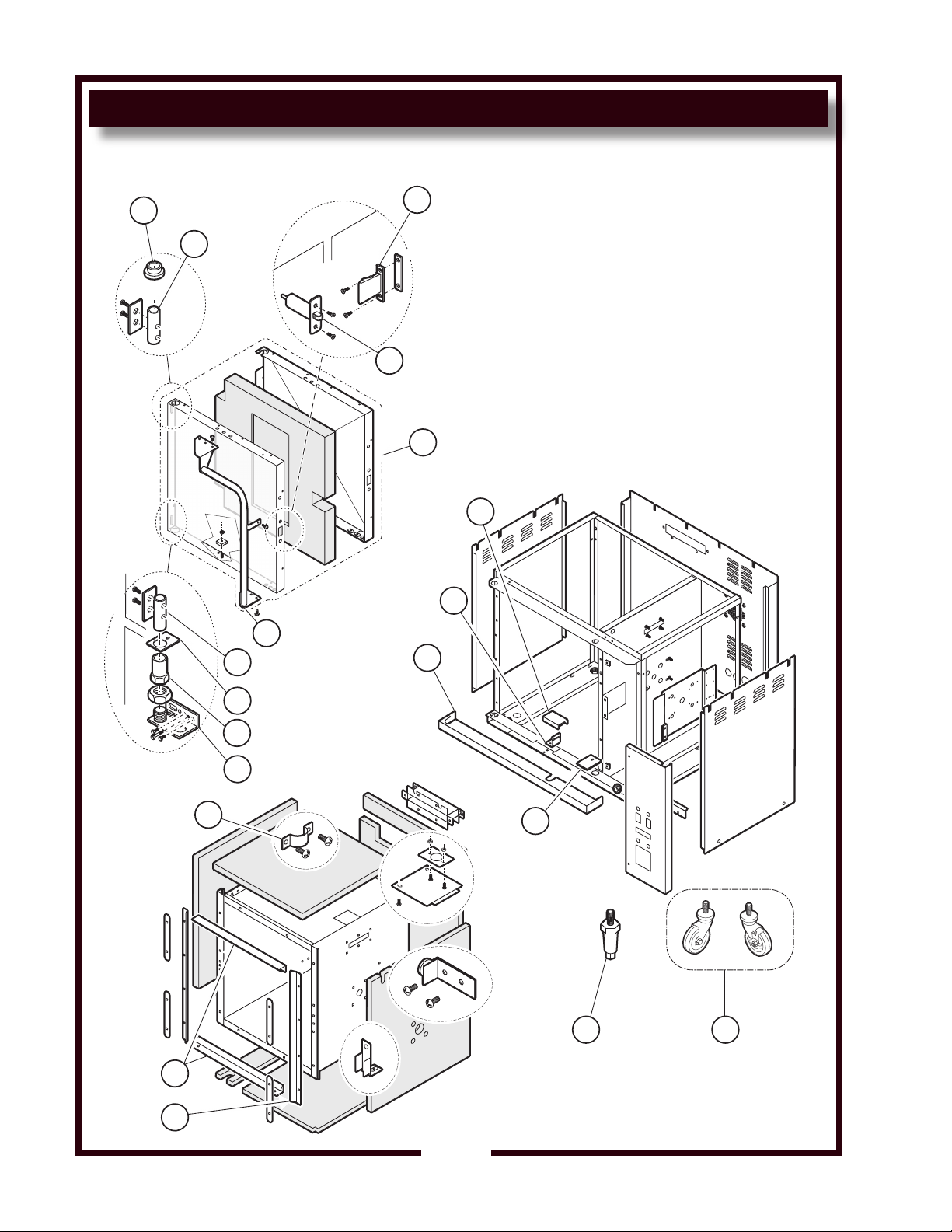
EXPLODED VIEW & PARTS LIST
Model: OC1, Cabinet Components
IL2262, Rev. -
CABINET DOOR
19
18
17
16
15
1
2
3
14
13
12
10
9
4
8
7
6 5
11
OC1 CABINET COMPONENTS
M273 p/n 2M-Z14729 Owners Manual OC1 Half-Size Convection Ovens
16
Page 17
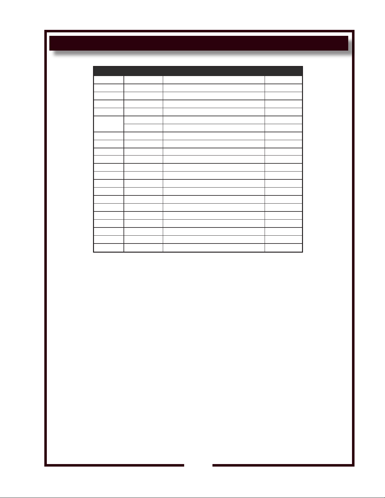
EXPLODED VIEW & PARTS LIST
OC1 ELECTRICAL COMPONENTS
Model OC1; Cabinet Components
Fig No Part No Description Qty
1 F6-45647 SHIELD PROX SWITCH ASSY O 1
2 F6-43787 BRKT SWITCH PROXIMITY 1
3 F6-43804 TRIM FR LOWER 1
4 F6-43899 PLATE DOOR PIVOT 1
5
6 2A-45598 LEG ADJUST 6IN SS OC-1 4
7 F6-46313 GASKET DOOR SIDE 2
8 F6-46314 GASKET DOOR TOP&BTM 2
9 F6-43889 CLIP SUPPORT RACK 8
10 F6-43896 HINGE BOT ASSY DOOR 1
11 2A-43900 SLEEVE HINGE DOOR 1
14 2R-305612 HANDLE ASSY 1
15 F6-304444 ASSY OVEN DOOR 1
16 2C-305615 LATCH ASSY 1
17 2C-305616 STRIKER LATCH 1
18 2A-305610 PIN HINGE DOOR OVENS 2
19 2K-305619 BUSHING UPPER DOOR HINGE 1
NI F6-43788 TOP OVEN 1
NI 2M-Z14730 WIRE DIAGRAM OC1 1
NI F6-49626 PANEL SIDE (LOUVERED) 2
5F-21372 CASTER SWVL W/BRAKE SET OF 2
5F-21330 CASTER SET CONV OVEN SET OF 4
M273 p/n 2M-Z14729 Owners Manual OC1 Half-Size Convection Ovens
17
Page 18
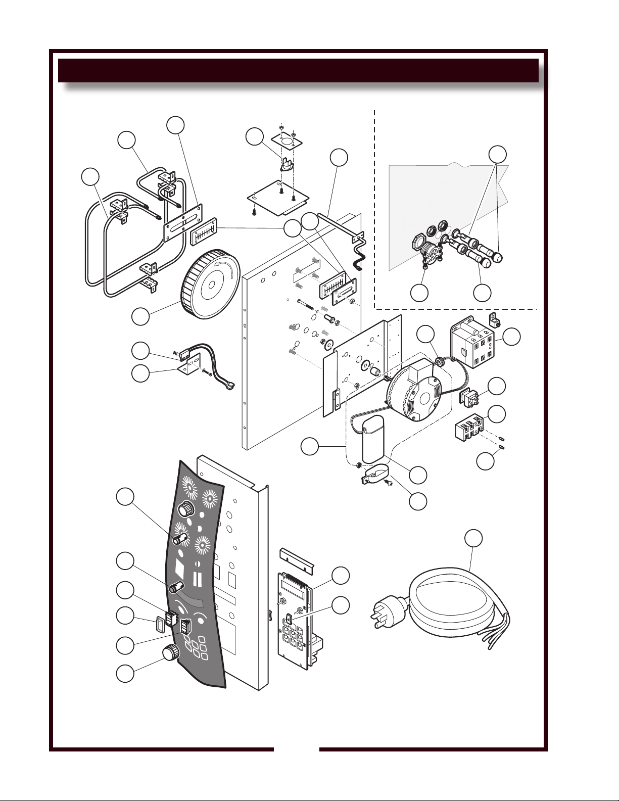
Model: OC1, Electrical Components
IL2261, Rev. -
BACK OF UNIT
17
16
18
14
13
12
11
10
9
8
15
7 6
5
2
4
1
3
28
29
30
27
26
25
24
23
22
21
20
19
SOME ITEMSS ARE INCLUDED FOR ILLUSTRATION PURPOSES
ONLY AND IN CERTAIN INSTANCES MAY DIFFER FROM ACTUAL
APPEARANCE OR MAY NOT BE AVAILABLE.
EXPLODED VIEW & PARTS LIST
OC1 ELECTRICAL COMPONENTS
M273 p/n 2M-Z14729 Owners Manual OC1 Half-Size Convection Ovens
18
Page 19
EXPLODED VIEW & PARTS LIST
OC1 ELECTRICAL COMPONENTS
Model OC1; Electrical Components
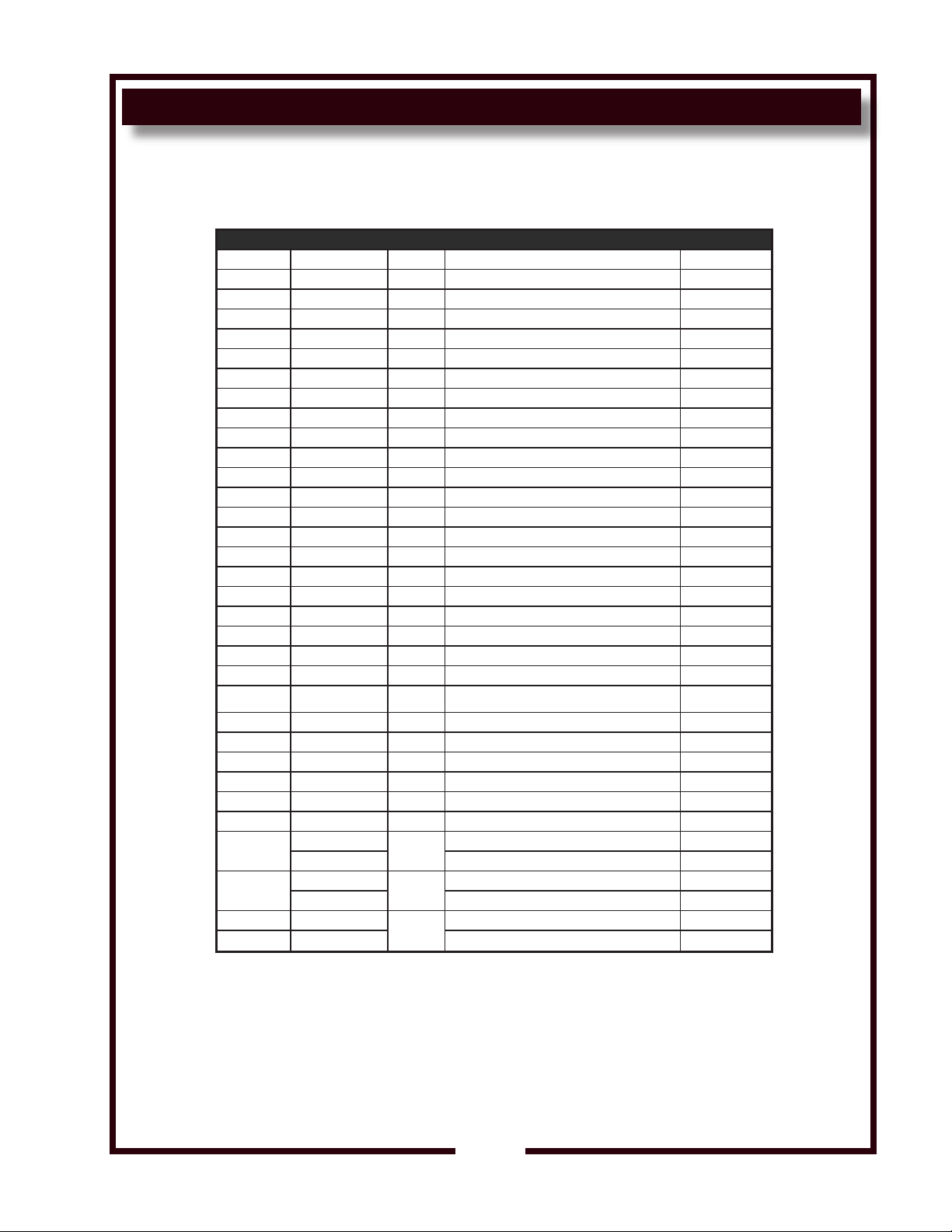
Fig No Part No Qty Description Application
1 2T-45180 1 THERMO SNAP DISC
2 2J-304712 1 PROBE TEMP OC-1
3 F6-43837 1 COVER GASKET ELEM OUTER M
4 2I-43834 2 GASKET ELEM M4200
5 2E-34769 2 FUSEHLDR HPG-EE 10A 240V
6 2E-34768 3 FUSE SC-10 10A 300V 34871
7 2K-300102 1 STRAIN RELIEF 1NPT.375-1.
8 2K-31040 2 BUSHING HEYCO 7/8 OD
9 2E-306967B 1 RELAY ESAFE II I/O 208/24
10 2E-43880 1 RELAY 208/240 DPDT
11 2E-37465 1 TERM BLOCK 3POLE 85AMP
12 2C-41974 2 NUT 8-32 HEX 7/8 LONG ALU
13 2E-Z13532 - CAPACITOR-MTR 370V@ 5mFD
14 2V-300933 1 BRKT CAPACITOR HOLDING
15 WS-63932 1 MOTOR 2SP 1/4HP 208/240V,w/CAP.
16 2J-304713 1 CONTROLLER TIME/TEMP OC-1
17 M3-303252 2 GASKET CLOSE CELL, OVEN P
18 2E-35259 1 CORD SET 250V 30A 12G 6-3
18 2R-47439 2 KNOB OC-1 RS
20 2E-45657 1 SWITCH SPDT OC-1
21 2E-43738 2 BOOT ROCKER SWITCH WB-2 B
22 2E-45651 1 SWITCH DPDT BLACK 250V 15
23 2J-31157 1 LIGHT SIGNAL RED M3938PR
24 2J-40877 1 LIGHT SIGNAL WHITE 250V 1
25 F6-43787 1 BRKT SWITCH PROXIMITY M42
26 F6-45239 1 PROXIMITY SWITCH ASSY M42
27 2U-43797 1 WHEEL BLOWER M4200
28 F6-43836 1 COVER GASKET ELEM INNER M
29
30
NI F6-45579
NI F6-45580 ELEM ASSY 240V OC1 240V
2N-43866UL
2N-43800UL ELEM 240V 2800W CENTER 240V
2N-43872UL
2N-43883UL ELEM 240V 2800W CENTER 240V
ELEM 208V 2500W CENTER 208V
1
ELEM 208V 2500W INNER 208V
1
ELEM ASSY 208V OC1 208V
1
M273 p/n 2M-Z14729 Owners Manual OC1 Half-Size Convection Ovens
19
Page 20
EXPLODED VIEW & PARTS LIST
Model: OC1, Removable Components
IL2263, Rev. -
1
2
3
OC1 REMOVABLE COMPONENTS
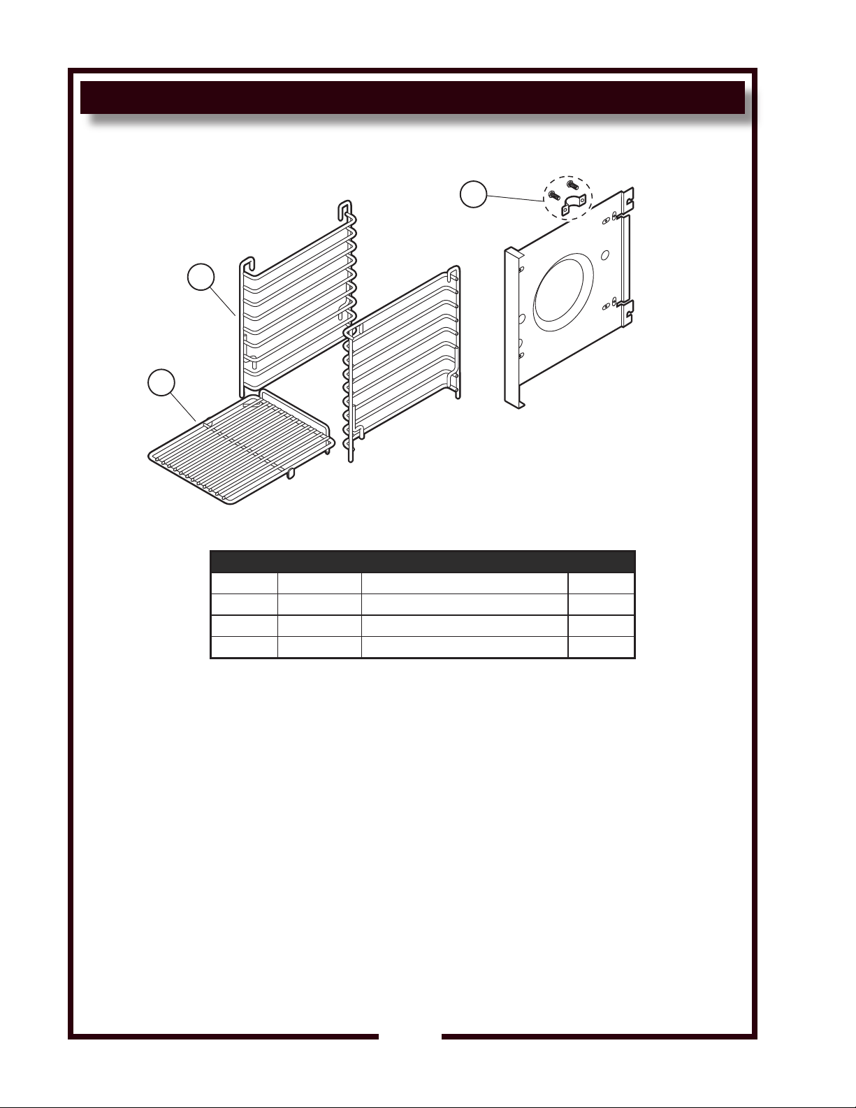
Model OC1; Removable Components
Fig No. Part No Description Qty
1 2B-50200-34 RACK HALF SIZE OVENS 5
2 2B-43785 SUPPORT RACK OVEN M4200 2
3 F6-43889 CLIP SUPPORT RACK M4200 8
M273 p/n 2M-Z14729 Owners Manual OC1 Half-Size Convection Ovens
20
Page 21
WIRING DIAGRAM
ATTACHMENT PLUG
NEMA 6-30
GRN
WHT.
BLK.
24
5.6
5.0
AMPS
KW
VOLTS
208
240 24
14
A1A2
T1
T2
L1
L2
74
75
13
12
11
4
5
77
77
1
72
A
B
87
4 5
21
2
15
SENSOR
8
27
L1
L2
29
26
17
20
19
21
DOOR RELAY
DOOR SWITCH
TERMINAL
BLOCK
1
3
4
6
L1L2
L3
16
41
15
16
22
24
7
41
23
25
37
18
33
29
28
35
37
31
39
ON-OFF-FAN
SWITCH
FAN HI-LO
SWITCH
WHITE HEAT
ON LIGHT
LIGHT ON
RED POWER
FAN
(3)
CONNECTOR
FUSE (2)
HI-LIMIT
AIR HEATER (2)
WHT.
BLK
RED
TIME/TEMP
CONTROL
28
OUTPUT
HYBRID
RELAY
2M-Z14730 REV -
2
5
HIGH LIMIT RELAY
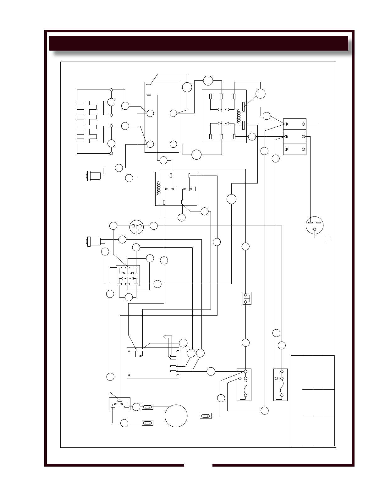
MODEL OC1 CONVECTION OVEN
M273 p/n 2M-Z14729 Owners Manual OC1 Half-Size Convection Ovens
21
Page 22

WIRING DIAGRAM
22
M273 p/n 2M-Z14729 Owners Manual OC1 Half-Size Convection Ovens
Page 23
PARTS & SERVICE
DESCRIPTION PART NO.
CASTERS (Set of 4 casters) 5F-21330
OVEN RACK Replacement 5F-21376
PREP TOP KIT 5F-21445
LEGS, 6” Stainless Steel (Set of 4 legs) 2A-22226
IMPORTANT: Use only
factory authorized service parts
and replacement lters.
For factory authorized service,
or to order factory authorized
replacement parts, contact
your Wells authorized service
agency, or call:
Wells Bloomeld, LLC
10 Sunnen Dr.,
St. Louis MO 63143 USA
Service Dept.
phone: (888) 356-5362
fax: (314) 781-2714
Service Parts Department
can supply you with the name
and telephone number of
the WELLS AUTHORI
SERVICE AGENCY
nearest you.
zED
RESTAURANT _____________________________ LOCATION _____________
INSTALLATION DATE ________________________ TECHNICIAN ___________
SERVICE COMPANY ________________________________________________
ADDRESS ___________________________ STATE ______ ZIP__________
TELEPHONE NUMBER (_____)_____-_________
EQUIPMENT MODEL NO. _______________EQUIPMENT SERIAL NO. _______________
VOLTAGE: (check one) 208 240
M273 p/n 2M-Z14729 Owners Manual OC1 Half-Size Convection Ovens
CUSTOMER SERVICE DATA
please have this information available if calling for service
23
Page 24
WELLS BLOOMFIELD, LLC
10 Sunnen Dr., St. Louis, MO 63143
telephone: 888-356-5362
fax: 314-781-2714
www.wells-mfg.com
 Loading...