

Wells MDW100 Quick Start Manual
MDW100 Modular Dry Well
Installation Instructions
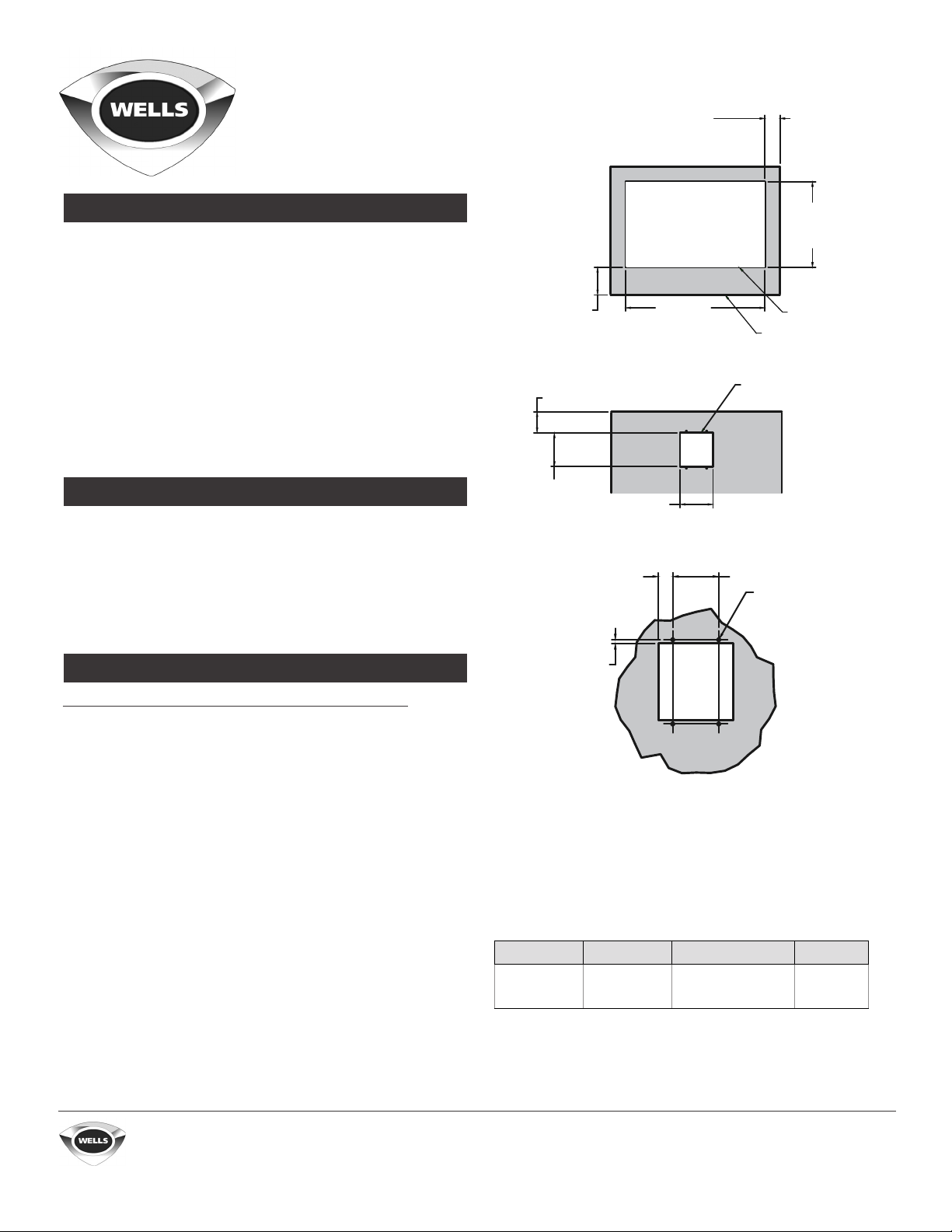
2.25 in. (57 mm)
minimum clearance
on non-control side
INSTALLATION REQUIREMENTS
Do not install closer than 4.125 inches (105 mm) to front wall,
one [1] inch (25 mm) to back and side walls, and 6.75 inches
(171 mm) to a surface below the unit. If storage is to be used
underneath, it is recommended that a bae be placed 8.5
inches (216 mm) below the unit to avoid contact with elevated
temperatures. The unit will need to be accessible from the
bottom after installation is complete.
A proper electrical connection based on the units electrical
specifications will be necessary for installation. This must
be wired and connected by a licensed electrician. Electrical
installation will need to pass local electrical codes.
FABRICATION
i. Lay out cutout dimensions on countertop and front apron.
ii. Lay out control panel mounting holes in counter apron using
the provided dimensions. The mounting holes should be
0.144 inch (3.7 mm) in diameter [drill size 27].
iii. Cut out the holes. On many countertops, reinforcement may
be needed to stiffen the countertop.
INSTALLATION INSTRUCTIONS
4.125 in. (105 mm)
minimum clearance
on control side
3.125 in.
(79 mm)
5 in.
(127 mm)
1/4 in.
(6 mm)
4.875 in.
(124 mm)
7/8 in.
(22 mm)
22.5 in.
(572 mm)
[A]
13.5 in.
(343 mm)
[B]
dry well cutout
countertop
control cutout
see detail A
3 in.
(76 mm)
0.144 inch ø
(3.7 mm ø)
[#27 drill]
Do not disconnect the control box from the modular unit.
i. Remove the knobs and faceplate from the control box. Pass the
control box through the countertop cutout, and then through
the apron cutout. This will require the box to be rotated so the
mounting tabs clear the hole. Next, lower and position the
modular section into countertop cutout.
ii.
Before final seating of modular section to countertop, apply
a bead of silicone sealant to the underside of the grey gasket
material supplied on the mounting flange. From underneath,
insert screwdriver into the slots in the Wellslok frame and twist
clockwise to move the ears outward as required to secure the
flange tightly to countertop.1
iii. Mount the control box to apron cutout using #10 sheet metal [or
wood] screws to the facing side where the holes were drilled.
iv. Run wiring through the conduit knockout to the terminal block,
making connection as shown in the unit’s wiring diagram to the
correct power source.
v. Mount the front panel onto the control box using the provided
hardware and place the knob on. At this point, you should be
able to power on the unit and check for proper operation.
LS BLOOMFIELD, LLC • www.wellsbloom ield.com
WEL
265 Hobson St
•
Smithville, Tennessee 37166
Telephone 888 356 5362 • Fax 314 781 5445
The unit’s overall depth is 12.125 inches (308 mm) will sit
approximately 11.75 inches (298 mm) below the counter
surface depending on counter thickness.
When installing multiple units, each unit will need a space
of at least 2.125 inches (54 mm) between the cutouts on
the long dimension sides [A] and at least 3.625 inches
(92 mm) between cutouts on the short dimension side [B].
MODEL TOTAL kW VOLTS, P HASE AMPS
MDW100
The supply wire will need to be the correct gauge as described by
the National Electrical Code and be rated to at least 167°F (75°C).
1 Wellslok adapter kit will use hex screws to tighten and allow
installation on countertops up to 1.5 inches (38 mm) thick.
0.61
0.8
208, 1Φ
240, 1Φ
Printed in the U.S.A. • 2M-Z2
The owner is responsible for proper installation as
described above. Please refer to the owner’s manual
for information regarding installation or use.
2.9
3.3
0755 • Rev B • 05.2018

Wellslok Mounting System
2M-302353 Basic Installation and Extension Kits
BASIC USE
BASIC USE
HSW, HT, HW, MDW, MOD, and SS series of round or rectangular,
top-mounted, built-in warmers come equipped with the Wellslok
mounting system. After getting the warmer positioned correctly
into the cutout with the appropriate gasket(s) and sealant applied,
as described in the installation instructions for the unit, access the
underside and turn each Wellslok tab outward with a screwdriver
as shown on the right to secure the warmer to the counter. On
countertops thicker than 16 GA steel, Wellslok extension kit[s]
will be needed. These kits can accommodate countertops up to
1.5 inches (38 mm) thick. Wellslok extension kits can only be
used with UL listed warmers approved for installation in wood
countertops. When installing in custom countertops, please
follow the manufacture’s “suggested” recommendations or
guidelines for installation of heated equipment in their counter
material”.
RECTANGULAR EXTENSION KITS
Rectangular extension kits [number 22593] come with hardware
to secure a single well up to 12 inches (305 mm) by 20 inches (508
mm) in size. For multiple-well models, additional kits will be required.
If your unit is a 4- or 5-well model, then you will need 3 kits for
proper installation. On 2- or 3-well models, you will need 2 kits for
proper installation. The clips will need to be attached under the
countertop and be positioned equally around the unit to assure
proper seating. Once all are in place tighten screws until they are
flush against the underside of the counter and the unit is secured
in place. On some materials, you may wish to place something
in between the tip of the screw and the countertop to prevent
marring the countertop material.
ROUND EXTENSION KITS
rectangular warmer shown
from underneath
gasket
warmer
Wellslok
Wellsloks
Wellslok extension kit
sealant
countertop
mounting screw
Round extension kits [number 22592] come with hardware
to secure one well. The clips will need to be attached under the
countertop and be positioned equally around the unit to assure
proper seating. Once all are in place tighten screws until they are
flush against the underside of the counter and the unit is secured
in place. On some materials, you may wish to place something
in between the tip of the screw and the countertop to prevent
marring the countertop material.
LS BLOOMFIELD, LLC • www.wellsbloom ield.com
WEL
265 Hobson St
•
Smithville, Tennessee 37166
Telephone 888 356 5362 • Fax 314 781 5445
mounting clip
KIT
22593 10 10
22592 6 6
QUANTITY OF
MOUNTING CLIPS
Printed in the U.S.A. • 2M-Z2
The owner is responsible for proper installation as
described above. Please refer to the owner’s manual
for information regarding installation or use.
QUANTITY OF
SCREWS
0755 • Rev B • 05.2018
 Loading...