

Weller wsd 161, wsl 2 Operating Instructions Manual

Weller
®
WSD 161 / WSL 2
Betriebsanleitung
Mode d’emploi
Gebruiksaanwijzing
Istruzioni per l’uso
Operating Instructions
Instruktionsbok
Manual de uso
Betjeningsvejledning
Manual do utilizador
Käyttöohjeet
D
F
NL
I
GB
E
S
DK
P
FIN
Οδηγίες Λειτουργίας
Kullan∂m k∂lavuzu
Návod k pouÏití
Instrukcja obs∏ugi
Üzemeltetési utasítás
Návod na pouÏívanie
Navodila za uporabo
Kasutusjuhend
Naudojimo instrukcija
Lieto‰anas instrukcija
GR
TR
CZ
PL
H
SLO
SK
EST
LT
LV
GBI
NL
F
D
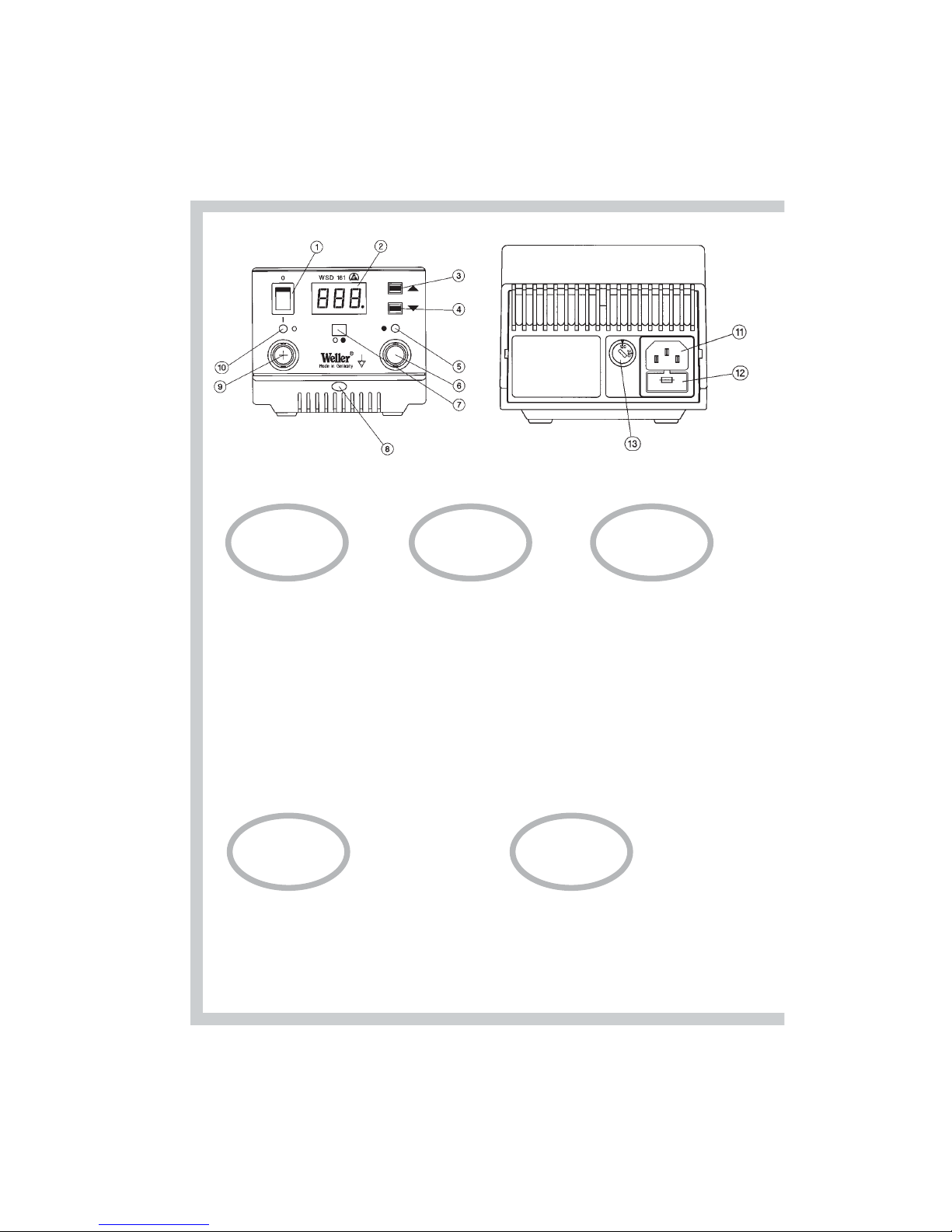
WSD 161
1. Netzschalter
2. Digitalanzeige
3. „Up“-Taste
4. „Down“-Taste
5. Optische Regelkontrolle und
Anzeige Kanalwahl rechts
6. Anschlußbuchse Lötkolben rechts
7. Kanalwahltaste
8. Potentialausgleichsbuchse
9. Anschlußbuchse Lötkolben links
10.Optische Regelkontrolle und
Anzeige Kanalwahl links
11.Netzanschluß
12.Netzsicherung
13.Spannungswahlschalter
(nur umschaltbare Version)
1. Interrupteur secteur
2. Afficheur numérique
3. Touche „Up“
4. Touche „Down“
5. Contrôle visuel du réglage et affi
chage de la sélection du canal de
droite
6. Prise de raccordement pour le fer
à souder de droite
7. Touche de sélection du canal
8. Prise d’équipotentialité
9. Prise de raccordement du fer à
souder de gauche
10.Contrôle visuel du réglage et affi
chage de la sélection du canal de
gauche
11.Connecteur secteur
12.Fusible secteur
13.Sélecteur de tension
(uniquement version commuta
ble)
1. Netschakelaar
2. Digitaal display
3. ”Up” toets
4. ”Down toets”
5. Optische regelcontrole en aanwij
zing
kanaalkeuze rechts
6. Aansluitbus soldeerbout rechts
7. Kanaalkeuzetoets
8. Potentiaalvereffeningsbus
9. Aansluitbus soldeerbout links
10.Optische regelcontrole en aanwij
zing
kanaalkeuze links
11.Netaansluiting
12.Netzekering
13.Spanningskeuzeschakelaar
(alleen omschakelbare versie)
1. Interruttore di rete
2. Indicatore digitale
3. Tasto „Up“
4. Tasto „Down“
5. Controllo di regolazione ottico e indicatore selezione
canale destro
6. Boccola di collegamento stilo brasatore destra
7. Tasto selezione canale
8. Boccola per la compensazione di potenziale
9. Boccola di collegamento stilo brasatore sinistra
10.Controllo di regolazione ottico e indicatore selezione
canale sinistro
11.Collegamento a rete
12.Fusibile di rete
13.Selettore tensione (solo nella versione commutabile)
1. Mains Switch
2. Digital Display
3. „Up“ Button
4. „Down“ Button
5. Right Hand Optical Regulator Monitor and Channel
Selection Indicator
6. Right Hand Soldering Iron Connector
7. Channel Selection Button
8. Potential Equalisation Connector (not USA )
9. Left Hand Soldering Iron Connector
10.Left Hand Optical Regulator Monitor and Channel
Selection Indicator
11.Mains Connection
12.Mains Fuse
13.Voltage Selection Switch
FIN
1. Virtakytkin
2. Digitaalinen näyttö
3. „UP“-näppäin
4. „DOWN“-näppäin
5. Optinen säätökontrolli ja
kanavan valintanäyttö oik.
6. Kolvin liitäntä oik.
7. Kanavan valintanäppäin
8. Potentiaalintasausliitäntä
9. Kolvin liitäntä vas.
10.Optinen säätökontrolli ja
kanavan valintanäyttö vas.
11.Verkkoliitäntä
12.Verkkosulake
13.Jännitteen valintakytkin
(vain vaihtomahdollisuuden
omaavissa laitteissa)
P
1. Interruptor geral
2. Mostrador digital
3. Botão „Up“
4. Botão „Down“
5. Controlo óptico de regulação e
indicador de selecção do canal
direito
6. Tomada para ligação do ferro de
soldar, lado direito
7. Botão de selecção do canal
8. Tomada da ligação equipotencial
9. Tomada para ligação do ferro de
soldar, lado esquerdo
10.Controlo óptico de regulação e
indicador de selecção do canal
esquerdo
11. Ligação à rede
12. Fusível de rede
13. Comutador-selector de tensão
(só versão comutável)
DK
1. Netafbryder
2. Digitalvisning
3. ”Up”-knap
4. ”Down”-knap
5. Optisk styringskontrol og visning
af kanalvalg til højre
6. Tilslutningsbøsning for
loddekolberne til højre
7. Kanalvalgsknap
8. Potentialudligningsbøsning
9. Tilslutningsbøsning for
loddekolberne til venstre
10.Optisk styringskontrol og
visning af kanalvalg til højre
11.Nettilslutning
12.Netsikring
13.Spændingsvalgkontakt (kun for
den omstillelige version)
ES
1. Nätströmbrytare
2. Digitalindikation
3. ”Up”-tangent
4. ”Down”-tangent
5. Optisk reglerkontroll och indika
tion, kanalval höger
6. Anslutningsbussning lödkolv
höger
7. Kanalvalstangent
8. Potentialutjämningsbussning
9. Anslutningsbussning lödkolv vän
ster
10.Optisk reglerkontroll och indika
tion, kanalval vänster
11.Nätanslutning
12.Nätsäkring
13.Spänningsväljaromkopplare
(endast omkopplingsbar version)
TR
GR
1. ∆ιακπτης ηλεκτρικού ρεύµατος
2. Ψηφιακή ένδειξη
3. Πλήκτρο ”Up”
4. Πλήκτρο ”Down”
5. Οπτικς έλεγχος και ένδειξη της
επιλογής καναλιού δεξιά
6. Υποδοχή σύνδεσης του εµβλου
συγκλλησης δεξιά
7. Πλήκτρο επιλογής καναλιού
8. Υποδοχή εξίσωσης δυναµικού
9. Υποδοχή σύνδεσης του εµβλου
συγκλλησης αριστερά
10. Οπτικς έλεγχος και ένδειξη της
επιλογής καναλιού αριστερά
11. Σύνδεση στο ηλεκτρικ δίκτυο
12. Ασφάλεια ηλεκτρικού δικτύου
13. ∆ιακπτης επιλογής της ηλεκτρικής
τάσης (µνο στην κατασκευαστική
παραλλαγή µε δυναττητα
µεταρρύθµισης)
1. Interruptor primario
2. Indicador digital
3. Tecla ”Up”
4. Tecla ”Down”
5. Control óptico de regulación e indi
cador de selección de canal a dercha
6. Conector hembra para la conexión
del soldador a derecha
7. Tecla para selección del canal
8. Conector hembra para la
compensación de potencial
9. Conector hembra para la conexión
del soldador a izquierda
10.Control óptico de regulación e indi
cador de selección de canal a izquierda
11.Toma de corriente
12.Fusible
13.Conmutador selector de tensión
(sólo en la versión conmutable)
CZ
1. SíÈov˘ vypínaã
2. Digitální displej
3. Tlaãítko Up
4. Tlaãítko Down
5. Optická kontrola regulace a indikátor volby pravého kanálu
6. Zásuvka pro pfiipojení pravého pájecího pera
7. Tlaãítko pro volbu kanálu
8. Zdífika pro vyrovnání potenciálÛ
9. Zásuvka pro pfiipojení levého pájecího pera
10. Optická kontrola regulace a indikátor volby levého kanálu
11. SíÈová pfiípojka
12. SíÈová pojistka
13. Pfiepínaã síÈového napûtí
(jen pfiepínatelná verze)
1. Elektrik ¸salteri
2. Dijital gösterge
3. „UP” (yukarı) tu¸su
4. „DOWN” (a¸sa˘gı) tu¸su
5. Ayarlar için optik kontrol ve sa˘g kanal seçimi
6. Lehim kalemi için sa˘g ba˘glantı giri¸si
7. Kanal seçim tu¸su
8. Potansiyel denkleme giri¸si
9. Lehim kalemi için sol ba˘glantı giri¸si
10.Ayarlar için optik kontrol ve sol kanal seçimi
11.Elektrik ba˘glantısı
12.Elektrik sigortası
13.Voltaj seçim ¸salteri (yalnız voltaj seçim ¸salteri olan
modellerde)
LV
LT
SLO
SKHPL
EST
1. W∏àcznik sieciowy
2. Wskaênik cyfrowy
3. Przycisk Up
4. Przycisk Down-
5. Optyczna kontrola regulacji oraz
wskaênik prawego kana∏u
6. Prawe gniazdo przy∏àczenio
we lutownicy
7. Przycisk wyboru kana∏u
8. Gniazdo wyrównania potenc ja∏u
9. Lewe gniazdo przy∏àczenio we
lutownicy
10.Optyczna kontrola regulacji
oraz wskaênik lewego kana∏u
11.Przy∏àcze sieciowe
12.Bezpiecznik sieciowy
13.Prze∏àcznik zmiany napi´cia
(tylko w wersji z prze∏àcznikiem)
1. Hálózati kapcsoló
2. Digitális kijelzŒ
3. Up-gomb
4. Down-gomb
5. Jobb optikai szabályozóellenŒrzŒ
és csatornaválasztás kijelzŒ
6. Jobb forrasztópáka csatlakozó
hüvely
7. Csatornaválasztó gomb
8. PotenciálkiegyenlítŒ hüvely
9. Bal forrasztópáka csatlakozóhü
vely
10.Bal optikai szabályozóellenŒrzŒ
és csatornaválasztás kijelzŒ
11.Hálózati csatlakozás
12.Hálózati biztosíték
13.Feszültségválasztó kapcsoló
(csak átkapcsolható változatnál)
1. SieÈov˘ vypínaã
2. Digitálny displej
3. Tlaãidlo Up
4. Tlaãidlo Down
5. Optická kontrolka regulácie a
ukazovateº voºby kanálu vpravo
6. Zásuvka pre spájkovaãku
vpravo
7. Tlaãidlo na voºbu kanálu
8. Zdierka pre vyrovnanie napä
tia
9. Zásuvka pre spájkovaãku
vºavo
10.Optická kontrolka regulácie a
ukazovateº voºby kanálu vºavo
11. SieÈová prípojka
12. SieÈová poistka
13. Prepínaã pre voºbu napätia
(len verzia s prepínaním)
1. OmreÏno stikalo
2. Digitalni prikaz
3. Tipka gor
4. Tipka dol
5. Vizualna kontrola regulacije in
prikaz izbranega kanala, desno
6. Prikljuãna doza za spajkalnik,
desna
7. Tipka za izbiro kanala
8. Pu‰a za izenaãevanje potenciala
9. Prikljuãna doza za spajkalnik,
leva
10.Vizualna kontrola regulacije in
prikaz izbranega kanala, levo
11.Vtiãnica za elektriãni kabel
12.OmreÏna varovalka
13.Stikalo za izbiro napetosti
(samo pri izvedbi z moÏnostjo
preklopa)
1. Võrgulüliti
2. Digitaalne ekraan
3. "Up"-klahv
4. "Down"-klahv
5. Optiline juhtimisindikaator ja
parempoolse kanalivaliku näidik
6. Parempoolne jootekolvi ühendu
spuks
7. Kanalivaliku nupp
8. Potentsiaalide ühtlustuspuks
9. Vasakpoolne jootekolvi ühendu
spuks
10.Optiline juhtimisindikaator ja
vasakpoolse kanalivaliku näidik
11.Võrguühendus
12.Võrgukaitse
13.Pingevaliku lüliti
(ainult ümberlülitav variant)
1. Tinklo jungiklis
2. Skaitmeninis indikatorius
3. Mygtukas „Up“
4. Mygtukas „Down“
5. Optinò valdymo kontrolò ir
kanal˜ pasirinkimo indikatorius
- de‰inò
6. Lituoklio prijungimo lizdas de‰inò
7. Kanal˜ pasirinkimo mygtukas
8. Potencial˜ i‰lyginimo lizdas
9. Lituoklio prijungimo lizdas kairò
10.Optinò valdymo kontrolò ir
kanal˜ pasirinkimo indikatorius
- kairò
11. Elektros tinklo prijungimo liz
das
12. Elektros tinklo saugiklis
13. Øtampos pasirinkimo jungiklis
(tik perjungiamajame modelyje)1. T¥kla slïdzis
2. DigitÇlais rÇd¥tÇjs
3. Tausti¿‰ "Ieslïgts"
4. Tausti¿‰ "Izslïgts"
5. OptiskÇ vad¥bas kontrole un rÇd¥tÇjs kanÇla izvïlei pa labi
6. Lodï‰anas virzu∫a pieslïguma bukse pa labi
7. KanÇla izvïles tausti¿‰
8. PotenciÇla l¥me¿o‰anas bukse
9. Pieslïguma bukse pa kreisi
10.OptiskÇ vad¥bas kontrole un rÇd¥tÇjs kanÇla izvïlei pa kreisi
11. T¥kla pieslïgums
12. T¥kla dro‰inÇtÇjs
13. Sprieguma izvïles slïdzis
(tikai pÇrslïdzamajiem mode∫iem)

D
F
NL
I
GB
S
E
FIN
P
DK
Inhaltsverzeichnis Seite
1. Achtung! 1
2. Beschreibung 1
Technische Daten 2
3. Inbetriebnahme 2
4. Potentialausgleich 3
5. Arbeitshinweise 3
6. Zubehörliste 3
7. Lieferumfang 3
Table des matières Page
1. Attention! 5
2. Description 5
Caractéristiques techniques 6
3. Mise en service 6
4. Equilibrage de potentiel 7
5. Instructions d‘emploi 7
6. Accessoires 7
7. Fournitures 7
Inhoud Pagina
1. Attentie! 9
2. Beschrijving 9
Technische gegevens 10
3. Ingebruikname 10
4. Potentiaal vereffening 11
5. Werkaanwijzingen 11
6. Toebehoren 11
7. Leveromvang 12
Indice Pagina
1. Attenzione! 13
2. Descrizione 13
Dati tecnici 13
3. Messa in funzione 14
4. Compensazione dei Potenziali 15
5. Indicazioni operative 15
6. Accessori 15
7. Volume di fornitura 16
Table of contents Page
1. Caution! 17
2. Description 17
Technical data 18
3. Commissioning 18
4. Equipotential bonding 18
5. Instructions for use 19
6. Accessories 19
7. Items supplied 19
Innehållsförteckning Sidan
1. Observera! 20
2. Beskrivning 20
Tekniska data 21
3. Idrifttagning 21
4. Potentialutjämning 21
5. Arbetsanvisningar 21
6. Tillbehör 22
7. Leveransomfång 22
Indice Página
1.¡Atención! 23
2.Descripción 23
Datos técnicos 24
3.Puesta en funcionamiento 24
4.Compensación de potencial 25
5.Indicaciones para el trabajo 25
6.Accesorios 25
7.Extensión del suministro 26
Indholdsfortegnelse Side
1. Forsigtig! 27
2. Beskrivelse 27
Tekniske data 28
3. Ibrugtagning 28
4. Potentialudligning 28
5. Arbejdshenvisninger 29
6. Ekstratilbehør 29
7. Med i leveringen 29
Índice Página
1. Atenção! 30
2. Descrição 30
Dados Técnicos 31
3. Colocação em funcionamento 31
4. Ligação equipotencial 32
5. Instruções de trabalho 32
6. Acessórios 32
7. Volume de entrega 33
Sisällysluettelo Sivu
1. Huomio! 34
2. Kuavaus 34
Tekniset tiedot 35
3. Käyttöönotto 35
4. Potentiaalintasaus 35
5. Työskentelyohjeita 36
6. Lisätarvikkeet 36
7. Toimituksen laajuus 36

SLO
TR
GR
CZ
PL
H
SK
LV
LT
EST
Obsah Strana
1. Pozor! 55
2. Popis 55
Technické údaje 56
3. Uvedenie do prevádzky 56
4. Vyrovnanie napätia 57
5. Pracovné pokyny 57
6. Zoznam príslu‰enstva 57
7. Rozsah dodávky 58
Vsebina Stran
1. Pozor! 59
2. Opis 59
Tehniãni podatki 60
3. Pred uporabo 60
4. Izenaãevanje potenciala 61
5. Navodila za delo 61
6. Seznam pribora 61
7. Obseg dobave 61
Sisukord Lehekülg
1. Tähelepanu! 63
2. Kirjeldus 63
Tehnilised andmed 64
3. Kasutuselevõtt 64
4. Potentsiaalide ühtlustamine 65
5. Tööjuhised 65
6. Lisavarustuse nimekiri 65
7. Tarne maht 65
Turinys Puslapis
1. Dòmesio! 67
2. Apra‰ymas 67
Techniniai duomenys 68
3. Pradedant naudoti 68
4. Potencial˜ i‰lyginimas 69
5. Darbo nurodymai 69
6. Papildomos ∞rangos sàra‰as 69
7. Tiekiamas komplektas 70
Satura rÇd¥tÇjs Lappuse
1. Uzman¥bu! 71
2. Apraksts 71
Tehniskie parametri 72
3. Darb¥bas uzsÇk‰ana 72
4. PotenciÇlu l¥me¿o‰ana 73
5. NorÇd¥jumi darbam 73
6. Piederumu uzskait¥jums 73
7. PiegÇdes apjomi 73
Πίνακας περιεχοµένων Σελίδα
1.
Προσοχή! 37
2. Περιγραφή 37
Τεχνικά χαρακτηριστικά 38
3. Αρχική θέση σε λειτουργία 38
4. Εξίσωση δυναµικού 39
5. Οδηγίες εργασίας 39
6. Συµπληρωµατικά εξαρτήµατα 40
7. Μέγεθος της παράδοσης 40
|˙çindekiler Sayfa
1. Dikkat! 41
2. Tasvir 41
Teknik veriler 41
3. Kullanıma alı¸s42
4. Potansiyel denkleme 42
5. Kullanımla ilgili notlar 42
6. Aksam listesi 43
7. Satı¸s kapsamı 43
Seznam Strana
1. Pozor! 44
2. Popis 44
Technické údaje 45
3. Uvedení do provozu 45
4. Vyrovnání potenciálÛ 45
5. Pracovní pokyny 46
6. Seznam pfiíslu‰enství 46
7. Rozsah dodávky 46
Spis treÊci Strona
1. Uwaga! 47
2. Opis 47
Dane techniczne 48
3. Uruchomienie 48
4. Wyrównanie potencja∏u 49
5. Wskazówki dot. pracy 49
6. Lista akcesoriów 50
7. Zakres wyposa˝enia 50
Tartalomjegyzék Oldal
1. Vigyázat! 51
2. Leírás 51
Mıszaki adatok 52
3. Üzembe helyezés 52
4. Potenciálkiegyenlítés 53
5. Útmutató a munkához 53
6. Tartozéklista 53
7. Szállítási terjedelem 53
WSD 161
WSL 2

1
Deutsch
Wir danken Ihnen für das mit dem Kauf der Weller Lötstation
WSD 161 / WSL 2 erwiesene Vertrauen. Bei der Fertigung
wurden strengste Qualitäts-Anforderungen zugrunde gelegt,
die eine einwandfreie Funktion des Gerätes sicherstellen.
1. Achtung!
Vor Inbetriebnahme des Gerätes lesen Sie bitte diese
Betriebsanleitung und die beiliegenden Sicherheitshinweise
aufmerksam durch. Bei Nichteinhaltung der Sicherheitsvorschriften droht Gefahr für Leib und Leben.
Für andere, von der Betriebsanleitung abweichende Verwendung, sowie bei eigenmächtiger Veränderung, wird von
Seiten des Herstellers keine Haftung übernommen.
Die Weller Lötstation WSD 161 / WSL 2 entspricht der EG
Konformitätserklärung gemäß den grundlegenden Sicherheitsanforderungen der Richtlinien 89/336/EWG und
73/23EWG.
2. Beschreibung
2.1 Steuergerät
Die Lötstation WSD 161 / WSL 2 gehört einer Gerätefamilie an, die für die industrielle Fertigungstechnik, sowie
für den Reparatur- und Laborbereich entwickelt wurde.
Einfache und komfortable Bedienung werden durch den
Einsatz eines Mikroprozessors ermöglicht. An zwei voneinander unabhängigen, digitalen Temperaturregelungen
können zwei unterschiedliche Lötwerkzeuge gleichzeitig
betrieben werden. Die Lötwerkzeuge selbst werden von
der Lötstation automatisch erkannt und die entsprechenden Regelparameter zugeordnet. Die besonders leistungsfähigen 24 V Heizelemente ermöglichen ein ausgezeichnetes, dynamisches Verhalten. Das Lötwerkzeug wird so
universell einsetzbar.
Verschiedene Potentialausgleichsmöglichkeiten zur Lötspitze, Nullspannungsschaltung, sowie antistatische
Ausführung von Steuergerät und Kolben, ergänzen den
hohen Qualitätsstandard. Die Anschlussmöglichkeit eines
externen Eingabegerätes erweitert die Funktionsvielfalt
dieser Lötstation. Mit den als Option erhältlichen
Eingabegeräte WCB 1 und WCB 2 können unter anderem
Zeit- und Verriegelungsfunktionen realisiert werden.
Integriertes Temperaturmeßgerät und PC-Schnittstelle
gehören zum erweiterten Umfang des Eingabegerätes
WCB 2.
Die gewünschte Temperatur kann im Bereich von 50°C 450°C (150°F - 850°F) über 2 Tasten (Up / Down) eingestellt werden. Soll- und Istwert werden durch die entsprechende Anwahl mit der Kanalwahltaste digital angezeigt.
Das Erreichen der vorgewählten Temperatur wird durch
eine, dem Kanal zugeordnete LED, signalisiert, die somit
als optische Regelkontrolle dient. Dauerndes Leuchten
bedeutet, dass das System aufheizt.
2.2 Lötkolben
LR 21: Unser „Standard“ Lötkolben. Mit einer
Leistung von 50 W und eine sehr breiten
Lötspitzenspektrum (ET-Serie) ist dieser
Lötkolben universell im Elektronikbereich
einsetzbar.
MLR 21: Mit seiner Leistung von 25 W und einer
schlanken Bauform eignet sich dieser
Mikro-Lötkolben besonders für feine
Lötarbeiten mit geringem Wärmebedarf.
MPR 80: Der Weller Peritronic MPR 80 ist ein
Lötkolben mit einstellbarem Arbeitswinkel
von 40°. Dadurch wird eine individuelle
Gestaltung des Lötprozesses hinsichtlich
seiner Ergonomie ermöglicht. Durch seine
Leistung von 80 W und schlanker Bauform
eignet er sich für feine Lötarbeiten.
WTA 50: Die Entlötpinzette WTA 50 wurde speziell
zum Auslöten von SMD-Bauteilen konzi
piert. Zwei Heizelemente (2 x 25 W) mit
jeweils eigenem Temperatursensor sorgen
für gleiche Temperaturen an beiden
Schenkeln.
LR 82: Leistungsfähiger 80 W Lötkolben für
Lötarbeiten mit großem Wärmebedarf. Die
Befestigung der Lötspitze erfolgt über
einen Bajonettverschluss, der einen positionstreuen Spitzenwechsel ermöglicht.
WSP 80: Der Lötkolben WSP 80 zeichnet sich durch
sein blitzschnelles und präzises Erreichen
der Löttemperatur aus. Durch seine
schlanke Bauform und einer Heizleistung
von 80 W ist ein universeller Einsatz von
extrem feinen Lötarbeiten bis hin zu sol
chen mit hohem Wärmebedarf möglich.
Nach Wechsel der Lötspitze ist ein
unmittelbares Weiterarbeiten möglich, da
die Betriebstemperatur in kürzester Zeit
wieder erreicht ist.
WSP 150: Besonders leistungsfähiger 150 W
Lötkolben für Lötarbeiten mit extrem
hohen Wärmebedarf. Bei der Verwendung
dieses Lötkolbens ist nur ein Kanal aktiv.
Erweiterter Temperaturbereich bis 550°C.
WMP: Der Weller Micro Lötkolben WMP eignet
sich durch sein handliches Konzept zur
Bearbeitung professioneller SMD
Elektronik. Eine kurze Distanz zwischen
Griffpunkt und Lötspitze erlaubt eine ergonomische Handhabung des 65 W Lötkolbens bei der Durchführung feinster

2
Deutsch
Lötaufgaben
Weiter anschließbare Werkzeuge siehe Zubehörliste.
Technische Daten (siehe auch Typenschild-
angabe)
Abmessungen in mm: 166 x 115 x 101 (L x B x H)
Netzspannung (11): 230 V / 50/60 Hz; 240/120V
/ 50/60 Hz; 100V / 50/60 Hz
Leistungsaufnahme: 150 W
Schutzklasse: 1 (Steuergerät) und 3
(Lötkolben)
Sicherung (12): T800 mA (230 V / 50/60 Hz)
(5 x 20 im Netzanschlusselement) T1,6 A (240/120V / 50/60Hz)
(umschaltbare Version)
(120 V / 6O Hz)
(100 V / 50/60 Hz)
Temperaturregelung: 50°C - 450°C (150°F -850°F)
Genauigkeit: ± 9°C
Potentialausgleich (8): Über eine 3,5 mm
Schaltklinkenbuchse
(Grundzustand hart geerdet)
3. Inbetriebnahme
Lötkolbenablage montieren (siehe Explo-Zeichnung). Zur
Montage der WMP Sicherheitsablage wird die mit
Gewindeeinsätzen ausgestattete Fußplatte verwendet.
Das Lötwerkzeug in der Sicherheitsablage ablegen.
Lötkolben-stecker in die Anschlußbuchsen (6) und (9)
des Steuer-gerätes einstecken und durch kurze
Rechtsdrehung arretieren. Überprüfen, ob die
Netzspannung mit der Angabe auf dem Typenschild übereinstimmt und der Netzschalter (1) sich im ausgeschaltenen Zustand befindet. Steuer-gerät mit dem Netz verbinden (11). Gerät am Netzschalter (1) einschalten. Beim
Einschalten des Gerätes wird ein Selbsttest durchgeführt,
bei dem alle Anzeigeelemente (2) in Betrieb sind.
Anschließend wird kurzzeitig die eingestellte Temperatur
(Sollwert) des aktivierten Kanals und die
Temperatur version (°C / °F) angezeigt. Danach schaltet
die Elektronik automatisch auf die Istwertanzeige um.
LED (5) bzw. (10) leuchtet. Diese Leuchtdioden dienen als
optische Regelkontrolle. Dauerndes Leuchten bedeutet
System heizt auf. Blinken signalisiert das Erreichen der
Betriebstemperatur.
Kanalwahl
Durch das Betätigen der Kanalwahltaste (7) kann die
Digitalanzeige auf den gewünschten Kanal 1 oder 2 eingestellt werden. Der jeweils angezeigte Kanal ist durch
eine rot / orange Leuchtdiode (5) oder (10) über der
Anschlußbuchse gekennzeichnet.
Der angezeigte Kanal kann durch gleichzeitiges Betätigen
der „Up“ und „Down“ Taste (3) (4) ausgeschalten werden. Dies wird in der Anzeige mit „Off“ bestätigt.
Zur Aktivierung eines ausgeschaltenen Kanals wird dieser gegebenenfalls durch die Kanalwahltaste ausgewählt
und durch gleichzeitiges Drücken der „Up“ und „Down“
Taste (3) (4) eingeschalten. In der Anzeige erscheint der
Istwert.
Temperatureinstellung
Grundsätzlich zeigt die Digitalanzeige (2) den
Temperaturistwert an. Durch Betätigen der „Up“ oder
„Down“ Taste (3) (4) schaltet die Digitalanzeige (2) auf
den derzeit eingestellten Sollwert um. Dieser (blinkende
Anzeige) kann nun durch Antippen oder permanentes
Drücken der „Up“ oder „Down“ Taste (3) (4) in entsprechender Richtung verändert werden. Wird die Taste permanent gedrückt, verändert sich der Sollwert im
Schnelldurchlauf. Ca. 2 sek. nach dem Loslassen schaltet die Digitalanzeige (2) automatisch wieder auf den
Istwert um.
Standardsetback
Herabsetzen der eingestellten Solltemperatur auf 150°C
(300°F). Die Setbackzeit, nachdem die Lötstation in den
Standbymodus wechselt beträgt 20 min. Nach dreifacher
Setbackzeit (60 min) wird die „Auto-off“ Funktion aktiviert. Das Lötwerkzeug wird abgeschalten (blinkender
Strich in der Anzeige).
Einstellung: Während des Einschaltens die „UP“ - Taste
(3) gedrückt halten bis ON oder OFF in der Anzeige
erscheint. Beim Loslassen der “UP” Taste wird die
Einstellung abgespeichert. Zum Verändern den Vorgang
wiederholen.
Die Setback-Funktion ist für beide Kanäle einstellbar.
Entscheidend ist der beim Ausschalten angezeigte Kanal.
Bei der Verwendung von sehr feinen Lötspitzen kann die
Zuverlässigkeit der Setback-Funktion beeinträchtigt sein.
Wartung
Der Übergang zwischen Heizkörper / Sensor und der
Lötspitze darf nicht durch Schmutz, Fremdkörper oder
Beschädigung beeinträchtigt werden, da dies Auswirkungen auf die Genauigkeit der Temperaturregelung hat.

4. Potentialausgleich
Durch die unterschiedliche Beschaltung der 3,5 mm
Schaltklinkenbuchse (8) sind 4 Variationen realisierbar:
Hart geerdet: Ohne Stecker (Auslieferungs-
zustand)
Potentialausgleich
(Impedanz 0 Ohm): Mit Stecker, Ausgleichsleitung am
Mittelkontakt
Potentialfrei: Mit Stecker
Weich geerdet: Mit Stecker und eingelötetem
Widerstand.
Erdung über den gewählten
Widerstandswert.
5. Arbeitshinweise
Beim ersten Aufheizen die selektive verzinnbare Lötspitze
mit Lot benetzen. Diese entfernt lagerbedingte Oxydschichten und Unreinheiten der Lötspitze. Bei Lötpausen
und vor dem Ablegen des Lötkolbens immer darauf achten, daß die Lötspitze gut verzinnt ist. Keine zu aggressiven Flußmittel verwenden.
Achtung: Immer auf ordnungsgemäßen Sitz der Lötspitze achten.
Die Lötgeräte wurden für eine mittlere Lötspitze justiert.
Abweichungen durch Spitzenwechsel oder der Verwendung von anderen Spitzenformen können entstehen.
Wird durch die angeschlossenen Lötwerkzeuge die
Gesamtleistung des Gerätes überschritten schaltet der
rechte Kanal automatisch ab.
Externes Eingabegerät WCB 1 und WCB 2 (Option)
Bei der Verwendung eines externen Eingabegerätes stehen folgende Funktionen zur Verfügung.
Offset: Die reale Lötspitzentemperatur kann durch
die Eingabe eines Temperaturoffsets um ±
40°C verändert werden.
Setback: Herabsetzung der eingestellten Solltem-
peratur auf 150°C (standby). Die Setbackzeit, nachdem die Lötstation in den Standbymodus wechselt, ist von 0-99 Minuten
einstellbar. Der Setbackzustand wird dur ch
eine blinkende Istwertanzeige signalisiert
und durch Drücken einer Taste oder
Fingerschalterdruck wieder beendet. Dabei
wird kurzzeitig der eingestellte Sollwert
angezeigt. Nach dreifacher Setbackzeit
wird die „AUTO OFF“ Funktion aktiviert.
Das Lötwerkzeug wird abgeschalten
(Blinkender Strich in der Anzeige).
Lock: Verriegelung der Solltemperatur. Nach der
Verriegelung sind an der Lötstation keine
Einstellungsänderungen möglich.
°C/°F: Umschalten der Temperaturanzeige von °C
in °F und umgekehrt. Drücken der „Down“
Taste während des Einschaltens zeigt die
aktuelle Temperaturversion an.
Window: Einschränkung des Temperaturbereichs
auf max. ± 99°C ausgehend von einer
durch die „LOCK“ Funktion verriegelten
Temperatur. Die verriegelte Temperatur
stellt somit die Mitte des einstellbaren
Temperaturbereiches dar.
Cal: Neujustierung der Lötstation (nur WCB2)
und Factory setting FSE (Rücksetzen aller
Einstellwerte auf 0, Temperatursollwert
350°C / 660°F).
6. Zubehörliste
5 29 161 99 Lötkolbenset WSP 80
5 33 131 99 Lötkolbenset MPR 80
5 33 111 99 Lötkolbenset MLR 21
5 33 112 99 Lötkolbenset LR 21 antistatisch
5 33 113 99 Lötkolbenset LR 82
5 33 155 99 Lötkolbenset WMP
5 33 133 99 Entlötset WTA 50
5 13 050 99 Reflow-Lötgerät EXIN 5
5 25 030 99 Thermisches Abisoliergerät WST 20
5 31 181 99 Externes Eingabegerät WCB 1
5 31 180 99 Externes Eingabegerät WCB 2
WPHT Schaltablage (WMP)
WPH80T Schaltablage (WSP 80)
7. Lieferumfang
WSD 161
PUD 161 Steuergerät
2 x WSP 80 Lötkolben
2 x WPH 80 Lötkolbenablage
Netzkabel
Klinkenstecker
Bedienungsanleitung
Sicherheitshinweise
3
Deutsch

4
WSL 2
PUD 161 Steuergerät
1 x WSP 80 Lötkolben
1 x WPH 80 Lötkolbenablage
1 x WMP Lötkolben
1 x WPHM Lötkolbenablage
Netzkabel
Kinkenstecker
Bedienungsanleitung
Sicherheitshinweise
PUD 161
PUD 161 Steuergerät
Netzkabel
Klinkenstecker
Bedienungsanleitung
Sicherheitshinweise
Bild Schaltplan siehe Seite 75
Bild Explo-Zeichnung siehe Seite 76/77
Technische Änderungen vorbehalten!
Deutsch

Nous vous remercions de la confiance que vous nous
avez accordée en achetant le support de la station de soudage WSD 161 / WSL 2 de Weller. Lors de la fabrication,
des exigences de qualité très sévères assurant un fonctionnement parfait de l’appareil, ont été appliquées.
1. Attention!
Avant la mise en service de l’appareil, veuillez lire attentivement ce mode d’emploi et les consignes de sécurité cijointes. Dans le cas du non-respect des consignes de
sécurité, il y a danger pour le corps et danger de mort.
Le fabricant décline toute responsabilité pour les utilisations autres que celles décrites dans le mode d’emploi de
même que pour les modifications effectuées par l’utilisateur.
Le support de la station de soudage WSD 161 / WSL 2 de
Weller correspond à la déclaration de conformité européenne en application des exigences de sécurité fondamentales de la directive 89/336/CEE et 73/23/CEE.
2. Description
2.1 Appareil de commande
La station de soudage WSD 161 / WSL 2 fait partie d’une
série d’appareils développée pour la fabrication industrielle ainsi que pour la réparation et le laboratoire. Le recours
à un microprocesseur garantit un emploi simple et agréable. Deux régulateurs de température numériques séparés
permettent d’utiliser simultanément deux outils de soudage différents. La station de soudage reconnaît automatiquement les outils de soudage et leur attribue les paramètres de réglage correspondants. Les éléments chauffants de 24 V, particulièrement performants, possèdent
d’excellentes caractéristiques dynamiques et contribuent
à l’universalité d’emploi de l’outil de soudage.
Différentes possibilités de compensation du potentiel avec
la panne, un commutateur à tension nulle de même que
l’exécution antistatique de l’appareil de commande et du
fer à souder témoignent du niveau de qualité atteint et la
possibilité de raccorder un appareil d’entrée externe
accroît encore la polyvalence de cette station de soudage.
Les appareils d’entrée WCB 1 et WCB 2, disponibles en
option, permettent entre autres de réaliser des fonctions
chronologiques et de verrouillage. Un contrôleur de température intégré et une interface pour PC complètent l’appareil d’entrée WCB 2.
La température souhaitée peut être réglée dans une plage
de 50°C à 450°C (150°F à 850°F) à l’aide de 2 touches
(Up/Down). La valeur de consigne et la valeur réelle sont
affichées numériquement après avoir effectué la sélection
correspondante avec la touche de sélection du canal.
Lorsque la température présélectionnée est atteinte, une
LED de contrôle visuel du réglage, attribuée au canal correspondant, le signale. Cette LED est allumée en permanence pendant que le système chauffe.
2.2 Fer à souder
LR 21: Notre fer à souder "standard". Avec une
puissance de 50 watts et unelarge gamme
de pannes (série ET), ce fer à souder est
d'une utilisationuniverselle dans le domai
ne de l'électronique.
MLR 21: Avec sa puissance de 25 watts et sa forme
éfilée, ce micro fer à souder convient plus
particulièrement aux travaux de soudage
nécessitant une faible source de chaleur.
MPR 80: Le Weller Peritronic MPR 80 dont on peut
modifier l‘angle de travail jusqu‘à 40° per
met d‘individualiser le processus de souda
ge au plan de l'ergonomie. Avec sa puis
sance de 80 watts et sa forme éfilée, ce fer
convient pour les travaux de soudage de
précision.
WTA 50: La pince à dessouder WTA 50 a été spéci
alement conçus pour dessouder les com
posants montés en surface. Deux élé
ments chauffants (2 x 25 watts) équipés
chacun de leur propre sonde assurent une
même température aux deux extrémités de
la pince.
LR 82: Un puissant fer à souder de 80 watts pour
les travaux nécessitant une source de cha
leur importante. La fixtion de la panne est
assurée par un système à baïonnette gar
antissanun parfait positionnement de la
panne en cas de remplacement de celleci.
WSP 80: Le fer à souder WSP 80 se distingue par la
grande rapidité et la précision avec les
quelles il atteint la température de souda
ge. Grâce à sa forme éfilée et à sa puis
sance de 80 W, son utilisation est univer
selle et va des travaux de soudage de très
grande précision à ceux requérant une
source de chaleur importante. Après un
changement de panne, il est possible de
continuer de travailler sans interruption
dans la mesure ou la température de ser
vice est atteinte très rapidement.
WSP 150: Fer à souder particulièrement performant
de 150W pour les travaux de soudage exi
geant une chaleur très importante. Un seul
canal est actif lorsque ce fer à souder est
utilisé. Plage de température élargie jusqu
’à 550°C.
WMP: Avec son concept de maniabilité, le micro
5
Français

6
fer à souder Weller WMP convient pour le
travail avec les composants électroniques
professionnels montés en surface (SMD).
Une courte distance entre le point de saisie et la panne de soudage permet une
manipulation ergonomique du 65 W fer à
souder lors de la réalisation des travaux de
soudage les plus délicats.
Pour les autres outils pouvant être raccordés, voir la
liste des accessoires.
Caractéristiques techniques (voir également l’indica
tion à la plaque signalé
tique)
Dimensions en mm: 166 x 115 x 101 (lxpxh)
Tension d’alimentation (11): 230 V / 50/60 Hz;
240/120V / 50/60 Hz;
100V / 50/60 Hz
Puissance absorbée: 150 W
Classe de protection: 1 (appareil de comman
de) et 3 (fer à souder)
Fusible (12): T800mA (230V/50/60Hz)
(5x20 dans l’élément de
raccordement secteur) T1,6A
(240/120V/50/60Hz)
(pour les version bitensions)
(120 V / 60 Hz)
(100 V / 50/60 Hz)
Régulation de température: 50°C - 450°C
(150°F - 850°F)
Précision: ± 9°C
Compensation du potentiel (8): Par une prise jack de
3,5 mm
(mise à la terre dure d’o
rigine)
3. Mise en service
Assembler le support de fer à souder (voir la vue éclatée). Pour le montage du support de sécurité WMP, utiliser la plaque d'assise munie de douilles taraudées.
Placer l’outil de soudage dans le support de sécurité.
Brancher les fiches de fer à souder sur les prises de raccordement (6) et (9) de l’appareil de commande et les
verrouiller par une courte rotation à droite. Vérifier si la
tension du secteur correspond à la tension indiquée sur
la plaque signalétique et si l’interrupteur secteur (1) est
coupé. Brancher l’appareil de commande sur le secteur
(11). Mettre l’appareil en marche par l’interrupteur secteur (1). Lors de la mise en marche de l’appareil, celui-ci
effectue un auto-test au cours duquel tous les éléments
d’affichage (2) fonctionnent. La température réglée
(valeur de consigne) du canal activé et la version (°C/°F)
est ensuite brièvement indiquée, après quoi l’électronique commute automatiquement l’affichage de la valeur
réelle. La LED (5) ou (10) est allumée. Ces diodes électroluminescentes servent au contrôle visuel du réglage.
Elles sont allumées en permanence pour indiquer que le
système est en chauffe et clignotent pour signaler que la
température de service est atteinte.
Sélection du canal
En actionnant la touche de sélection du canal (7), l’affichage numérique peut être réglé sur le canal 1 ou 2 souhaité. Le canal affiché est signalé par une diode électroluminescente rouge/orange (5) ou (10) qui se trouve audessus de la prise de raccordement .
Le canal affiché peut être désactivé en appuyant simultanément sur les touches „Up“ et „Down“ (3) (4), ce que
confirme l’indication „OFF“ sur l’afficheur.
Pour activer un canal désactivé, sélectionner le cas échéant une nouvelle fois celui-ci avec la touche de sélection
et appuyer simultanément sur la touche „Up“ et „Down“
(3) (4). La valeur réelle apparaît sur l’afficheur.
Réglage de la température
L'afficheur numérique (2) indique la température réelle.
En actionnant les touches "Up" ou "Down" (3) (4), l'afficheur numérique (2) indique momentanément la valeur
de consignes réglée. Cette valeur peut alors être modifiée dans la direction voulue en appuyant par intermittence ou de façon prolongée sur les touches "Up" ou "Down"
(3) (4). Lorsque les touches sont enfoncées de façon
prolongées, la valeur de consigne change rapidement.
Environ 2 secondes après avoir relâché les touches, l'afficheur numérique (2) indique automatiquement la valeur
réelle.
Mise enveille:
Réduction de la température de consigne à 150°C
(300°F). Le temps de réduction au bout duquel la station
de soudage se met en stand-by est de 20 mn. Après trois
fois le temps de réduction (60 mn), la fonction ”Autooff” est activée. L’outil de soudage est mis à l’arrêt (trait
clignotant sur l’afficheur).
Réglage: Pendant la mise en marche, maintenir la touche
”UP” (3) enfoncée jusqu’à ce que l’afficheur indique ON
ou OFF. Le relâchement de la touche "UP" entraîne l’enregistrement du réglage. Répéter cette opération pour
modifier.
La fonction Setback est réglable pour les deux canaux.
Le canal affiché lors de l'extinction est déterminant. La
fiabilité de la fonction Setback peut être altérée si des
pannes très fines sont utilisées.
Français

Entretien
La jonction entre l'élément chauffant/sonde de la panne
ne doit pas être altérée par des saletés, des corps étrangers ou des endommagée ou être endommagée car ceci
se répercute sur la précision de la régulation de température.
4. Compensation du potentiel
4 variantes d‘equilibrage de potentiel peuvent être réalisées suivant le branchement de la prise jack de 3,5 mm
(8):
Mise à la terre directe: Pas de fiche (état d'origine).
Equilibrage de potentiel
(impédance 0 ohm): Avec fiche, reliée au contact
central.
Libre de potentiel: Avec fiche
Mise à la terre indirecte: Avec fiche et résistance sou
dée. Mise à la terre par l'in
termédiaire de la valeur de la
résistance choisie.
5. Instructions d'emploi
A la première mise en température, étamer la panne avec
la soudure appropriée. Ceci supprime les couches d'oxyde et les impuretés présentes sur la panne suite au stokkage. Au cours des pauses de travail et avant de reposer
le fer à souder, s'assurer toujours que la panne soit bien
étamée. Ne pas utiliser de flux trop agressif.
Attention: Toujours s'assurer de la bonne fixation de la
panne.
Les appareils de soudage ont été réglés en fonction d'une
panne moyenne. Des différences sont donc possibles en
cas de changement de panne ou en cas d'utilisation de
pannes de forme différente.
Si la puissance des appareils de soudage raccordés est
supérieure à la puissance totale de l’appareil, le canal de
droite est automatiquement désactivé.
Programmateurs WCB 1 et WCB 2 (option)
Les fonctions ci-après sont disponibles si un programmateur est utilisé:
Offset: La température réelle de la panne peut
être modifiée de ± 40°C en entrant un
offset de température.
Setback: Réduction de la température de consig
ne réglée à 150°C (Standby). Le temps
de Setback au bout duquel la station de
soudage passe dans le mode Standby
peut être réglée de 0 à 99 minutes.
Après trois fois la durée de Setback, la
fonction ”Auto off” est activée. L ’outil de
soudage est déconnecté (trait clignotant
sur l’afficheur).
Lock: Vérrouillage de la température de con
signe. Après le vérrouillage
°C/°F: Sélection de l'affichage de la températu
re en °C ou en °F.
Window: Limitation de la plage de température à
±99°C maxi. à partir d'une température
verrouillée avec la fonction "LOCK". La
température verrouillée représente alors
le milieu de la plage de température
réglable.
Cal: Requalibrage de la station de soudage
(uniquement WCB 2).
6. Accessoires
5 29 161 99 Kit fer à souder WSP 80
5 33 131 99 Kit fer à souder MPR 80
5 33 111 99 Kit fer à souder MLR 21
5 33 112 99 Kit fer à souder LR 21
antistatique
5 33 113 99 Kit fer à souder LR 82
5 33 155 99 Kit fer à souder WMP
5 33 133 99 Kit de dessoudage WTA 50
5 13 050 99 Appareil de soudage par
refusion EXIN 5
5 25 030 99 Appareil à dénuder thermique
WST 20
5 31 181 99 Programmateur externe WCB 1
5 31 180 99 Programmateur externe WCB 2
WPHT Plaque reposoir commutatrice
(WMP)
WPH80T Plaque reposoir commutatrice
(WSP 80)
7
Français

8
7. Fournitures
WSD 161
Appareil de commande PUD 161
2 x Fer à souder WSP 80
2 x Support de fer à souder WPH 80
Câble secteur
Mode d’emploi
Fiche jack
Consignes de sécurité
WSL 2
Appareil de commande PUD 161
1 x Fer à souder WSP 80
1 x Support de fer à souder WPH 80
1 x Fer à souder WMP
1 x Support de fer à souder WPHM
Câble secteur
Mode d’emploi
Fiche jack
Consignes de sécurité
PUD 161
Appareil de commande PUD 161
Câble secteur
Mode d’emploi
Fiche jack
Consignes de sécurité
Figure schéma électrique voir la page 75
Figure vue éclatée voir la page 76/77
Sous réserve de modifications techniques!
Français

We danken u voor de aankoop van de Weller-soldeerstation WSD 161 / WSL 2 en het door u gestelde vertrouwen
in ons product. Bij de productie werd aan de strengste
kwaliteitsvereisten voldaan om een perfecte werking van
het toestel te garanderen.
1. Attentie!
Gelieve voor de ingebruikneming van het toestel deze
gebruiksaanwijzing en de bijgeleverde veiligheidsvoorschriften aandachtig door te nemen. Bij het niet naleven
van de veiligheidsvoorschriften dreigt gevaar voor leven
en goed.
Voor ander , van de gebruiksaanwijzing afwijkend gebruik,
alsook bij eigenmachtige verandering, wordt door de
fabrikant geen aansprakelijkheid overgenomen.
De Weller soldeerstation WSD 161 / WSL 2 is conform de
EG-conformiteitsverklaring volgens de fundamentele veiligheidsvereisten van de richtlijnen 89/336/EEG en
73/23EEG.
2. Beschrijving
2.1 Besturingsapparaat
Het soldeerstation WSD 161 / WSL 2 behoort tot een
familie van apparaten die voor de industriële productietechniek alsmede voor reparatie-bedrijven en laboratoria
ontwikkeld is. Een microprocessor zorgt voor een simpele en comfortabele bediening. Aan twee van elkaar onafhankelijke, digitale temperatuurregelaars kunnen twee
verschillende soldeerapparaten tegelijkertijd gebruikt
worden. De soldeerapparaten zelf worden door het soldeerstation automatisch herkend en krijgen de betreffende regelparameters. Door de zeer krachtige 24 V verwarmingselementen is een bijzonder dynamisch gedrag
mogelijk waardoor het soldeerapparaat universeel gebruikt kan worden.
Diverse potentiaalvereffeningsmogelijkheden voor soldeerpunt, nulspannings-schakelaar, de antistatische uitvoering van regelapparaat en bout verhogen de hoge
kwaliteitsstandaard. De mogelijkheid een extern invoerapparaat aan te sluiten vergroot het aantal functies van
dit soldeerstation. Met de als optie te verkrijgen invoerapparaten WCB 1 en WCB 2 kunnen onder andere tijd- en
vergrendelfuncties gerealiseerd worden. Een geïntegreerd temperatuurmeetapparaat en PC-interface behoren ook tot de omvangrijke levering van het invoerapparaat WCB 2.
De gewenste temperatuur kan tussen 50°C - 450°C
(150°F - 850°F) via 2 toetsen (up/down) ingesteld worden. Gewenste en werkelijke waarde worden door de
betreffende keuze met de kanaalkeuzetoets digitaal aangegeven. Als de gekozen temperatuur bereikt is, wordt
dat aangegeven via het knipperen van een aan het kanaal
toebedeelde LED, die zo als optische regelcontrole dient.
Als het lichtje voortdurend brandt, betekent dat dat het
systeem opgewarmd wordt.
2.2 Soldeerbouten
LR 21: Onze ”standaard” soldeerbout. Met een
vermogen van 50 W en een zeer breed sol
deerpuntspectrum (ET-serie) is deze sol
deerbout overal in de electronica te gebru
iken.
MLR 21: Met een vermogen van 25 W en een slan
ke vorm is deze micro-soldeerbout zeer
geschikt voor fijn soldeerwerk waarbij wei
nig warmte nodig is.
MPR 80: De Weller Pesitronic MPR 90 is een sol
deerbout met een instelbare werkhoek van
40°. Daardoor is een individuele vormge
ving van het soldeerproces ten aanzien van
zijn ergonomie mogelijk. Met een vermo
gen van 80 W en zijn slanke vorm is hij
zeer geschikt voor fijn soldeerwerk.
WTA 50: De soldeerruimpincet WTA 50 is speciaal
voor het solderen van SMD-onderdelen
geconcipieerd. Twee verwarmingselemen
ten (2 x 25 W) met ieder een eigent empe
ratuursensor zorgen voor een gelijke tem
peratuur aan beide benen.
LR 82: Een krachtig 80 W soldeerapparaat voor
soldeerwerk waarbij een hoge temperatuur
nodig is. Het bevestigen van de soldeer
punt gaat via een bajonetsluiting waardoor
het verwisselen van de punt op exact de
juiste plaats geschiedt.
WSP 80: Het soldeerapparaat WSP 80 onderscheidt
zich doordat de soldeertemperatuur
razendsnel en exact bereikt wordt. Door
zijn slanke vorm en een verhittingsvermo
gen van 80 W kan hij universeel gebruikt
worden, van extreem fijn soldeerwerk tot
soldeerwerk met zeer hoge temperaturen.
Na het wisselen van de soldeerpunt kan
direct verder gewerkt worden omdat de
bedrijfstemperatuur zeer snel weer bereikt
is.
WSP 150: Bijzonder krachtige 150W soldeerbout
voor soldeerwerkzaamheden met extreem
hoge warmtebehoefte. Bij het gebruik van
deze soldeerbout is slechts één kanaal
actief. Uitgebreid temperatuurbereik tot
550°C.
WMP: De Weller Micro soldeerbout WMP is door
zijn handzaam concept uitermate geschikt
9
Nederlands

10
voor het bewerken van professionele SMD
elektronica. Een korte afstand tussen
handgreep en soldeerpunt maakt een
ergonomisch gebruik van de 65 W soldeerbout tijdens het fijnste soldeerwerk
mogelijk.
Zie voor verdere, aan te sluiten apparatuur de lijst
met toebehoren.
Technische gegevens (zie ook gegevens op het
typeaanduidingplaat)
Afmetingen in mm 166 x 115 x 101 (l x b x h)
Netspanning(11): 230 V / 50/60 Hz; 240/120V
/ 50/60 Hz; 100V / 50/60 Hz
Krachtontneming: 150 W
Beschermklasse: 1 (besturingsapparaat) en 3
(soldeerapparaat)
Beveiliging (12): T800 mA (230 V / 50/60 Hz)
(5 x 20 in netaansluitele
ment) T1,6 A (240/120 V /
50/60 Hz)
(omschakelbare versie)
(120 V / 60 Hz)
(100 V / 50/60 Hz)
Temperatuurregeling: 50°C - 450°C (150°F -
850°F)
Precisie: ± 9°C
Potentiaalvereffening (8): via een 3,5 mm schakelklik
bus (basistoestand hard
geaard)
3. Ingebruikname
Soldeerkast monteren (zie Explo-tekening). Voor de
montage van het WMP-veiligheidsvak wordt de met
schroefdraadelementen uitgeruste voetplaat gebruikt.
Het soldeerapparaat in het veiligheidskastje leggen.
Stekker soldeerapparaat in de aansluitbus (6) en (9) van
het besturingsapparaat steken en vastzetten door een
slag naar rechts te draaien. Controleer of de netspanning
met die op het typeschildje overeenstemt en de netschakelaar (1) uitgeschakeld staat. Besturingsapparaat met
het electriciteitsnet verbinden (11). Apparaat via netschakelaar (1) inschakelen. Als het apparaat aangezet
wordt, wordt een zelftest uitgevoerd waarbij alle displayelementen (2) kort werken. Daarna wordt kort de ingestelde temperatuur (gewenste waarde) van het geactiveerde kanaal en de temperatuurversie (°C/°F) getoond.
Daarna schakelt de electronica automatisch op de werkelijke waarde om. LED (5) c.q. (10) lichten op. Deze lichtdiodes dienen als optische regelcontrole. Als ze continue
branden, betekent dat dat het systeem opgewarmd
wordt. Knipperen betekent dat de bedrijfstemperatuur is
bereikt.
Kanaalkeuze
Door de kanaalkeuzetoets (7) in te drukken kan het digitale display op het gewenste kanaal 1 of 2 ingesteld worden. Het op dat moment getoonde kanaal wordt door een
rood/oranje lichtdiode (5) of (10) boven de aansluitbus
aangegeven.
Het aangegeven kanaal kan uitgeschakeld worden door
tegelijkertijd de ”Up” en ”Down” (3) (4) toetsen in te
drukken. Dit wordt op het display met ”Off” bevestigd.
Kies voor het activeren van uitgeschakeld kanaal het
betreffende kanaal door de kanaalkeuzetoets te gebruiken en door tegelijkertijd de de ”Up” en ”Down” (3) (4)
toetsen in te drukken. Op het display verschijnt de werkelijke waarde.
Instellen temperatuur
In principe geeft het digitale display (2) de temperatuurwaarde aan. Door de knop ”Up” of ”Down” (3) (4) in te
drukken wordt het digitaaldisplay op de betreffende
gewenste waarde gezet. De ingestelde, gewenste waarde
kan alleen door het aanraken of permanent indrukken van
de ”Up” of ”Down” toetsen (3) (4) in de betreffende richting veranderd worden. Als de toets permanent ingedrukt
wordt, verandert de gewenste waarde in snel tempo. Ca.
2 seconden na het loslaten wordt het display (2) automatisch weer op de werkelijke waarde omgeschakeld.
Standaardsetback:
Verlagen van de ingestelde, gewenste temperatuur op
150°C (300°F). De setbacktijd bedraagt 20 minuten
nadat het soldeerstation in de standbymodus is gegaan.
Na drievoudige setbacktijd (60 min) wordt de ”auto-off”
functie geactiveerd. Het soldeergereedschap wordt uitgeschakeld (knipperende streep op het display).
Instelling: houd tijdens het inschakelen de ”UP”-toets (3)
ingedrukt tot ON of OFF op het display verschijnt. Bij het
loslaten van de "UP"-toets wordt de instelling opgeslagen.Herhaal procedure voor wijzigingen.
De setbackfunctie kan voor beide kanalen ingesteld
worden. Doorslaggevend is het bij het uitschakelen aangegeven kanaal. Bij gebruik van zeer fijne soldeerstiften
kan de betrouwbaarheid van de setbackfunctie beïnvloed worden.
Onderhoud
De overgang tussen verwarmingselement / sensor en de
soldeerpunt mag niet door vuil, vreemde stoffen of
beschadigingen belemmerd worden, omdat dit invloed
heeft op de nauwkeurigheid van de temperatuurregeling.
Nederlands

4. Potentiaalvereffening
Door de diverse soorten bedrading van de 3,5 mm
schakelklikbus (8) zijn 4 variaties mogelijk:
hard geaard: zonder stekker (positie af
fabriek)
potentiaalcompensatie
impedantie 0 Ohm): met stekker, compensaties
noer aan middelste contact
potentiaalvrij: met stekker
zacht geaard: met stekker en vastgesolde
erde weerstand Aarde via de
gekozen weerstandswaarde.
5. Werkaanwijzingen
Als het apparaat voor de eerste keer verwarmd wordt de
selectief te vertinnen soldeerpunt met soldeertin bevochtigen. Hierdoor worden door het opslaan veroorzaakte
oxydatielagen en verontreinigingen van de soldeerpunt
verwijderd. Tussen het solderen en voordat het soldeerapparaat wordt weggelegd er altijd op letten dat de soldeerpunt goed vertind is. Geen agressieve vloeibare middelen gebruiken.
Attentie: er altijd op letten dat de soldeerpunt juist
aangebracht is.
De soldeerapparaten zijn voor een gemiddelde soldeerpunt uitgelijnd. Er kunnen afwijkingen ontstaan door het
verwisselen van punten of het gebruik van andere puntvormen.
Als door de aangesloten soldeergereedschappen de totale capaciteit van het apparaat wordt overschreden, schakelt het rechter kanaal automatisch uit.
Extern invoerapparaat WCB 1 en WCB 2 (optie)
Bij gebruik van een extern invoerapparaat zijn de volgende functies beschikbaar.
Offset.: De reële temperatuur van de soldeer
punt kan door de invoer van een tempe
ratuuroffset met ± 40°C veranderd wor
den.
Setback: Terugzetten van de ingestelde gewenste
temperatuur op 150°C (stand-by).
Nadat het soldeerstation in de stand-by
modus is gezet kan de setbacktijd van 0
- 99 minuten ingesteld worden. Nadat
drie keer de setbacktijd is geactiveerd,
wordt ”Auto-Off“ geactiveerd. Het sol
deerapparaat wordt uitgeschakel (knip
perende streep op het display).
Lock: Vergrendeling van de gewenste tempe
ratuur. Na het vergrendelen kan op het
soldeerstation de instelling niet meer
veranderd worden. Aarde via de geko
zen weerstandswaarde.
°C/°F: Omschakelen van de temperatuuraan
wijzing van °C naar °F en omgekeerd.
Window: Beperking van het temperatuurbereik
tot max. ± 99°C uitgaande van een door
de "LOCK" functie vergrendelde tempe
ratuur. De vergrendelde temperatuur
vormt daardoor het middenpunt van het
instelbare temperatuurbereik.
Cal: Opnieuw uitlijnen van het soldeerstation
(alleen WCB 2)
6. Toebehoren
5 29 161 99 Soldeerset WSP 80
5 33 131 99 Soldeerset MPR 80
5 33 111 99 Soldeerset MLR 21
5 33 112 99 Soldeerset LR 21 antistatisch
5 33 113 99 Soldeerset LR 82
5 33 155 99 Soldeerset WMP
5 33 133 99 Soldeerruimset WTA 50
5 13 050 99 Reflow soldeerapparaat EXIN 5
5 25 030 99 Thermisch isoleerapparaat WST 20
5 31 181 99 Extern invoerapparaat WCB 1
5 31 180 99 Extern invoerapparaat WCB 2
WPHT Soldeerbouthouder met contactscha
kelaar (WMP)
WPH80T Soldeerbouthouder met contactscha
kelaar (WSP 80)
11
Nederlands

12
7. Leveromvang
WSD 161
PUD 161 besturingsapparaat
2 x WSP 80 soldeerapparaat
2 x WHP 80 soldeerapparaatkastje
Netkabel
Gebruiksaanwijzing
Stekker
Veiligheidsinstructies
WSL 2
PUD 161 besturingsapparaat
1 x WSP 80 soldeerapparaat
1 x WHP 80 soldeerapparaatkastje
1 x WMP soldeerapparaat
1 x WPHM soldeerapparaatkastje
Netkabel
Gebruiksaanwijzing
Stekker
Veiligheidsinstructies
PUD 161
PUD 161 besturingsapparaat
Netkabel
Gebruiksaanwijzing
Stekker
Veiligheidsinstructies
Afbeelding schakelschema zie pagina 75
Afbeelding Explo-tekening zie pagina 76/77
Technische wijzigingen voorbehouden!
Nederlands

Grazie per la fiducia accordataci acquistando la stazione
Weller di brasatura WSD 161 / WSL 2. È stato prodotto
nel rispetto dei più severi requisiti di qualità, così da garantire un funzionamento perfetto dell’apparecchio.
1. Attenzione!
Prima di mettere in funzione l’apparecchio, leggere accuratamente queste Istruzioni per l’uso e le Norme di sicurezza allegate. La mancata osservanza delle norme di
sicurezza può causare pericolo per la vita e la salute.
Il costruttore non è responsabile per un uso dell’apparecchio diverso da quello previsto nelle presenti
Istruzioni per l’uso né per eventuali modifiche non autorizzate.
La stazione Weller di brasatura WSD 161 / WSL 2 corrisponde alla Dichiarazione di conformità CE, ai sensi dei
requisiti fondamentali per la sicurezza delle direttive
89/336/CEE e 73/23CEE.
2. Descrizione
2.1 Stazione di controllo
La stazione di brasatura WSD 161 / WSL 2 fa parte di una
familia di apparecchi sviluppata per applicazioni industriali cos”ccome per il settore riparazione e laboratorio.
L’uso semplice e confortevole viene realizzato mediante
l’impiego di un microprocessore. Su di essa è possibile
utilizzare contemporaneamente due differenti utensili di
brasatura collegati a due circuiti digitali di regolazione
temperatura indipendenti fra di loro. I brasatori di per sè
vengono riconosciuti da parte della stazione di brasatura
e abbinati ai relativi parametri di regolazione in maniera
automatica. Le termoresistenze da 24 Volt particolarmente potenti permettono di ottenere un comportamento
eccezionalmente dinamico. In tale maniera gli utensili di
brasatura possono essere applicati universalmente.
L’alto standard qualitativo viene completato da differenti
possibilità di compensazione del potenziale verso la
punta di brasatura, grazie all’interruttore di tensione zero,
cos”ccome grazie all’esecuzione antistatica della cassetta di controllo e dello stilo. Le possibilità di collegamento di un dispositivo di inserimento dati esterno amplia la
versatilità funzionale di questa stazione di brasatura. Con
i dispositivi di inserimento dati disponibili opzionalmente
WCB 1 e WCB 2 è possibile fra l’altro realizzare delle funzioni temporali e di interblocco. Il dispositivo integrato di
misurazione della temperatura cos”ccome l’interfaccia
PC fanno parte del volume di fornitura ampliato del
dispositivo di inserimento dati WCB 2.
La temperatura desiderata può essere impostata in un
campo che va dai 50°C a 450°C (150°F a 850°F) per
mezzo di due tasti (Up/Down). Il valore di set e il valore
reale vengono indicati in maniera digitale attraverso il
relativo selezionamento del tasto di selezione canale. Il
raggiungimento della temperatura impostata viene segnalato attraverso un LED abbinato al relativo canale che
in tale maniera funziona come controllo ottico di regolazione. Se il LED rimane acceso a luce fissa significa che
il sistema si sta riscaldando.
2.2. Stilo brasatore
LR 21: Il nostro brasatore "standard". Con una
potenza di 50W ed uno spettromolto largo
di punte da brasatura (serie ET) questo
brasatore èuniversalmente adatto nel
campo dell'elettronica.
MLR 21: Con una potenza di 25 W ed una esecuzio
ne costruttiva snella ques microstilo bra
satore è idoneo soprattutto per lavori di
brasatura con ridotto fabisogno termico.
MPR 80: Il Weller Peritronic MPR 80 è uno stilo
brasatore con un angolo di lavoro regola
bile di 40°. Tramite tale soluzione è possi
bile impostare il processo di brasatura
secondo le necessità personali in fatto di
ergonomia. Grazie alla sua potenza di 80
W e alla sua forma snella esso è idoneo
per piccoli ed accurati lavori di brasatura.
WTA 50: La pinzetta di dissaldatrua WTA 50 è stata
concepita proprio per la dissaldatura di
elementi SMD. Due termoresistenze (2 x
25 W) dotate ciascuna di un proprio sen
sore di temperatura fanno in modo se su
entrambe le forcelle vi sia la stessa tempe
ratura.
LR 82: Potente stilo brasatore da 80 W per lavori
di brasatura dove è necessario un forte
apporto termico. Il fissaggio della punta di
brasatura avviene tramite una chiusura a
baionetta che permette una esatta sostitu
zione della punta di brasatura.
WSP 80: Lo stilo brasatore WSP 80 si contraddi
stingue per la sua velocità e la sua preci
sione nel raggiungimento della temperatu
ra di lavoro. Grazie alla sua forma snella e
alla sua potenza termica di 80 W è possi
bile utilizzarlo universalmente a partire da
finissimi lavori di brasatura sino a lavori
che necessitano di un forte apporto termi
co. Dopo sostituzione della punta di brasa
tura è possibile continuare subito a lavora
re poichè la temperatura di esercizio viene
raggiunta subito.
WSP 150: Stilo saldante da 150W. Particolarmente
potente, adatto ad applicazioni con elevata
13
Italiano

14
necessità calore. Se viene utilizzato questo
saldatore allora si attiverà solo un canale.
WMP: Il saldatore Weller Micro WMP è particolar-
mente adatto per la lavorazione di componenti elettronici professionali SMD, grazie
al suo maneggevole concetto. La breve
distanza tra il punto d’impugnatura e la
punta per saldare permette una maneggevolezza ergonomica del 65W saldatore nell’esecuzione dei più fini lavori di saldatura.
Per ulteriori utensili collegabili vedere la lista degli
accessori.
Dati tecnici (vedi anche i dati riportati
sulla targhetta di identificazione)
Dimensioni in mm: 166 x 115 x 101
(lungh. x largh. x alt.)
Tensione di rete (11): 230 V / 50/60 Hz; 240/120V
/ 50/60 Hz;
100V / 50/60 Hz
Assorbimento di potenza: 150 W
Classe di protezione: 1 (centr. di controllo)
e 3 (stili brasatori)
Fusibile (12): T800 mA (230V / 50/60Hz)
(5 x 20 nell’alimenta T1,6 A (240/120V/50/60Hz)
tore) (nella versione com
mutabile)
(120 V / 60 Hz)
(100 V / 50/60 Hz)
Regolazione temperatura: 50°C - 450°C (150°F
- 850°F)
Precisione: ± 9°C
Compensazione di
potenziale (8): Attraverso connettore
jack (stato di base collega
mento a terra duro)
3. Messa in funzione
Montare il supporto dello stilo di brasatura (vedere il
disegno esploso). Riporre lo stilo di brasatura nel supporto di sicurezza. Inserire lo spinotto dello stilo nella
boccola di collegamento (6) e (9) della stazione di controllo e arrestarvelo ruotandolo leggermente verso
destra. Verificare che la tensione di rete corrisponda ai
dati riportati sulla targhetta di omologazione e che l’interruttore di rete (1) si trovi in posizione di spento.
Collegare la stazione di controllo con la rete (11).
Accendere l’apparecchio premendo l’interruttore di rete
(1). Al momento dell’accensione dell’apparecchio viene
eseguito un autotest in cui tutti gli elementi di indicazione (2) vengono messi in funzionamento. Successivamente vengono indicate brevemente la temperatura
impostata (valore di set) del canale attivato e la versione
della temperatura (°C/°F). Subito dopo il dispositivo elettronico commuta automaticamente l’indicatore sul valore
reale. Il LED (5) e (10) si accende. Questi diodi luminosi
servono come controllo ottico di regolazione. Se essi
sono accesi a luce fissa significa che il sistema si trova
in fase di riscaldamento. Se essi lampeggiano significa
che la temperatura di esercizio è stata raggiunta.
Selezione canale
Premendo il tasto di selezione canale (7) è possibile
impostare l’indicatore digitale sul canale 1 oppure 2 desiderato. Il canale attualmente indicato è contrassegnato
attraverso un diodo luminoso rosso/arancione (5) oppure (10) attraverso la boccola di collegamento.
Il canale indicato può essere spento premendo contemporaneamente i tasti „Up“ e “Down“ (3)(4). Tale operazione viene confermata nell’indicatore dalla scritta „Off“.
Per attivare un canale spento esso deve essere selezionato per mezzo del tasto di selezione canale premendo
poi in maniera contemporanea i tasti „Up“ e „Down“
(3)(4). Nell’indicatore compare il valore reale.
Regolazione della temperatura
Fondamentalmente il display digitale (2) indica il valore
della temperatura. Tramite attivazione del tasto "Up" o
"Down" (3) (4) il display digitale (2) passa sul valore di
preset attualmente impostato. Ora il valore preimpostato
può essere portato nella direzione desiderata in su o in
giù tasteggiando o tenendo premuti i tasti "Up" o "Down"
(3) (4). Se il tasto viene tenuto premuto il valore cambia
in modo rapido. Dopo circa 2 secondi dopo aver rilasciato il tasto il display digitale (2) si riporta automaticamente sul valore di temperatura effettivo.
Setback standard
Consiste nell’abbassamento automatico della temperatura di esercizio a 150°C (300°F) (Standby). Il tempo di
Setback, dopo il quale la temperatura scende al valore di
Standby, è di c.a. 20 min. Dopo tre tempi di Setback si
attiva la funzione di ”Auto-off” che spegne l’utensile
(lineetta lampeggiante sul display).
Impostazione: Durante l’accensione tenere premuto il
pulsante ”Up” (3) sino a quando compare sul display
”On” oppure ”Off”. Rilasciando il tasto "UP" l’impostazione viene memorizzata.Per modifiche, ripetere l’operazione.
La funzione Setback può essere impostata per entrambi
i canali. È fondamentale il canale visualizzato al momento della disattivazione. In caso di utilizzo di punte di saldatura molto sottili, l'affidabilità della funzione Setback
può risultare compromessa.
Italiano

Manutenzione
Il passaggio fra scaldiglia/sensore e la punta di brasatura
non deve essere penalizzato da sporco, corpi estranei o
danneggiamenti poichè tale fatto andrebbe ad influire
negativamente sulla precisione della regolazione di temperatura.
5. Compensazione dei potenziale
Tramite differente circuitazione della boccola da 3,5 mm
(8) è possibile realizzare 4 variazioni:
Messa a terra dura: Senza spinotto (come fornito da
stabilimento)
Compensazione di potenziale
(Impedenza 0 Ohm): Con spinotto, conduttore di com
pensazione al contatto centrale
Senza potenziale: Con connettore
Messa a terra dolce: Con spinotto e resistenza integra
ta. Messa a terra tramite il valore
di resistenza selezionato.
5. Indicazioni operative
Durante il primo riscaldamento ricoprire la punta di brasatura selettiva stagnabile con dello stagno. Tale strato
rimuove eventuali strati di ossido o impurità derivanti
dall'immagazzinaggio dell'apparecchio. Durante pause di
lavoro e prima di riporre lo stilo nel supporto fare sempre
attenzione che la punta di brasatura sia sempre ben
ricoperta di stagno. Non utilizzare fluidificanti troppo
forti.
Attenzione: fare sempre attenzione che la punta sia
saldamente innestata nello stilo.
Gli apparecchi per brasatura sono stati calibrati per una
punta di saldatura di media grandezza. È dunque possibile che vengano a crearsi differenze dovute al cambio della
punta o all'utilizzo di forme di punta differenti.
Se gli utensili collegati dovessero superare la potenza
complessiva dell’apparecchio, il canale destro si spegne
automaticamente.
Apparecchio di inserimento dati esterno WCB 1 e WCB
2 (opzionale)
Durante l'utilizzo di un apparecchio di inserimento dati
esterno sono disponibili le seguenti funzioni:
Offset: La temperatura reale della punta di brasa
tura può essere modificata di ± 40°C tra
mite l'inserimento di un offset di tempera
tura.
Setback: L'abbassamento della temperatura
impostata a 150°C (standby). Il tempo di
setback è regolabile da 0 a 99 minuti dopo
che la stazione di brasatura commuta nel
modo standby. Allo scadere di un triplo
tempo di setback viene attiva la funzione
„Auto off“. L’utensile di brasatura iene
spento (lineetta lampeggiante nell’indica
tore).
Lock: Blocco della temperatura di preset. Dopo il
blocco non è possibile apportare modifi
che sulla stazione di brasatura.
°C/°F: Commutazione dell'indicazione di tempe
ratura da °C a °F e viceversa.
Window: Limitazione del campo di temperatura a
max. ± 99°C, riferiti ad una temperatura di
"interblocco" impostata mediante la funzio
ne "LOCK". La temperatura interbloccata va
a rappresentare dunque il "centro" delcam
po di temperatura impostabile.
Cal: Ricalibrazione della stazione di brasatura
(solo per WCB 2).
6. Accessori
5 29 161 99 Set stilo brasatore WSP 80
5 33 131 99 Set stilo brasatore MPR 80
5 33 111 99 Set stilo brasatore MLR 21
5 33 112 99 Set stilo brasatore LR 21 antistatico
5 33 113 99 Set stilo brasatore LR 82
5 33 155 99 Set stilo brasatore WMP
5 33 133 99 Set di dissaldatura WTA 50
5 13 050 99 Brasatore Reflow EXIN 5
5 25 030 99 Apparecchio di deisolamento termico
WST 20
5 31 181 99 Apparecchio per inserimento dati
esterno WCB 1
5 31 180 99 Apparecchio per inserimento dati
esterno WCB 2
WPHT Dispositivo di commutazione (WMP)
WPH80T Dispositivo di commutazione
(WSP 80)
15
Italiano

16
7. Volume di fornitura
WSD 161
Staz. di controllo PUD 16
2 x Stilo brasatore WSP 80
2 x Supporto stilo WPH 80
Cavo di alimentazione
Istruzioni d’uso
Connettore tipo jack
Norme di sicurezza
WSL 2
Staz. di controllo PUD 16
1 x Stilo brasatore WSP 80
1 x Supporto stilo WPH 80
1 x Stilo brasatore WMP
1 x Supporto stilo WPHM
Cavo di alimentazione
Istruzioni d’uso
Connettore tipo jack
Norme di sicurezza
PUD 161
Staz. di controllo PUD 16
Cavo di alimentazione
Istruzioni d’uso
Connettore tipo jack
Norme di sicurezza
Per la figura schema di collegamento vedere a
pagina 75
Per la figura disegno esploso vedere a pagina 76/77
Salvo modifiche tecniche!
Italiano

Thank you for placing your trust in our company by purchasing the Weller Soldering Sation WSD 161 / WSL 2.
Production was based on stringent quality requirements
which guarantee the perfect operation of the device.
1. Caution!
Please read these Operating Instructions and the attached safety information carefully prior to initial operation.
Failure to observe the safety regulations results in a risk
to life and limb.
The manufacturer shall not be liable for damage resulting
from misuse of the machine or unauthorised alterations.
The Weller Soldering Station WSL 161 / WSL 2 corresponds to the EC Declaration of Conformity in accordance with the basic safety requirements of Directives
89/336/EEC and 73/23EEC.
2. Description
2.1 Control Unit
The WSD 161 / WSL 2 Soldering Station belongs to a
family of equipment developed for industrial production
as well for the repair and laboratory sectors. Simple and
easy operation is made possible by the use of a microprocessor. Two different soldering irons can be operated
at the same time on two independent digital temperature
regulators. The soldering irons themselves are automatically identified by the soldering station and assigned the
appropriate control parameters. The particularly powerful
24 V heater elements provide excellent, dynamic behaviour making the soldering irons universal in their application.
Various possible ways of equalising potential on the soldering iron tip, a zero voltage switch, as well as anti-static features on the control unit and soldering irons, supplement the high standard of quality. The functional
diversity of this soldering station is further expanded by
the possibility of connecting an additional input unit.
Using the optional WCB 1 and WCB 2 Input Units, timing
and locking functions, amongst others, can be realised.
An integrated temperature measurement unit and PC
interface are included in the extended scope of the WCB
2 Input Unit.
The required temperature can be adjusted over the range
50°C - 450°C (150°F - 850°F) via 2 buttons (Up/Down).
Target and actual value are digitally displayed by making
the appropriate selection using the channel button.
Achievement of the pre-set temperature is indicated by
an LED assigned to the channel; this LED thus serves as
an optical regulator monitor. Continuous illumination
means that the system is warming up.
2.2 Soldering irons
LR 21: Our ”standard” soldering iron. With a
power of 50 watts and a wide spectrum of
soldering tips (ET series) this soldering
iron can be used anywhere in the electro
nics sector.
MLR 21: With its 25-watt power and slim design,
this micro-soldering iron is especially
well-suited for fine soldering work with a
low heating requirement.
MPR 80: The Weller Peritronic MPR 80 soldering
iron has an adjustable working angle of
40° to enable an individually ergonomic
soldering process. The 80-watt power and
slim design makes this soldering iron sui
table for fine soldering work.
WTA 50: The unsoldering tweezers WTA 50 were
specially designed for unsoldering SMD
components. Two heating elements (2 x
25 watts), each with its own temperature
sensor, ensure constant temperatures at
both ends.
LR 82: High-performance 80 watt soldering iron
for soldering work with high heatr equire
ments. The soldering tip is attached by a
bayonet catch to ensure correct position
when using different tips.
WSP 80: The soldering iron WSP 80 is characteri
zed by its capacity for reaching the solde
ring temperature quickly and precisely. Its
slim design and heating power of 80 watts
makes universal usage possible - from
extremely fine to high-temperature solde
ring work. Work can be continued immedi
ately after switching soldering tips, since
the temperature is reached again quickly.
WSP 150: Powerful 150W soldering iron for solde
ring work requiring extremely high tempe
ratures. Only one channel is active when
using this soldering iron. Extended tempe
rature range of up to 550°C.
WMP: Due to its handy design, the Weller WMP
micro soldering iron is suitable for work
on professional SMD electronics. A short
distance between the handle and the soldering tip ensures ergonomic handling of
the 65W soldering iron when performing
the finest of soldering tasks.
See "Accessories" for additional tools.
17
English

18
Technical Data (refer to the details on type
plate as well)
Dimensions in mm: 166 x 115 x 101 (L x B x H)
Mains Voltage (11): 230 V / 50/60 Hz; 240/120V
/ 50/60 Hz; 100V / 50/60 Hz
Power Consumption: 150 W
Protection Class: 1 (Control Unit) and 3
(Soldering Irons)
Fuse (12): T800 mA (230 V / 50/60 Hz)
(5 x 20 in the
power unit) T1,6A (240/120 V / 50/60Hz)
(for dualvoltage version)
(120 V / 60 Hz)
(100 V / 50/60 Hz)
Temperature Regulator: 50°C - 450°C (150°F -
850°F)
Precision: ± 9°C
Potential Equalisation (8): Via a 3.5 mm jack
(not USA) (Initial condition - directly
earthed)
3. Commissioning
Mount the soldering iron holders (see exploded diagram). The foot plate fitted with threaded inserts is used
for assembly of the WMP safety rest. Place the soldering
iron in safety holder. Plug the soldering iron connectors
into sockets (6) and (9) on the control unit and lock by
turning slightly to the right. Check whether the mains
voltage matches with the information on the type plate
and that the mains switch (1) is in the off position. Plug
the control unit into the mains (11). Switch on the unit at
the mains switch (1). When the unit is switched on, a
self-test is performed during which all the display elements (2) are operated. The temperature set (target
value) on the activated channel is then briefly displayed
along with the temperature scale (°C/°F).The electronics
then switches automatically to the current value display.
LED (5) or (10) illuminates. These light emitting diodes
are optical regulator monitors. Continuous illumination
means that the system is heating up. Flashing indicates
that the operating temperature has been reached.
Channel Selection
The digital display can be switched to channel 1 or 2 by
operating the channel selection button (7). The currently
displayed channel is identified by a red/orange light emitting diode (5) or (10) over connector.
The channel displayed can be switched off by operating
the „Up“ and „Down“ buttons (3) (4) simultaneously.
This is confirmed in the display with „Off“.
To activate a channel that has been switched off, the
channel is selected, if necessary, using the channel
selection button, and switched on by pressing the „Up“
and „Down“ buttons (3) (4) simultaneously. The current
value is displayed in the display.
Setting the temperature
The digital display (2) shows the actual value temperature. By pressing the UP or DOWN key (3, 4) the digital
display (2) switches to the setpoint. The setpoint can be
changed by tapping or by firmly pressing the UP or
DOWN button (3, 4) in the desired direction. Pressing the
button will change the setpoint quickly. The digital
display (2) returns automatically to the actual value
approximately 2 seconds after releasing the
button
Standard setback:
Setting back the set temperature to 150°C (300°F). The
setback time, which follows the switching of the soldering station to standby mode, is 20 minutes. After three
setback times (60 minutes) the ”Auto-off” function is
activated. The soldering tool is switched off (blinking line
on the display).
Setting: When switching on, hold the ”UP” key (3) until
ON or OFF appears in the display. The setting is saved
when the "UP" button is released.Repeat this step to
change.
The setback function can be adjusted for both channels.
The channel set is defined by the channel displayed on
switch off. On the usage of very fine soldering iron bits,
the reliability of the setback function may be impaired.
Maintenance
The transition between the heating element / sensor and
the tip of the soldering iron may not come in contact
with dirt, foreign particles or become damaged, since
this affects the precision of the temperature control.
4. Equipotential bonding (not USA)
The various circuit elements of the 3.5 mm jack bush
(8) make 4 variations possible:
Hard-grounded: No plug (delivery form)
Equipotential bonding: With plug, equalizer at center
contact (impedance 0 ohms)
Potential free: with plug
Soft-grounded: With plug and soldered resi
stance.Grounding via set
resistance value.
English

5. Instructions for use
For initial heating, coat the selective tinnable tip with solder. This removes any oxidation or dirt on the tip which
may have occurred during storage. During pauses between soldering and before storing the soldering iron,
ensure that the tip of the soldering iron is well coated. Do
not use aggressive fluxing agents.
Note: Always ensure the proper position of the soldering iron tip.
These soldering irons have been adjusted for an averagesize tip. Deviations can occur due to exchanging of the tip
or using other tip designs.
If the total output of the unit is exceeded due to the connected soldering tools the right channel will switch off
automatically.
External input unit WCB 1 and WCB 2 (optional)
The following functions are possible when using an
external input unit.
Offset: The real temperature of the soldering iron
can be changed by ± 40°C by input of a
temperature offset.
Setback: Reduction of the setpoint temperature to
150°C (standby). The setback time can be
set at 0-99 minutes after the soldering sta
tion has switched to standby mode. After a
period equal to three times the set-back
time, the ”Auto Off” function is activated.
The soldering iron is switched off (flashing
dash on the display).
Lock: Locking the setpoint temperature. Settings
cannot be changed after the soldering sta
tion has been locked.
°C/°F: Switching the temperature display from °C
to °F, and vice versa.
Window: Limitation of the temperature range to
max. ± 99°C based on a locked temperatu
re resulting from the "LOCK” function. The
locked temperature represents the median
point of the adjustable temperature range.
Cal: Re-adjustment of the soldering station
(WCB 2 only).
6. Accessories
5 29 161 99 Soldering iron set WSP 80
5 33 131 99 Soldering iron set MPR 80
5 33 111 99 Soldering iron set MLR 21
5 33 112 99 Soldering iron set LR 21, antistatic
5 33 113 99 Soldering iron set LR 82
5 33 155 99 Soldering iron set WMP
5 33 133 99 Soldering iron set WTA 50
5 13 050 99 Reflow soldering unit EXIN 5
5 25 030 99 Thermal insulating unit WST 20
5 31 181 99 External input unit WCB 1
5 31 180 99 External input unit WCB 2
WPHT Stop and go iron stand (WMP)
WPH80T Stop and go iron stand (WSP 80)
7. Items Supplied
WSD 161
PUD 161 Control Unit
2 x WSP 80 Soldering Iron
2 x WPH Soldering Iron Holder
Mains Cable
Operating Instructions
Safety Information
Jack Plug (not USA)
WSL 2
PUD 161 Control Unit
1 x WSP 80 Soldering Iron
1 x WPH Soldering Iron Holder
1 x WMP Soldering Iron
1 x WPHM Soldering Iron Holder
Mains Cable
Operating Instructions
Safety Information
Jack Plug (not USA)
PUD 161
PUD 161 Control Unit
Mains Cable
Operating Instructions
Safety Information
Jack Plug (not USA)
Circuit diagram - see page 75
Exploded diagram - see page 76/77
Subject to technical alterations and amendments!
19
English
 Loading...