

Weller WSF 81 D5, WSF 81 D8 Operating Instructions Manual
Weller
®
WSF 81 D5 / D8
Betriebsanleitung
Mode d’emploi
Gebruiksaanwijzing
Istruzioni per l’uso
Operating Instructions
Instruktionsbok
Manual de uso
Betjeningsvejledning
Manual do utilizador
Käyttöohjeet
D
F
NL
I
GB
E
S
DK
P
FIN
√√‰ËÁ›Â˜ §ÂÈÙÔ˘ÚÁ›·˜
Kullan∂m k∂lavuzu
Návod k pouÏití
Instrukcja obs∏ugi
Üzemeltetési utasítás
Návod na pouÏívanie
Navodila za uporabo
Kasutusjuhend
Naudojimo instrukcija
Lieto‰anas instrukcija
GR
TR
CZ
PL
H
SLO
SK
EST
LT
LV

D
F
NL
I
GB
S
E
FIN
P
DK
Innehållsförteckning Sidan
1. Observera! 21
2. Beskrivning 21
3. Betjäning och inställning 21
Tekniska data 22
4. Idrigttagning 23
5. Potentialutjämning 23
6. Lödtekniska anvisningar 24
7. Tillbehör 24
8. Leveransomfång 24
Indice Página
1. Atencion! 25
2. Descripción 25
3. Manejo y ajuste 25
Datos técnicos 26
4. Puesta en servicio 27
5. Compensación de potencial 28
6. Indicaciones técnicas de soldadura 28
7. Accesorios 28
8. Volumen de suministro 28
Indholdsfortegnelse Side
1. Forsigtig! 29
2. Beskrivelse 29
3. Betjening og indstilling 29
Tekniske data 30
4. Idrifttagning 31
5. Potentialudligning 31
6. Loddetekniske henvisninger 32
7. Tilbehør 32
8. Leveringsomfang 32
Índice Página
1. Atençao! 33
2. Descrição 33
Dados técnicos 34
3. Operação e ajuste 34
4. Colocação em funcionamento 35
5. Ligação equipotencial 36
6. Indicaçoes relativas a técnica de soldagem 36
7. Acessórios 36
8. Volume de entrega 36
Sisällysluettelo Sivu
1. Huomio! 37
2. Kuvaus 37
3. Käyttö ja asetukset 37
Tekniset tiedot 38
4. Käyttöönotto 39
5. Jännitteen tasaus 39
6. Juotostekniset ohjeet 40
7. Lisätarvikkeet 40
8. Toimituksen laajuus 40
Inhaltsverzeichnis Seite
1. Achtung! 1
2. Beschreibung 1
3. Bedienung und Einstellung 1
Technische Daten 2
4. Inbetriebnahme 3
5. Potentialausgleich 4
6. Löttechnische Hinweise 4
7. Zubehör 4
8. Lieferumfang 4
Table des matières Page
1. Attention! 5
2. Description 5
3. Utilisation et réglage 5
Caractéristiques techniques 6
4. Mise en service 7
5. Compensation du potentiel 8
6. Informations techniques pour le soudage 8
7. Accessoires 8
8. Eléments compris dans la livraison 8
Inhoud Pagina
1. Attentie! 9
2. Beschrijving 9
Technische gegevens 10
3. Bediening en instelling 10
4. Ingebruikname 11
5. Potentiaal vereffening 11
6. Soldeertechnische anwijzingen 12
7. Toebehoren 12
8. Leveromvang 12
Indice Pagina
1. Attenzione! 13
2. Descrizione 13
3. Comando e impostazione 13
Dati tecnici 14
4. Messa in servicio 15
5. Equalizzazione dei potenziali 16
6. Indicazioni per la saldatura 16
7. Accessori 16
8. Fornitura 16
Table of contents Page
1. Caution! 17
2. Description 17
3. Operation and stettings 17
Technical data 18
4. Commissioning 19
5. Equipotential bonding 19
6. Instruction for use 20
7. Accessories 20
8. Scope of supply 20
SLO
TR
GR
CZ
PL
H
SK
LV
LT
EST
Obsah Strana
1. Upornenie! 62
2. Popis 62
3. Obsluha a nastavenie 62
Technické údaje 63
4. Uvedenie do prevádzky 64
5. Vyrovnanie potenciálov 64
6. Pokyny pre spájkovanie 65
7. Prislusenstvo 65
8. Rzsah dodávky 65
Vsebina Stran
1. Pozor! 66
2. Tehniãni opis 66
3. Upravljanje in nastavitve 66
Tehniãni podatki 67
4. Pred uporabo 68
5. Izenaãevanje potenciala 68
6. Tehniãna navodila za spajkanje 69
7. Pribor 69
8. Obseg dobave 69
Sisukord Lehekülg
1. Tähelepanu! 70
2. Kirjeldus 70
3. Käsitsemine ja seadistamine 70
Tehnilised andmed 71
4. Kasutuselevõtmine 72
5. Potentsiaalide ühtlustamine 72
6. Jootmisalased soovitused 73
7. Lisavarustus 73
8. Tarne maht 73
Turinys Puslapis
1. Dòmesio! 74
2. Apra‰ymas 74
3. Valdymas ir nustatymas 74
Techniniai duomenys 75
4. Pradedant naudoti 76
5. Potencial˜ i‰lyginimas 76
6. Darbo nurodymai 77
7. Litavimo technika 77
8. Tiekimo apimtis 77
Satura rÇd¥tÇjs
1. Uzman¥bu! 78
2. Apraksts 78
3. Apkalopo‰ana un iestat¥‰ana 78
Tehniskie dati 79
4.
Lieto‰ana
80
5. PotenciÇla izl¥dzinljana 81
6. Lode‰anas tehniskie norad¥jumi 81
7. Piederumi 81
8. PiegÇdes
komplekts
81
¶¶›Ó·Î·˜ ÂÚȯÔÌ¤ÓˆÓ ™ÂÏ›‰·
1. ¶ÚÔÛÔ¯‹! 41
2. ¶ВЪИБЪ·К‹ 41
Δ¯ÓÈο ÛÙÔȯ›· 42
3. ГВИЪИЫМfi˜ О·И Ъ‡ıМИЫЛ 42
4. ∞Ъ¯ИО‹ ı¤ЫЛ ЫВ ПВИЩФ˘ЪБ›· 44
5. ∂͛ۈÛË ‰˘Ó·ÌÈÎÔ‡ 44
6. ΔВ¯УИО¤˜ Ф‰ЛБ›В˜ БИ· ЩЛУ ВОЩ¤ПВЫЛ Ы˘БОФППЛЩИОТУ ВЪБ·ЫИТУ 44
7. ™˘ÌÏËڈ̷ÙÈο ÂÍ·ÚÙ‹Ì·Ù· 45
8. ª¤ÁÂıÔ˜ Ù˘ ·Ú¿‰ÔÛ˘ 45
Íçindekiler Sayfa
1. Dikkat! 46
2. Tasvir 46
3. Kullan∂m ve ayarlama 46
Teknik veriler 47
4. Devreye alma 48
5. Potansiyel denkleme 48
6. Lehim tekniπi ile ilgili bilgiler 49
7. Aksam listesi 49
8. Satı¸s kapsamı 49
Obsah Strana
1. Pozor! 50
2. Popis 50
3. Obsluha a nastavení 50
Technické údaje 51
4. Uvedení do provozu 52
5. Vyrovnání potenciálÛ 52
6. Pracovní pokyny 53
7. Pfiíslu‰enství 53
8. Rozsah dodávky 53
Spis treÊci Strona
1. Uwaga! 54
2. Opis 54
3. Obs∏uga i ustawianie 54
Dane techniczne 55
4. Uruchomienie 56
5. Wyrównanie potencja∏u 57
6. Wskazówki techniczno-lutownicze 57
7. Lista akcesoriów 57
8. Zakres dostawy 57
Tartalomjegyzék Oldal
1. Figyelem! 58
2. Leírás 58
3. Kezelés és beállítás 58
Mıszaki adatok 59
4. Üzembevétel 60
5. Potenciálkiegyenlítés 61
6. Forrasztástechnikai útmutató 61
7. Tartozéklista 61
8. Szállítási terjedelem 61
NLFD
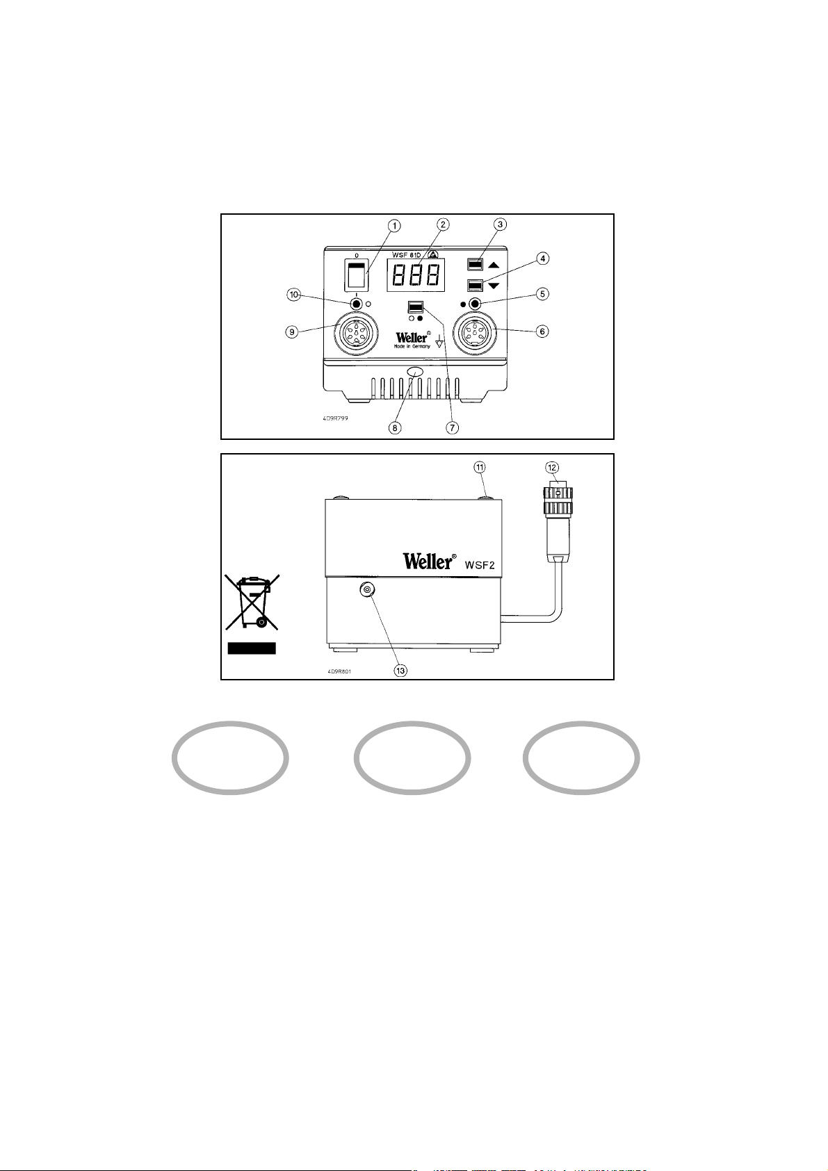
1. Netzschalter
2. Digitalanzeige
3. „UP“ Taste
4. „DOWN“ Taste
5. Anzeige Kanalwahl
/ Vorschubfunktion
6. Anschlussbuchse Vorschubeinheit
7. Kanalwahltaste
8. Potentialausgleichsbuchse
9. Anschlussbuchse Lötkolben
10. Anzeige Kanalwahl / Optische
Regelkontrolle Lötkolben
11. Verriegelung Deckel
Vorschubeinheit
12. Anschlussstecker Vorschubeinheit
13. Anschluss für Drahtführung
Lötkolben
1. Interrupteur secteur
2. Afficheur numérique
3. Touche „UP“
4. Touche „DOWN“
5. Témoin de sélection du canal /
fonction d’avance
6. Prise pour l’unité d’avance
7. Touche de sélection du canal
8. Prise d’équipotentialité
9. Prise pour le fer à souder
10. Témoin de sélection du canal /
contrôle visuel de réglage du fer à
souder
11. Verrouillage couvercle unité
d’avance
12. Fiche pour l’unité d’avance
13. Connexion pour guide fil du fer à
souder
1. Netschakelaar.
2. Digitale indicatie.
3. „UP“ toets.
4. „DOWN“ toets.
5. Indicatie kanaal-keuze / vooruitduwfunctie.
6. Aansluitbus vooruitduweenheid.
7. Kanaalkeuzetoets.
8. Equipotentiaalbus
9. Aansluitbus soldeerbout.
10. Indicatie kanaalkeuze / opti sche
regelcontrole soldeerbout.
11. Vergrendeling deksel vooruitdu
weenheid
12. Aansluitsteller vooruitduweenheid.
13. Aansluiting voor draadgeleiding sol
deerbout
FIN
P
1. Interruptor geral
2. Mostrador digital
3. Botão „UP“
4. Botão „DOWN“
5. Indicação selecção de canal /
função de avanço
6. Tomada para ligação da unidade
de avanço
7. Botão de selecção de canal
8. Tomada da ligação equipotencial
9. Tomada para ligação do ferro de
soldar
10. Indicação do canal seleccionado/
controlo de regulação óptico para o
ferro de soldar
11. Travamento da tampa da unidade
de avanço
12. Conector para a unidade de
avanço
13. Ligação para a guia de arame do
ferro de soldar
DK
1. Netafbryder
2. Digitalvisning
3. ”UP”-taste
4. ”DOWN”-tast
5. Visning kanalvalg / fremførings
funktion
6. Tilslutningsbøsning
fremføringsenhed
7. Kanalvalgstast
8. Potentialudligningsbøsning
9. Tilslutningsbøsning loddekolbe
10. Visning kanalvalg / optisk regula
tor-kontrol loddekolbe
11. Lås låg fremføringsenhed
12. Tilslutningsstik fremføringsenhed
13. Tilslutning til loddekolbens trådfø
ring
E
SGB
I
1. Main switch
2. Digital display
3. ”Up” key
4. ”Down” key
5. Display for channel selection /
feed function
6. Socket for feed unit
7. Channel selector key
8. Equipotential bonding socket
9. Socket for soldering iron
10. Display for channel selection /
optical soldering iron controller
11. Locking pin cover (feeder unit)
12. Plug for feed unit
13. Connecting the soldering iron wire
lead
1. Nätkontakt
2. Digital display
3. ”UP”-tangent
4. ”DOWN”-tangent
5. Indikering val av kanal
6. Anslutning frammatningsfunktion
7. Tangent för val av kanal
8. Potentialutjämningskontakt
9. Anslutning för lödkolv
10. Indikering av kanalval / visuell
regleringskontroll lödkolv
11. Låsanordning lock till frammat
ningsenhet
12. Anslutningskontakt för
frammatningsenhet
13. Anslutning för lödkolvens trådstyr
ning
GR
1. Interruttore di rete
2. Display
3. Tasto ”UP”
4. Tasto ”DOWN”
5. Indicatore selezione canale /
Funzione di avanzamento
6. Presa di collegamento unità di avanza
mento
7. Tasto di selezione canale
8. Presa di equalizzazione dei potenziali
9. Presa di collegamento stilo saldante.
10. Indicatore selezione canale / Controllo
ottico della regolazione per stilo sadate.
11. Chiusura coperchio unità di avanzmeto
12. Connettore per unità di avanzamento
13. Collegamento per conduzione filo
allo stilo saldante.
1. ∏ПВОЩЪИОfi˜ ‰И·ОfiЩЛ˜
2. æËÊȷ΋ ¤Ó‰ÂÈÍË
3. ¶Ï‹ÎÙÚÔ „UP“
4. ¶Ï‹ÎÙÚÔ „DOWN“
5. ŒÓ‰ÂÈÍË ÂÈÏÔÁ‹˜ ηӷÏÈÔ‡ / §ÂÈÙÔ˘ÚÁ›· ÚÔÒıËÛ˘
6. ™˘Ó‰ÂÙ‹ÚÈ· ˘Ô‰Ô¯‹ ÁÈ· ÙË ÌÔÓ¿‰· ÚÔÒıËÛ˘
7. ¶Ï‹ÎÙÚÔ ÂÈÏÔÁ‹˜ ηӷÏÈÔ‡
8. ÀÔ‰Ô¯‹ Â͛ۈÛ˘ ‰˘Ó·ÌÈÎÔ‡
9. ™˘У‰ВЩ‹ЪИ· ˘Ф‰Ф¯‹ БИ· ЩФ ¤М‚ФПФ Ы˘БОfiППЛЫЛ˜
10. ŒУ‰ВИНЛ ВИПФБ‹˜ О·У·ПИФ‡ / √ЩИОfi˜ Ъ˘ıМИЫЩИОfi˜ ¤ПВБ¯Ф˜
ЩФ˘ ВМ‚fiПФ˘ Ы˘БОfiППЛЫЛ˜
11. ª·У‰¿ПˆЫЛ О··ОИФ‡ МФУ¿‰·˜ ЩЪФКФ‰ФЫ›·˜
12. ™˘Ó‰ÂÙ‹ÚÈÔ ‚‡ÛÌ· Ù˘ ÌÔÓ¿‰·˜ ÚÔÒıËÛ˘
13. ™‡У‰ВЫЛ Ф‰ЛБФ‡ Ы‡ЪМ·ЩФ˜ ОФППЛЩЛЪИФ‡
1. Interruptor de red
2. Indicación digital
3. Tecla «UP» (arriba)
4. Tecla «DOWN» (abajo)
5. Indicación selección de canal / funci
ón de avance
6. Manguito de conexión unidad de
avance
7. Selector de canal
8. Manguito de compensación del
potencial
9. Manguito de conexión soldador
10. Indicación selección de canal /
control óptico de regulación soldador
11. Tapa de cierre de la unidad de
avance
12. Conector de conexión unidad de
avance
13. Conexión para guía de hilo del solda
dor
1. Verkkokytkin
2. Digitaalinäyttö
3. Näppäin UP
4. Näppäin DOWN
5. Näyttö kanavanvalinta / syöttötoiminto
6. Syöttöyksikön liitäntärasia
7. Kanavanvalintanäppäin
8. Potentiaalintasausrasia
9. Juottokolvin liitäntärasia
10. Näyttö kanavanvalinta/ juottokolvin optinen säätövalvonta
11. Syöttöyksikön kannen lukitus
12. Syöttöyksikön liitäntäpistoke
13. Juottokolvin langanohjaimen liitäntä
LV
LT
SLO
SK
H
PL
CZ
EST
TR
1 Ωebeke μalteri
2. Dijital gösterge
3. "UP" (yukar∂) tuμu
4. "DOWN" (aμaπ∂) tuμu
5. Kanal seçimi / besleme fonksiyonu göstergesi
6. Besleme ünitesi baπlant∂ yuvas∂
7. Kanal seçme tuμu
8. Potansiyal dengeleme fiμ yuvas∂
9. Lehim havyas∂ baπlant∂ yuvas∂
10. Kanal seçme / Lehim havyas∂
optik ayar kontrolü
11. Besleme ünitesi kapaπ∂n∂n kilidi
12. Besleme ünitesi baπlant∂ soketi
13. Lehim havyas∂ kablo baπlant∂s∂
1. W∏àcznik sieciowy
2. Wskaênik cyfrowy
3. Przycisk UP
4. Przycisk DOWN
5. Wskaênik wyboru kana∏u / funkcja podajnikowa
6. Gniazdo przy∏àczeniowe jednostki
podajnikowej
7. Przycisk wyboru kana∏u
8. Gniazdo wyrównania potencja∏u
9. Gniazdo przy∏àczeniowe lutownicy
10. Wskaênik wyboru kana∏u / Optyczna kontrola regulacji lutownicy
11. Pokrywa blokujàca jednostki podajnikowej
12. Wtyczka przy∏àczeniowa jednostki
podajnikowej
13. Przy∏àcze dla prowadzenia lutowia lutownicy
1. hálózati kapcsoló
2. digitális kijelzŒ
3. UP gomb
4. DOWN gomb
5. csatornaválasztás / elŒtolás kijelzŒ
6. elŒtolóegység csatlakozóhüvelye
7. csatornaválasztó gomb
8. PotenciálkiegyenlítŒ hüvely
9. Forrasztópáka csatlakozóhüvelye
10. csatornaválasztás / forrasztópáka
optikai szabályozóellenŒrzŒjének
kijelzŒje
11. elŒtolóegység fedelének reteszelése
12. elŒtolóegység csatlakozódugója
13. forrasztópáka drótvezetŒjének
csatlakozója
1. SieÈov˘ vypínaã
2. Digitálny ukazovateº
3. Tlaãidlo UP
4. Tlaãidlo DOWN
5. Ukazovateº v˘ber kanálov / posunovacia funkcia
6. Pripájacia zásuvka posunovacej jed
notky
7. Tlaãidlo voºby kanálu
8. Prípojka pre vyrovnanie napätia
9. Zásuvka pre pripojenie spájkovaãky
10. Ukazovateº v˘ber kanálov / optická
kontrola regulácie spájkovaãky
11. Blokovanie veka posunovacej jednotky
12. Zástrãka prípojky posunovacej jed
notky
13. Prípojka vedenia drôtu spájkovaãky
1. OmreÏno stikalo
2. Digitalni prikaz
3. Tipka UP
4. Tipka DOWN
5. Prikaz izbira kanala / funkcija podajanja
6. Prikljuãna doza enote za podajanje
7. Tipka za izbiro kanala
8. Pu‰a za izenaãevanje potenciala
9. Prikljuãna doza za spajkalnik
10. Prikaz izbira kanala / vizualna kontrola regulacije spajkalnika
11. Zapora pokrova enote za podajanje
12. Prikljuãni vtiã enote za podajanje
13. Prikljuãek za vodenje Ïice spajkalnika
1. Võrgulüliti
2. Digitaalnäidik
3. "UP" klahv
4. "DOWN" klahv
5. Kanalivaliku näidik / ettenihkefunktsioon
6. Ettenihkeseadeldise ühendspuks
7. Kanalivaliku klahv
8. Potentsiaalide ühtlustuspuks
9. Jootekolvi ühenduspuks
10. Kanalivaliku näidik / jootekolvi
optiline reguleerimiskontroll
11. Ettenihkeseadeldise katte fiksaator
12. Ettenihkeseadeldise ühenduspi
stik
13. Jootekolvi traadijuhiku ühenskoht
1. Tinklo jungiklis
2. Skaitmeninis indikatorius
3. Mygtukas „UP"
4. Mygtukas „DOWN"
5. Kanal˜ pasirinkimo indikatorius /
pastmos funkcija
6. Pastmos bloko prijungimo lizdas
7. Kanal˜ pasirinkimo mygtukas
8. Potencial˜ i‰lyginimo lizdas
9. Lituoklio prijungimo lizdas
10. Kanal˜ pasirinkimo indikatorius /
lituoklio optinò valdymo kontrolò
11. Pastmos bloko uÏdarymo dangtelis
12. Pastmos bloko prijungimo ki‰tukas
13. Lituoklio vielos kreipiamosios jungtis
1. Elektr¥bas baro‰anas slïdzis
2. DigitÇlie rÇd¥jumi
3. "UP" (Aug‰up) tausti¿‰
4. "DOWN" (Lejup) tausti¿‰
5. RÇd¥jums KanÇla izvïle/ Padeves
funkcija
6. Pieslïguma bukse Padeves vien¥ba
7. KanÇla izvïles tausti¿‰
8. PotenciÇlu izl¥dzinljanas bukse
9. LodÇmura pieslïgbukse
10. RÇd¥jums KanÇla izvïle / OptiskÇ
vad¥bas kontrole LodÇmurs
11. Aizslïgs PÇrsegs Padeves vien¥ba
12. Pieslïguma spraudnis Padeves
vien¥ba
13. Pieslïgums lodÇmura stieples vadotnei
1. SíÈov˘ vypínaã
2. Displej
3. Tlaãítko UP
4. Tlaãítko DOWN
5. Indikace zvolení kanálu / funkce
podávání
6. Zásuvka pro pfiipojení podávací
jednotky
7. Tlaãítko volby kanálu
8. Zdífika pro vyrovnání potenciálÛ
9. Zásuvka pro pfiipojení pájeãky
10. Indikace zvolení kanálu / optická
kontrola regulace pájeãky
11. Zaji‰Èovací prvky víka podávací jednotky
12. Pfiipojovací zástrãka podávací jed
notky
13. Pfiípojka pro vedení drátu pájeãky

NLFD
14. Netzanschluss
15. Netzsicherung
16. Anschlussbuchse für externe
Auslösung und potentialfreiem
Kontakt.
17. Klemmschraube für Lötkolben-
drahtführung
18. Drahteinführung
19. Rändelmutter für
Zinnrollenbefestigung
14. Connecteur secteur
15. Fusible secteur
16. Prise pour le déclenchement
externe et le contact libre de
potentiel
17. Vis de serrage pour le guide fil du
fer à souder
18. Entrée du câble
19. Ecrou moleté pour la fixation de la
bobine de soudure
14. Netaansluiting
15. Netzekering.
16. Aansluitbus voor externe active
ring en potentiaalvrij contact.
17. Klemschroef voor soldeerdraadge
leiding
18. Draadinvoer.
19. Kartelmoer voor bevestiging rol
soldeertin.
FIN
14. Verkkoliitäntä
15. Päävirtapiirikatkaisin
16. Liitäntärasia ulkoiselle laukaisulle
ja potentiaalivapaalle koskettimelle
17. langenohjaimen lukitusruuvi
18. Langanohjaus
19. Pyälletty mutteri tinarullan
kiinnitykseen
P
14. Ligação à rede
15. Fusível de rede
16. Tomada para ligação do
disparo externo e contacto isen
to de potencial
17. Parafuso de fixação para a guia
de arame do ferro de soldar
18 Entrada de arame
19. Porca serrilhada para a fixação
do rolo de estanho
DK
14. Nettilslutning
15. Netsikring
16. Tilslutningsbøsning til ekstern
udløsning og potentialfri kontalt
17. Klemskrue til loddekolbens
trådføring
18. Trådåbning
19. Fingermøtrik til fastgørelse af
tinrullen
E
SGB
I
14. Main power connection
15. Main fuse
16. Connecting socket for external
triggering and floating contact
17. Clamping screw for the soldering
iron wire lead
18. Wire infeed
19. Knurled nut for attaching older
roll
14. Nätanslutning
15. Nätsäkring
16. Anslutning för extern utlösning och
potentialfri kontakt
17. Låsskruv för lödkolvens trådstyrning
18. Trådinmatning
19. Räfflad mutter för fastsättning av
tennrulle.
TR
GR
14. Collegamento a rete
15. Fusibile di rete
16. Presa di collegamento per
dispositivo di azionamento esterno
e contatto libero da potenziale
17. Vite di bloccaggio per il connettore
del tubo per il filo di lega allo stilo
saldante.
18. Guida per inserimento filo di lega.
19. Dado zigrinato per fissaggio roccet
ti di stagno.
14. ™‡У‰ВЫЛ ЫЩФ ЛПВОЩЪИОfi
‰›ОЩ˘Ф
15. ∞ЫК¿ПВИ· ЛПВОЩЪИОФ‡ ‰ИОЩ‡Ф˘
16. ™˘У‰ВЩ‹ЪИ· ˘Ф‰Ф¯‹ БИ·
ВНˆЩВЪИО‹ ВУВЪБФФ›ЛЫЛ О·И
БИ· ВПВ‡ıВЪЛ ‰˘У·МИОФ‡
·ʋ
17. 웉· Ы˘БОЪ¿ЩЛЫЛ˜ Ф‰ЛБФ‡
Ы‡ЪМ·ЩФ˜ ОФППЛЩЛЪИФ‡
18. ∂ÈÛ·ÁˆÁ‹ Û‡ÚÌ·ÙÔ˜
19. ∞˘Ï·ÎˆÙfi ÂÚÈÎfi¯ÏÈÔ ÁÈ· ÙË
ÛÙÂÚ¤ˆÛË ÙÔ˘ ηÚÔ˘ÏÈÔ‡
ηÛÛÈÙ¤ÚÔ˘
14. Conexión de red
15. Fusible
16. Manguito de conexión para activa
ción externa y contacto libre de
potencial
17. Tornillo de fijación para guía de hilo
del soldador
18 Pasa-hilos
19. Tuerca moleteada para sujetar el
rollo de estaño
14. Ωebeke baπlant∂s∂
15. Ωebeke sigortas∂
16. Harici devreye alma ve potansiyel
bak∂m∂ndan serbest kontak için
baπlant∂ fiμ yuvas∂.
17. Lehim havyas∂ kablo baπlant∂s∂ için
klemens vidas∂
18. Kablo baπlant∂s∂
19. Lehim makaras∂n∂ sabitlemek için
t∂rt∂ll∂ somun
LVLT
SLO
SK
HPL
CZ
EST
14. SíÈová pfiípojka
15 SíÈová pojistka
16. Pfiipojovací zásuvka pro externí spínání a bezpotenciálov˘
kontakt.
17. Stahovací ‰roub pro vedení
drátu pájeãky
18. Zavedení drátu
19. R˘hovaná matice pro upevnûní
cívky cínu
14. Przy∏àcze sieciowe
15. Bezpiecznik sieciowy
16. Gniazdo przy∏àczeniowe dla zewn´trznego wyzwolenia i bezpotencja∏owego z∏àcza.
17. Âruba zaciskowa dla prowadnika
lutowia
18. Prowadnik lutowia
19. Nakr´tka rade∏kowa dla mocowania szpuli z cynà
14. hálózati csatlakozás
15. hálózati biztosíték
16. külsŒ kioldó és pontenciálmentes
érintkezŒ csatlakozóhüvelye
17. forrasztópáka drótvezetŒjének rögzítŒcsavarja
18. drótbevezetés
19. recézett anyag az óntekercs rögzítésére
14. SieÈová prípojka
15. SieÈov˘ istiã
16. Pripojovacia zásuvka pre externé spínanie a bezpotenciálov˘
kontakt.
17. ZaisÈovacia skrutka pre vedenie
drôtu spájkovaãky
18. Zavedenie drôtu
19. Vrúbkovaná matica na upevnenie zvitku s cínom
14. OmreÏni prikljuãek
15. OmreÏna varovalka
16. Prikljuãna doza za zunanje aktiviranje in kontakt brez potenciala.
17. Privojni vijak za vodilo Ïice spajkalnika
18. Vodilna odprtina
19. Narebriãena matica za pritrditev
koluta z Ïico
14. Võrgupistik
15. Võrgukaitse
16. Välise sisselülitamise ja potentsiaalivaba kontakti ühenduspuks.
17. Jootekolvi traadijuhiku klemmkruvi
18. Traadi sisseviik
19. Tinarullikinnituse mutter
14. Lizdas elektros tinklui prijungti
15. Tinklo saugiklis
16. Prijungimo lizdas i‰oriniam ∞jungimui ir nepotencialiniam kontaktui.
17. Lituoklio vielos kreipiamosios
fiksavimo varÏtas
18. Vielos ∞vadas
19. VerÏlò alavo ritinòliui tvirtinti
14. Pieslïgums t¥klam
15. Elektr¥bas t¥kla dro‰¥bas elements
16. Pieslïguma bukse Çrïjai iedarbinljanai un bezpotenciÇla kontaktam.
17. FiksÇcijas skrve lodÇmura stieples vadotnei
18. Stieples ievade
19. Regulïjami uzgrieÏ¿i alvas ritu∫a
nostiprinljanai

1
Deutsch
Wir danken Ihnen für das mit dem Kauf der Weller Lötstation
WSF 81 D5 / D8 erwiesene Vertrauen. Bei der Fertigung wurden strengste Qualitäts-Anforderungen zugrunde gelegt, die
eine einwandfreie Funktion des Gerätes sicherstellen.
1. Achtung!
Vor Inbetriebnahme des Gerätes lesen Sie bitte diese
Betriebsanleitung und die beiliegenden Sicherheitshinweise
aufmerksam durch. Bei Nichteinhaltung der Sicherheitsvorschriften droht Gefahr für Leib und Leben.
Für andere, von der Betriebsanleitung abweichende Verwendung, sowie bei eigenmächtiger Veränderung, wird von
Seiten des Herstellers keine Haftung übernommen.
Die Weller Lötstation WSF 81 D5/D8 entspricht der EG
Konformitätserklärung gemäß den grundlegenden
Sicherheitsanforderungen der Richtlinien 89/336/EWG und
73/23EWG.
2. Beschreibung
Die Lötstation WSF 81 D5/D8 gehört einer Gerätefamilie an,
die für die industrielle Fertigungstechnik, sowie für den
Reparatur- und Laborbereich entwickelt wurde.
Die Lötstation beinhaltet ein automatisches Lötzinnvorschubsystem. Die verwendbaren Lötdrahtdurchmesser sind
in zwei Bereiche aufgeteilt und werden durch den angeschlossenen Lötkolben bestimmt (0,5 mm - 0,8 mm mit
Lötkolben WSF P5 und 0,8 mm - 1,5 mm mit Lötkolben WSF
P8) Vorschubseinheit und Steuergerät können platzsparend
übereinander gestapelt werden.
Das Steuergerät beinhaltet die digitale Elektronik für
Lötkolbenregelung (Kanal 1) und Vorschubsteuerung (Kanal
2). Durch den Einsatz eines Mikroprozessors wird ein optimales Temperaturregelverhalten an unterschiedlichen
Lötwerkzeugen und eine präzise Vorschubsteuerung des
Lötdrahtes erzielt.
Die Temperatur der Lötkolbenspitze (Kanal 1) wird digital
angezeigt und ist im Bereich von 50°C bis 450°C stufenlos
einstellbar. Das Erreichen der vorgewählten Temperatur wird
durch Blinken einer roten LED in der Anzeige signalisiert, die
zur optischen Regelkontrolle dient. Dauerndes Leuchten
bedeutet, dass das System aufheizt.
Mit einer integrierten Temperaturüberwachungsschaltung
können verschiedene Temperaturzustände über einen potentialfreien Kontakt ausgewertet werden.
In der Vorschubseinheit ist der mechanische Antrieb für den
Zinnvorschub und der Lötkolbenanschluss für die
Drahtführung enthalten. Ein Zinnrollenhalter bis max. 1kg
Lotdraht ist ebenfalls Bestandteil der Vorschubseinheit.
Die Abstimmung des mech. Antriebs auf den Drahtdurchmesser erfolgt automatisch.
Der WSF Lötkolben zeichnet sich durch seine ergonomische
Konstruktion mit einem beweglichen Heizelement aus. Durch
das besonders leistungsfähige 80 W Heizelement wird die
Löttemperatur präzise und schnell erreicht. Der Winkel des
beweglichen Heizelements lässt sich nach Lösen der
Arretierschraube (20) um ca. 40° verstellen.
Beim Arbeiten mit einem Zinnvorschubsystem lassen sind
prinzipiell zwei Arten unterscheiden:
Modus SFA automatic:
Im Betriebsmodus SFA wird durch kurzes Betätigen des
Fingerschalters (optional Fussschalter oder externer Kontakt)
die voreingestellte Lotmenge vorgeschoben. Die benötigte
Lotmenge kann stufenlos von ca. 1 – 10mm eingestellt werden. Die Vorschubszeit (Kanal 2) wird digital angezeigt.
Modus SFC continuous:
Beim Betriebsmodus SFC ist der Zinnvorschub aktiviert
solange der Fingerschalter (optional Fussschalter oder externer Kontakt) betätigt wird. Die Drehzahl (Geschwindigkeit)
des Vorschubes lässt sich stufenlos einstellen und wird auf
Kanal 2 digital angezeigt.
Verschiedene Potentialausgleichsmöglichkeiten zur
Lötspitze, Nullspannungsschaltung sowie die antistatische
Ausführung der Lötstation ergänzen den hohen
Qualitätsstandard.
Mit den als Option erhältlichen Eingabegeräten WCB 1 und
WCB 2 können ergänzende Zusatzfunktionen und
Einstellungen an der Lötstation vorgenommen werden.
Integriertes Temperaturmessgerät und PC-Schnittstelle
gehören zum erweiterten Funktionsumfang des
Eingabegerätes WCB 2.
3. Bedienung und Einstellung
Kanalwahl
Durch das Betätigen der Kanalwahltaste (7) kann die
Digitalanzeige auf Kanal 1 (Temperaturregelung) oder Kanal
2 (Vorschub) eingestellt werden. Der jeweils angezeigte
Kanal ist durch eine rot/orange Leuchtdiode über der
Anschlussbuchse (6) oder (9) gekennzeichnet.
Wenn keine Tasten betätigt werden schaltet das Gerät nach
ca. 10 sec automatisch auf Kanal 1 um und zeigt den
Temperaturistwert an.

2
Deutsch
Temperatureinstellung (Kanal 1)
Ohne Tastendruck zeigt die Digitalanzeige (2) den
Temperaturistwert an. Durch Betätigen der “UP” oder
“DOWN” -Taste (3)(4) schaltet die Digitalanzeige (2) auf den
derzeit eingestellten Sollwert um. Der eingestellte Sollwert
(blinkende Anzeige) kann nun durch Antippen oder permanentes Drücken der “UP” oder “DOWN” -Taste (3)(4) in entsprechender Richtung verändert werden. Wird die Taste permanent gedrückt, verändert sich der Sollwert im
Schnelldurchlauf. Ca. 2 sec. nach dem Loslassen schaltet
die Digitalanzeige (2) automatisch wieder auf den Istwert
um.
Standardsetback
Bei Nichtgebrauch des Lötwerkzeuges wird die Temperatur
nach 20 min. automatisch auf den Stand by Wert von 150°C
(300°F) abgesenkt. Nach dreifacher Setbackzeit (60 min.)
wird die „AUTO OFF“ Funktion aktiviert. Der Lötkolben wird
abgeschalten.
Einschalten der Standardsetback-Funktion: Während des
Einschaltens des Gerätes die „UP“ Taste gedrückt halten bis
in der Anzeige „ON“ erscheint. Gleiches Verfahren zum
Ausschalten. In der Anzeige erscheint „OFF“ (Auslieferungszustand).
Bei der Verwendung von sehr feinen Lötspitzen kann die
Funktionssicherheit beeinträchtigt sein.
Vorschubeinstellung (Kanal 2)
Nach dem Umschalten auf Kanal 2 zeigt die Digitalanzeige
(2) die Drehzahl beim SFC Modus oder die Vorschubszeit
beim SFA Modus an. Der eingestellte Wert kann nun durch
Antippen oder permanentes Drücken der “UP” oder “DOWN”
-Taste (3)(4) in entsprechender Richtung verändert werden.
Wird die Taste permanent gedrückt, verändert sich der
Sollwert im Schnelldurchlauf. Wenn keine Tasten betätigt
werden schaltet das Gerät nach ca. 10 sec automatisch auf
Kanal 1 um und zeigt den Temperaturistwert an.
Einstellbereiche:
SFA Modus Vorschubszeit (Lotmenge)
1 - 300 (10ms Schritte)
SFC Modus Drehzahl (Geschwindigkeit)
10% - 100%
Schnellvorschub:
Durch gleichzeitiges Drücken der Taste “UP” und “DOWN”
erfolgt der Lötdrahtvorschub mit max. Geschwindigkeit
(100%).
Empfohlen zum Nachschieben des Lotdrahtes nach dem
Zinnrollenwechsel.
SFA / SFC Modus Umschaltung:
Kanalwahltaste (7) gedrückt halten und mit der “UP” Taste
(3) den gewünschten Modus einstellen. In der Anzeige
erscheint der eingestellte Betriebsmodus.
Einstellung Temperaturfenster
Kanalwahltaste (7) und “DOWN” (4) gleichzeitig drücken. In
der Anzeige erscheint blinkend der Wert (in °C/°F) des
aktuell eingestellten Temperaturfensters (Werksseitig auf
“000” eingestellt).
Die werksseitige Einstellung “000” bedeutet:
Temperaturüberwachungsschaltung ist ausgeschalten und
der potentialfreie Kontakt (16) ist immer niederohmig.
°C Anzeige
Die Einstellung “ 001 – 099 ” entspricht:
Größe des Temperaturfensters + - 1°C bis + - 99°C
°F Anzeige
Die Einstellung “ 001 – 178 ” entspricht:
Größe des Temperaturfensters +- 1°F bis +-178°F
Potentialfreier Kontakt
Befindet sich die Isttemperatur des Lötwerkzeugs innerhalb
des eingestellten Temperaturfensters (Toleranzbreite) wird
der potentialfreier Kontakt (16) niederohmig geschalten.
Befindet sich die Temperatur außerhalb des eingestellten
Temperaturfensters wird dies in der Anzeige (2) mit “ HI”
Technische Daten
Abmessungen (B X T X H): 120 X 217 X 199
Netzspannung: 230 V / 50 Hz
Ausgangsspannung: 24 VAC (Kanal 1); 24 VDC (Kanal 2)
Leistung: 90 W
Sicherung: T800mA
Temperaturregelung: stufenlos 50°C – 450°C
Genauigkeit: + - 9°C
Potentialausgleich: Grundzustand hart geerdet

(High; Temperatur zu hoch) oder “LO” (Low, Temperatur zu
niedrig) im 2 sec. Takt angezeigt und der potentialfreie
Kontakt (16) ist hochohmig.
Der Transistorausgang eines Optokopplers stellt den potentialfreien Kontakt des Gerätes dar. Es ist daher auf die Polarität
der zu schaltenden Spannung zu achten.
PLUS (+) an Pin 2
MINUS (-) an Pin 3
Belastbar ist dieser Kontakt mit max. 24 V / 20mA
Externes Eingabegerät WCB 1 und WCB 2 (Option)
Bei der Verwendung eines externen Eingabegeräres stehen
folgende Funktionen zur Verfügung.
●
Offset:
Die tatsächliche Lötspitzentemperatur kann durch die
Eingabe eines Temperaturoffsets um +/- 40°C verändert
werden.
●
Setback:
Herabsetzung der eingestellten Solltemperatur auf 150°C
/300°F (Stand by). Die Setbackzeit, nachdem die Lötstation
in den Stand by Modus wechselt, ist von 0 – 99 Minuten einstellbar. Der Setbackzustand wird durch eine blinkende
Istwertanzeige signalisiert. Nach dreifacher Setbackzeit wird
die “AUTO OFF” Funktion aktiviert. Das Lötwerkzeug wird
abgeschaltet (blinkender Strich in der Anzeige). Durch
Drücken einer Taste oder Fingerschalterdruck wird der
Setbackzustand bzw. “AUTO OFF” Zustand beendet. Dabei
wird kurzzeitig der eingestellte Sollwert angezeigt.
●
Lock:
Verriegelung von Solltemperatur und Temperaturfenster.
Nach dem Verriegeln sind an der Lötstation keine
Einstelländerungen möglich.
●
°C / °F:
Umschalten der Temperaturanzeige von °C in °F und umgekehrt. Drücken der “DOWN” Taste während des Einschaltens
zeigt die aktuelle Temperaturversion an.
●
Window:
Einschränkung des Temperaturbereiches auf max. +/-99°C
ausgehend von einer durch die „LOCK“ Funktion verriegelten
Temperatur. Die verriegelte Temperatur stellt somit die Mitte
des einstellbaren Temperaturbereiches dar.
Bei Geräten mit potentialfreiem Kontakt (Optokopplerausgang) dient die „WINDOW“ Funktion zur Einstellung eines
Temperaturfensters. Liegt die Isttemperatur innerhalb des
Temperaturfensters wird der potentialfreie Kontakt (Optokopplerausgang) durchgeschaltet.
●
Cal:
Factory setting FSE (Rücksetzen aller Einstellwerte auf 0,
Temperatursollwert 350°C/660°F)
●
PC-Schnittstelle:
RS232 (nur WCB 2)
●
Temperatur-Messgerät:
Integriertes Temperaturmessgerät für Thermoelement Typ K
(nur WCB 2)
Wartung
Bei ungleichmäßigem Vorschub sollte das Antriebsrad mit
einer Messingbürste gereinigt werden. Dazu Steuergerät von
der Vorschubseinheit entfernen. Den Deckel der
Vorschubseinheit nach hinten klappen um die
Vorschubseinheit zugänglich zu machen. Anschließend
Antriebsrad abheben und reinigen.
4. Inbetriebnahme
Die Vorschubseinheit mit dem Steuergerät elektrisch miteinander verbinden. Stecker (12) in Buchse (6).
Die Lötkolbenanschlüsse mit dem Steuergerät und der
Vorschubseinheit verbinden. Elektrischer Anschlussstecker
des Lötkolbens in die 7 pol. Anschlussbuchse (9) des
Steuergerätes einstecken und arretieren. Die Drahtführung in
das Verbindungselement (13) der Vorschubseinheit bis zum
Anschlag einführen und mit der Klemmschraube (17) fixieren.
Den Lötkolben in die Sicherheitsablage ablegen.
Bei korrekter Netzspannung das Steuergerät mit dem Netz
(14) verbinden. Gerät einschalten (1).
Zinnrolle montieren
Rändelmutter (19) des Zinnrollenhalters demontieren. Die
Zinnrolle so auf die Welle stecken, dass der Lotdraht nach
unten abgerollt wird. Die Zinnrolle mit der Rändelmutter
sichern und den Drahtanfang in die Einführungsöffnung (18)
schieben.
Durch gleichzeitiges Betätigen der “UP” und “DOWN” Taste
wird der Lötdraht vom Antrieb erfasst und mit der max.
Geschwindigkeit transportiert. Lötdraht bis zum Erscheinen
an der Lötkolbenzuführdüse (22) tranportieren.
Der Deckel der Vorschubseinheit lässt sich nach hinten klappen, um die Antriebseinheit zugänglich zu machen, falls der
Lotdraht vom Antrieb nicht erfasst wird. Die beiden
Verriegelungselemente des Deckels lassen sich durch eine
ca. 90° Drehung nach links öffnen.
3
Deutsch

4
Anschließend Geräteeinstellungen wie in Abschnitt
“Bedienung und Einstellung” vornehmen.
5. Potentialausgleich
Durch unterschiedliche Beschaltung der 3,5 mm
Schaltklinkenbuchse (8) sind 4 Variationen realisierbar.
Hart geerdet:
Ohne Stecker (Auslieferungszustand)
Potentialausgleich (Impedanz 0 Ohm):
Mit Stecker, Ausgleichsleitung am Mittelkontakt
Potentialfrei:
Mit Stecker
Weich geerdet:
Mit Stecker und eingelötetem Widerstand. Erdung über den
gewählten Widerstandswert.
6. Löttechnische Hinweise
Beim ersten Aufheizen die selektiv verzinnbare Lötspitze mit
Lot benetzen. Diese entfernt lagerbedingte Oxydschichten
und Unreinheiten der Lötspitze. Bei Lötpausen und vor dem
Ablegen des Lötkolbens immer darauf achten, dass die
Lötspitze gut verzinnt ist. Bei sehr mild aktivierten
Flussmitteln (no clean) wird zur Aufrechterhaltung der
Benetzung die Verwendung von Tip Aktivator empfohlen.
Der Übergang zwischen Heizkörper / Sensor und der
Lötspitze darf nicht durch Schmutz, Fremdkörper oder
Beschädigung beeinträchtigt werden, da dies Auswirkungen
auf die Genauigkeit der Temperaturregelung hat.
Achtung: Immer auf ordnungsgemäßen Sitz der
Lötspitze achten.
Die Wärmeübertragunsflächen von Heizkörper und Lötspitze
sauber halten.
Die heiße Lötspitze nicht auf dem Reinigungsschwamm oder
Kunststoffoberflächen ablegen.
Die Lötgeräte wurden für eine mittlere Lötspitze bzw. Düse
justiert. Abweichungen durch Spitzenwechsel oder der
Verwendung von anderen Spitzenformen können entstehen.
7. Zubehör
005 13 120 99 Fussschalter
005 13 031 99 Tip Aktivator
Lötspitzen:
005 44 403 99 LT A 1,6 mm Meißel
005 44 405 99 LT B 2,4 mm Meißel
005 44 407 99 LT C 3,2 mm Meißel
005 44 443 99 LT ALX 1,6 mm gebogen
005 44 442 99 LT BX 2,4 mm gebogen
005 44 412 99 LT H 0,8 mm Meißel
005 44 420 99 LT HX 0,8 mm gebogen
005 44 408 99 LT F 1,2 mm Rundform abgeschrägt
005 44 444 99 LT BB 2,4mm Rundform abgeschrägt
005 44 445 99 LT CC 3,2 mm Rundform abgeschrägt
8. Lieferumfang
Steuergerät
Vorschubeinheit
WSF P Lötkolben
Kleinwerkzeug
Lötkolbenablage
Netzkabel
Betriebsanleitung
Sicherheitshinweise
Technische Änderungen vorbehalten!
Deutsch

Nous vous remercions de la confiance que vous nous avez
accordée en achetant la station de soudage WSF 81
D5/D8. Lors de la fabrication, des exigences de qualité très
sévères assurant un fonctionnement parfait de l’appareil, ont
été appliquées.
1. Attention!
Avant la mise en service de l’appareil, veuillez lire attentivement ce mode d’emploi et les consignes de sécurité ci-jointes. Dans le cas du non-respect des consignes de sécurité, il
y a danger pour le corps et danger de mort.
Le fabricant décline toute responsabilité pour les utilisations
autres que celles décrites dans le mode d’emploi de même
que pour les modifications effectuées par l’utilisateur.
La station de soudage WSF 81 D5/D8 correspond à la déclaration de conformité européenne en application des exigences de sécurité fondamentales de la directive 89/336/CEE et
73/23/CEE.
2. Description
La station de soudage WSF 81 D5/D8 appartient à une série
d’appareils développés pour la fabrication industrielle de
même que pour les activités de réparation et de laboratoire.
La station de soudage comprend un système d’avance automatique du fil à souder. Les diamètres utilisables du fil à
souder sont subdivisés en deux catégories et sont fonction
du fer à souder raccordé (0,5 mm à 0,8 mm avec le fer à
souder WSF P5 et 0,8 mm à 1,5 mm avec le fer à souder
WSF P8). L’unité d’avance et l’appareil de commande peuvent être superposés pour gagner de la place.
L’appareil de commande renferme l’électronique numérique
de régulation de la panne (canal 1) et la commande de l’avance (canal 2). Le recours à un microprocesseur permet
d’obtenir des caractéristiques optimales de régulation de la
température avec différents outils de soudage et une commande précise de l’avance du fil à souder.
La température de la panne (canal 1) est indiquée par un afficheur numérique et est réglable en continu entre 50°C et
450°C. Lorsque la température présélectionnée est atteinte,
une LED rouge de contrôle visuel située dans l’afficheur se
met à clignoter. Cette LED est allumée de manière continue
pendant que le système chauffe.
Le circuit de surveillance de la température intégré permet
d’exploiter différentes températures par l’intermédiaire d’un
contact libre de potentiel.
L’unité d’avance renferme l’entraînement mécanique pour
l’avance du fil à souder et la connexion du fer à souder pour
le guide fil. L’unité d’avance comprend également un support de bobine de fil à souder de 1 kg maxi.
L’entraînement mécanique est adapté automatiquement au
diamètre du fil à souder.
Le fer à souder WSF se distingue par sa conception ergonomique et son élément chauffant mobile. Grâce à ce puissant
élément chauffant de 80 W, la température de soudage est
atteinte de manière précise et rapide. L’angle de l’élément
chauffant mobile peut être réglé d’environ 40° après avoir
desserré la vis de blocage (20).
Il existe deux modes de fonctionnement différents du système d’avance du fil à souder:
Mode SFA Sequentiel:
Dans le mode de fonctionnement SFA, un bref actionnement
du commutateur tactile (interrupteur à pédale ou contact
externe en option) commande l’avance de la quantité préréglée de soudure. La quantité de soudure peut être préréglée
en continu entre env. 1 et 10 mm. Le temps d’avance (canal
2) est indiqué par l’afficheur numérique.
Mode SFC Continu:
Dans le mode de fonctionnement SFC, l’avance du fil à souder est activée tant que le commutateur tactile (interrupteur
à pédale ou contact externe en option) est actionné. La vitesse de rotation (vitesse) de l’avance est réglable en continu et
est indiquée sur le canal 2 par l’afficheur numérique.
Différentes possibilités d’équilibrage du potentiel avec la
panne, une connexion à minimum de tension ainsi qu’une
exécution antistatique de la station de soudage complètent
cet équipement de qualité.
Les appareils d’entrée WCB1 et WCB2 disponibles en option
permettent d’exécuter des fonctions supplémentaires et
d’effectuer des réglages sur la station de soudage. Les fonctionnalités élargies de l’appareil d’entrée WCB2 comprennent un contrôleur de température intégré et une interface
pour PC.
3. Utilisation et réglages
Sélection du canal
L’affichage numérique peut être réglé sur le canal 1 (régulation de température) ou le canal 2 (avance) en actionnant la
touche de sélection du canal (7). Le canal affiché est signalé par une diode électroluminescente rouge/orange au-dessus de la prise de raccordement (6) ou (9).
Si aucune touche n’est actionnée, l’appareil revient automatiquement au canal 1 au bout d’environ 10 secondes et indique la température réelle.
5
Français

6
Réglage de la température (canal 1)
Si aucune touche n’est actionnée, l’afficheur numérique (2)
indique la température réelle. En actionnant la touche ”Up”
ou ”Down” (3)(4), l’afficheur numérique (2) indique la valeur
de consigne momentanément réglée. La valeur de consigne
réglée (affichage clignotant) peut être modifiée dans la
direction souhaitée en donnant des impulsions ou en exerçant une pression continue sur la touche ”Up” ou ”Down”
(3)(4). Lorsque la touche est actionnée en continu, la valeur
de consigne change rapidement. 2 secondes environ après
avoir relâché la touche, l’afficheur numérique (2) revient
automatiquement à la valeur réelle.
Réduction de température standard
Lorsque l’appareil de soudage n’est pas utilisé, la température est ramenée automatiquement à la valeur standard de
150°C (300°F) au bout de 20 minutes. Au bout de trois fois
cette durée (60 minutes), la fonction “AUTO OFF” est activée. Le fer à souder s’éteint.
Activation de la fonction de réduction de température
Setback standard: maintenir la touche “UP” enfoncée durant
la mise en marche de l’appareil jusqu’à ce que l’afficheur
indique “ON”. Procéder de la même manière à l’extinction.
L’afficheur indique “OFF” (état d’origine).
La fonction de sécurité peut être altérée lors de l’utilisation
de très fines pannes.
Réglage de l’avance (canal 2)
Lorsque le canal 2 a été sélectionné, l’afficheur numérique
(2) indique la vitesse de rotation dans le mode SFC ou le
temps d’avance dans le mode SFA. La valeur réglée peut
alors être modifiée dans la direction souhaitée en donnant
des impulsions ou en exerçant une pression continue sur la
touche ”Up” ou ”Down” (3)(4). Lorsque la touche est actionnée en continu, la valeur de consigne change rapidement. Si
aucune touche n’est actionnée, l’appareil revient automatiquement au canal 1 au bout d’environ 10 secondes et indique la température réelle.
Plages de réglage:
Mode SFA temps d’avance (quantité de soudure)
1 - 300 (pas de 10ms)
Mode SFC vitesse de rotation (vitesse)
10% - 100%
Avance rapide:
En actionnant simultanément les touches ”UP” et ”DOWN”,
l’avance du fil à souder se fait à la vitesse maximale (100%).
Cette vitesse est recommandée pour faire avancer le fil à
souder après un changement de bobine.
Mode SFA / SFC
Commutation:
Maintenir la touche de sélection du canal (7) enfoncée et
sélectionner le mode souhaité avec la touche „UP“ (3).
L’afficheur indique le mode de fonctionnement sélectionné.
Réglage de la fenêtre de températures
Actionner simultanément la touche de sélection du canal (7)
et ” Down ” (4). L’afficheur indique en clignotant la valeur
(en °C/°F) de la fenêtre de températures momentanément
réglée (réglage d’origine ”000”).
Le réglage d’origine ”000” signifie:
Le circuit de surveillance de température est désactivé et le
contact libre de potentiel (16) est toujours à basse impédance.
Affichage °C
Le réglage ” 001 – 099 ” correspond à:
Taille de la fenêtre de températures + - 1°C à + - 99°C
Affichage °F
Le réglage ” 001 – 178 ” correspond à:
Taille de la fenêtre de températures +- 1°F à +-178°F
Contact libre de potentiel
Si la température réelle de l’outil de soudage se situe dans
la fenêtre de températures (plage de tolérance) réglée, le
contact libre de potentiel (16) est commuté sur basse impédance. Si la température se situe en dehors de la fenêtre de
Français
Caractéristiques techniques
Dimensions (L X P X H): 120 X 217 X 199
Tension secteur: 230 V / 50 Hz
Tension de sortie: 24 V AC (canal1); 24 V DC (canal2)
Puissance: 90 W
Fusible: T800mA
Régulation de température: en continu 50 °C – 450 °C
Précision: + - 9 °C
Equilibrage du potentiel: mise à la terre dure d’origine

températures réglée, l’afficheur (2) le signale par ” HI” (High;
température trop élevée) ou ”LO” (Low, température trop
basse) au rythme de 2 secondes et le contact libre de potentiel (16) est à haute impédance.
La sortie transistorisée d’un coupleur optoélectronique
représente le contact libre de potentiel de l’appareil. La polarité de la tension à commuter doit par conséquent être
observée.
PLUS (+) à la broche 2
MOINS (-) à la broche 3
La charge admissible maximale de ce contact est de 24V /
20mA
Appareil d’entrée externe WCB 1 et WCB 2 (option)
Les fonctions suivantes sont à disposition lors de l’utilisation
d’un appareil d’entrée externe:
●
Offset:
La température réelle de la panne peut être modifiée de + 40°C par l’entrée d’un offset de température.
●
Setback:
Réduction de la température de consigne réglée à 150°C
/300°F (Stand by). Le temps de Setback au bout duquel la
station de soudage se met en Stand by est réglable entre 0
et 99 minutes. Le Setback est signalé par le clignotement
de la valeur réelle affichée.
La fonction AUTO OFF est activée au bout de trois fois la
durée de Setback. L’outil de soudage est désactivé (trait clignotant sur l’afficheur). Le Setback ou AUTO OFF est terminé
en appuyant sur une touche ou en actionnant le commutateur tactile. La valeur de consigne réglée est alors brièvement affichée.
●
Lock:
Verrouillage de la température de consigne et de la fenêtre
de températures. Après le verrouillage, aucun réglage de la
station de soudage ne peut être modifié.
●
°C / °F:
Commutation de l’affichage de température de °C sur °F et
inversement. En appuyant sur la touche ”Down” pendant la
mise en marche, la version de température en cours est affichée.
●
Window:
Limitation de la plage de température à +-99°C maxi. à partir d’une température verrouillée avec la fonction “LOCK”. La
température verrouillée représente alors le milieu de la plage
de température réglable.
Sur les appareils avec contact libre de potentiel (sortie sur
coupleur optoélectronique), la fonction “WINDOW” sert au
réglage d’une fenêtre de températures. Lorsque la tempéra-
ture réelle se situe dans la plage de températures, le contact
libre de potentiel (sortie sur coupleur optoélectronique) est
commuté.
●
Cal:
Factory setting FSE (remise de tous les réglages à 0, température de consigne 350°C/660°F
●
Interface PC:
RS232 (uniquement WCB 2)
●
Appareil de température:
Appareil de mesure de la température intégré pour thermocouple type K (uniquement mesure de la WCB 2)
Entretien
Si l’avance est irrégulière, nettoyer le galet d’entraînement
avec une brosse en laiton. Pour ce faire, éloigner l’appareil
de commande de l’unité d’avance. Rabattre le couvercle de
l’unité d’avance en arrière pour rendre l’unité d’avance
accessible. Lever ensuite le galet d’entraînement et le nettoyer.
4. Mise en service
Etablir la liaison électrique entre l’unité d’avance et l’appareil de commande. Fiche (12) dans la prise (6).
Relier les connecteurs du fer à souder à l’appareil de commande et l’unité d’avance. Raccorder le connecteur électrique du fer à souder à la prise à 7 pôles (9) de l’appareil de
commande et le verrouiller. Introduire le guide fil dans l’élément de raccordement (13) de l’unité d’avance jusqu’en
butée et le fixer avec la vis de serrage (17).
Placer le fer à souder dans le support de sécurité.
Si la tension d’alimentation est correcte, brancher l’appareil
de commande sur le secteur (14). Mettre l’appareil en marche (1).
Mise en place de la bobine de soudure
Démonter l’écrou moleté (19) du support de bobine. Placer la
bobine de soudure sur l’arbre de manière à ce que le fil se
déroule vers le bas. Fixer la bobine avec l’écrou moleté et
glisser l’extrémité du fil dans l’ouverture (18).
En actionnant simultanément la touche ”UP” et la touche
”DOWN”, le fil à souder est saisi par l’entraînement et transporté à la vitesse maximale. Faire avancer le fil jusqu’à ce
qu’il apparaisse à l’ouverture du fer à souder (22).
Le couvercle de l’unité d’avance peut être rabattu en arrière
pour rendre l’unité d’entraînement accessible si le fil à souder n’est pas saisi par l’entraînement.Les deux éléments de
7
Français

8
verrouillage du couvercle peuvent être ouverts en effectuant
une rotation d’environ 90° à gauche.
Effectuer ensuite les réglages de l’appareil de la manière
décrite au chapitre ”Utilisation et réglage”.
5. Compensation du potentiel
4 variantes sont possibles en fonction de l’utilisation de la
fiche jack 3,5 mm (8).
Mise à la terre dure:
Sans fiche (état d’origine)
Compensation du potentiel (impédance 0 ohm):
Avec fiche, ligne d’équipotentialité sur le contact médian
Libre de potentiel:
Avec fiche
Mise à la terre douce:
Avec fiche et résistance soudée. Mise à la terre par la résistance choisie.
6. Informations techniques pour le
soudage
Lors de la première mise en chauffe, étamer la panne à étamage sélectif pour retirer les couches d’oxyde dues au stokkage et les impuretés présentes sur la panne. Lors des pauses et avant de déposer le fer à souder, s’assurer toujours
que la panne est bien étamée. Avec les fondants très légèrement activés (no clean), il est recommandé d’utiliser l’activateur Tip pour conserver l’étamage.
La transition entre l’élément chauffant/la sonde et la panne
ne doit pas être sale, présenter de corps étrangers ou être
endommagée car ceci se répercuterait sur la précision de la
régulation de température.
Attention: S’assurer toujours que la panne est correctement fixée.
Les surfaces de transfert thermique de l’élément chauffant
et de la panne doivent toujours être propres.
Ne pas déposer la panne brûlante sur l’éponge de nettoyage
ou sur des surfaces en matière plastique.
Les appareils de soudage ont été réglés en fonction d’une
panne ou d’une tuyère moyenne. Des différences sont possibles en cas de changement de panne ou d’utilisation de
pannes de formes différentes.
7. Accessoires
005 13 120 99 Interrupteur à pédale
005 13 031 99 Activateur Tip
Pannes:
005 44 403 99 LT A 1,6 mm burin
005 44 405 99 LT B 2,4 mm burin
005 44 407 99 LT C 3,2 mm burin
005 44 443 99 LT ALX 1,6 mm courbée
005 44 442 99 LT BX 2,4 mm courbée
005 44 412 99 LT H 0,8 mm burin
005 44 420 99 LT HX 0,8 mm courbée
005 44 408 99 LT F 1,2 mm forme ronde biseautée
005 44 444 99 LT BB 2,4 mm forme ronde biseautée
005 44 445 99 LT CC 3,2 mm forme ronde biseautée
8. Eléments compris dans la livraison
Station de soudage WSF 81 D5 / D8
Appareil de commande
Unité d’avance
Fer à souder WSF P
Petit outil
Support pour fer à souder
Cordon d’alimentation
Mode d’emploi
Consignes de sécurité
Sous réserve de modifications techniques!
Français

We danken u voor de aankoop van de WELLER soldeerstation WSF 81 D5/D8 en het door u gestelde vertrouwen in
ons product. Bij de productie werd aan de strengste kwaliteitsvereisten voldaan om een perfecte werking van het
toestel te garanderen.
1. Attentie!
Gelieve voor de ingebruikneming van het toestel deze gebruiksaanwijzing en de bijgeleverde veiligheidsvoorschriften
aandachtig door te nemen. Bij het niet naleven van de veiligheidsvoorschriften dreigt gevaar voor leven en goed.
Voor ander, van de gebruiksaanwijzing afwijkend gebruik,
alsook bij eigenmachtige verandering, wordt door de fabrikant geen aansprakelijkheid overgenomen.
De WELLER soldeerstation WSF 81 D5/D8 is conform de EGconformiteitsverklaring volgens de fundamentele veiligheidsvereisten van de richtlijnen 89/336/EEG en 73/23EEG.
2. Beschrijving
Het soldeerstation WSF 81 D5/D8 behoort tot een familie van
apparaten die voor het industriële productieproces, alsmede
voor reparatiebedrijven en laboratoria ontwikkeld is.
Het soldeerstation bevat een automatisch vooruitschuifsysteem voor soldeertin. De te gebruiken soldeerdraaddiameters zijn in twee bereiken opgedeeld en worden door de aangesloten soldeerbout bepaald (0,5 mm – 0,8 mm met soldeerbout WSF P5 en 0,8 mm – 1,5 mm met soldeerbout WSF
P8). Vooruitschuifeenheid en besturingsapparaat kunnen
plaatsbesparende boven elkaar gestapeld worden.
Het besturingsapparaat bevat de digitale elektronica voor
soldeerboutregeling (kanaal 1) en vooruitschuifbesturing
(kanaal 2). Door het gebruik van een microprocessor wordt
een optimaal temperatuurregelgedrag op diverse soldeerapparatuur en een exacte besturing van het vooruitschuifsysteem van de soldeerdraad verkregen.
De temperatuur van de soldeerstift (kanaal 1) wordt digitaal
aangegeven en is tussen 50°C tot 450°C traploos instelbaar.
Het bereiken van de ingestelde temperatuur wordt door het
knipperen van een rode LED op het display dat voor de optische regelcontrole dient gesignaleerd. Permanent branden
wil zeggen dat het systeem aan het opwarmen is.
Met een geïntegreerde temperatuurbewakingsschakeling
kunnen verschillende temperatuurtoestanden via een potentiaalvrij contact vastgesteld worden.
In de vooruitschuifeenheid zit de mechanische aandrijving
voor het vooruitschuiven van het soldeertin en de soldeer-
boutaansluiting voor de draadgeleiding. Een soldeertinhouder met max. 1 kg soldeertin zit ook in de vooruitschuifeenheid.
Het afstemmen van de mechanische aandrijving op de
draaddiameter gebeurt automatisch.
De WSF-soldeerbout onderscheidt zich door zijn ergonomische constructie met een beweegbaar verwarmingselement.
Door het bijzonder krachtige 80 W verwarmingselement
wordt de soldeertemperatuur exact en snel bereikt. De hoek
van het beweegbare verwarmingselement kan nadat de
vastzetschroef (20) is losgemaakt met ca. 40° ingesteld worden.
Bij het werken met een soldeervooruitschuifsysteem zijn in
principe twee soorten te onderscheiden:
Modus SFA automatic:
In de bedrijfsmodus SFA wordt door de vingerschakelaar kort
te gebruiken (optioneel voetschakelaar of extern contact) de
ingestelde soldeerhoeveelheid naar voren geschoven. De
benodigde soldeerhoeveelheid kan traploos van ca. 1 – 10
mm ingesteld worden. De vooruitschuiftijd (kanaal 2) wordt
digitaal aangegeven.
Modus SFC continuous:
Bij de bedrijfsmodus SFC wordt het vooruitschuiven van soldeertin zolang geactiveerd als de vingerschakelaar (optioneel
voetschakelaar of extern contact) gebruikt wordt. Het toerental (snelheid) van het vooruitschuiven kan traploos ingesteld
worden en wordt op kanaal 2 digitaal aangegeven.
Verschillende equipotentiaalmogelijkheden voor de soldeerstift, nulpotentiaalschakeling alsmede de antistatische uitvoering van het soldeerstation completeren de hoge kwaliteitsstandaard.
Met de als optie te verkrijgen invoerapparaten WCB1 en
WCB2 kunnen aanvullende extra functies en instellingen op
het soldeerstation aangebracht worden. Een geïntegreerd
temperatuurmeetapparaat en een PC- interface behoren tot
de verdere functieomvang van het invoerapparaat WCB2.
9
Nederlands

10
3. Bediening en instelling
Kanaalkeuze
Door de kanaalkeuzetoets (7) te gebruiken kan de digitale
indicatie op kanaal 1 (temperatuurregeling) of kanaal 2 (vooruitschuiven) ingesteld worden. Het aangegeven kanaal is
door een rood/oranje lichtdiode via aansluitbus (6) of (9)
gekenmerkt.
Als geen toetsen gebruikt worden, schakelt het apparaat na
ca. 10 seconden automatisch op kanaal 1 om en geeft de
werkelijke temperatuurwaarde aan.
Temperatuurinstelling (kanaal 1)
Als niet op een toets gedrukt wordt, geeft de digitale indicatie (2) de werkelijke temperatuurwaarde aan. Door op de
”Up” of ”Down” -toetsen (3)(4) te drukken schakelt de digitale indicatie (2) op de op dat moment ingestelde gewenste
waarde om. De ingestelde gewenste waarde (knipperende
indicatie) kan nu door de ”Up” of ”Down” -toetsen (3)(4) aan
te raken of permanent in te drukken in de betreffende richting veranderd worden. Als de toets permanent ingedrukt
wordt, verandert de gewenste waarde in snel tempo. Ca. 2
seconden nadat hij is losgelaten, schakelt de digitale indicatie (2) automatisch weer op de
werkelijke waarde om.
Standaardsetback
Wanneer het soldeergereedschap niet wordt gebruikt, wordt
de temperatuur na 20 minuten automatisch verlaagd naar de
standby-waarde van 150°C (300°F). Na een drievoudige set
back-tijd (60 min) wordt de ”AUTO OFF” functie geactiveerd.
De soldeerbout wordt uitge schakeld.
Inschakelen van de standaardsetback-functie: Tijdens het
inschakelen van het toestel de ”UP” toets ingedrukt houden
tot op de display ”ON” verschijnt. De functie wordt op dezelfde manier uitgeschakeld. Op de display verschijnt ”OFF”
(toestand bij levering).
Als zeer fijne soldeerpunten worden gebruikt, kan de goede
werking beïnvloed zijn.
Vooruitschuifinstelling (kanaal 2)
Na omschakelen op kanaal 2 geeft de digitale indicatie (2)
het toerental aan bij de SFC modus of de vooruitschuiftijd bij
de SFA modus. De ingestelde waarde kan nu door de ”Up”
of ”Down” -toets (3)(4) aan te raken of permanent in te drukken in de betreffende richting veranderd worden. Als de
toets permanent ingedrukt wordt, verandert de gewenste
waarde
in snel tempo. Als geen toetsen aangeraakt worden, schakelt het apparaat na ca. 10 seconden automatisch op kanaal
1 om en geeft de werkelijke temperatuurwaarde aan.
Instelbereiken:
SFA modus vooruitschuiftijd (soldeertinhoeveelheid)
1 - 300 (10 ms stappen)
SFC modus toerental (snelheid)
10% - 100%
Snel vooruitschuiven:
Door de toetsen ”UP” en ”DOWN” tegelijkertijd in te drukken
verloopt het vooruitschuiven van de soldeerdraad met max.
snelheid(100%).Aanbevolen voor het naduwen van de soldeerdraad na het wisselen van de soldeerdraadrol.
SFA / SFC modus omschakeling:
Kanaalkeuzetoets (7) ingedrukt houden en met de ”UP” toets
(3) de gewenste modus instellen. Op het display verschijnt
de ingestelde bedrijfsmodus.
Instelling temperatuurvenster
Druk kanaalkeuzetoets (7) en ” Down ” (4) tegelijkertijd in.
Op het display verschijnt knipperende waarde (in °C/°F) van
het actueel ingestelde temperatuurvenster (af fabriek op
”000” ingesteld).
De instelling af fabriek ”000” betekent:
temperatuurbewakingsschakeling is uitgeschakeld en het
potentiaalvrije contact (16) is altijd laagohmmig.
°C indicatie
De instelling ” 001 – 099 ” komt overeen met:
Formaat van het temperatuurvenster +/- 1 °C tot +/- 99 °C
Nederlands
Technische gegevens
Afmetingen(b X d X h): 120 X 217 X 199
Netspanning: 230 V / 50 Hz
Uitgangsspanning: 24 VAC (kanaal 1); 24 VDC (kanaal 2)
Vermogen: 90 W
Zekering: T800 mA
Temperatuurregeling: traploos 50°C – 450°C
Precisie: + - 9°C
Equipotentiaal: aardingstoestand hard geaard

°F indicatie
De instelling ” 001 – 178 ” komt overeen met:
Formaat van het temperatuurvenster +- 1°F tot +-178°F
Potentiaalvrij contact
Als de werkelijke temperatuur van het soldeerapparaat binnen het ingestelde temperatuurvenster (tolerantiebreedte)
ligt, wordt het potentiaalvrije contact (16) laagohmig ingeschakeld. Als de temperatuur zich buiten het ingestelde temperatuurvenster bevindt, wordt dit op het display (2) met ”
HI” (High; temperatuur te hoog) of ”LO” (Low, temperatuur
te laag) om de 2 seconden aangegeven en is het potentiaalvrije contact (16) hoogohmig.
De transistoruitgang van een opto-koppeling stelt het potentiaalvrije contact van het apparaat voor. Let daarom op de
polariteit van de in te schakelen spanning.
PLUS (+) op pin 2
MINUS(-) op pin 3
Dit contact is belastbaar met max. 24 V / 20 mA
Extern invoerapparaat WCB 1 en WCB 2 (optie)
Bij gebruik van een extern invoerapparaat staan de volgende
functies ter beschikking.
●
Offset:
De werkelijke soldeerstifttemperatuur kan door het ingeven
van een temperatuuroffset met ± 40°C veranderd worden.
●
Setback:
Verlagen van de ingestelde gewenste temperatuur op 150°C
/300°F (stand-by). De setbacktijd, nadat het soldeerstation
naar de stand-by modus is overgegaan, kan tussen 0 - 99
minuten ingesteld worden. De setbacktoestand wordt door
een knipperende indicatie van de werkelijke waarde gesignaleerd.
Na drievoudige setbacktijd wordt de AUTO OFF functie geactiveerd. Het soldeerapparaat wordt uitgeschakeld (knipperende streep op het display). Door op een toets te drukken of
een vingerschakeldruk wordt de setbacktoestand c.q. AUTO
OFF toestand beëindigd. Daarbij wordt kort de ingestelde
gewenste waarde getoond.
●
Lock:
Vergrendeling van de gewenste temperatuur en temperatuurvenster. Na het vergrendelen zijn op het soldeerstation
geen instelveranderingen meer mogelijk.
●
°C/°F:
Omschakelen van de temperatuurindicatie van °C in °F en
omgekeerd. Door op de ”Down”- toets te drukken tijdens het
inschakelen wordt de actuele temperatuurversie aangegeven.
●
Window:
Beperking van het temperatuurbereik tot max. +-99°C uitgaande van een door de “LOCK” functie vergrendelde temperatuur. De vergrendelde temperatuur vormt daardoor het
middenpunt van het instelbare temperatuurbereik.
Bij toestellen met potentiaalvrij contact (uitgang optische
koppeling) dient de ”WINDOW” functie om een temperatuurvenster in te stellen. Als de reële temperatuur binnen het
temperatuurvenster ligt, wordt het potentiaalvrije contact
(uitgang optische koppeling) doorgeschakeld.
●
Cal:
factory setting FSE (terugzetten van alle instelwaarden op 0,
gewenste waarde temperatuur 350°C/660°F
●
PC-interface:
RS 232 (alleen WCB 2)
●
Temperatuurmeetapparaat:
Geïntegreerd temperatuurmeetapparaat voor thermo-element type K (alleen WCB 2)
Onderhoud
Als het vooruitschuiven ongelijkmatig verloopt, moet het
aandrijfwiel met een messingborstel gereinigd worden. Haal
daarvoor het besturingsapparaat van de vooruitschuifeenheid af. Klap de deksel van de vooruitschuifeenheid naar
achteren om de vooruitschuifeenheid toegankelijk te maken.
Til daarna het aandrijfwiel omhoog en maak het schoon.
4. Inbruikname
Verbind de vooruitschuifeenheid elektrisch met het besturingsapparaat. Stekker (12) in bus (6).
De soldeerboutaansluitingen met het besturingsapparaat en
de vooruitschuifeenheid verbinden. Elektrische aansluitstekker van de soldeerbout in de 7-polige aansluitbus (9) van het
besturingsapparaat steken en vastzetten. De draadgeleiding
in het verbindingselement (13) van de vooruitschuifeenheid
tot aan de aanslag brengen en met de klemschroef (17) vastzetten.
Leg de soldeerbout in de veiligheidshouder.
Sluit bij correcte netspanning het besturingsapparaat op de
elektriciteit aan (14). Zet het apparaat aan (1).
Soldeertinrol monteren
Demonteer de kartelmoer (19) van de soldeertinrolhouder.
Steek de soldeertinrol zo op de as dat de soldeerdraad naar
beneden wordt afgerold. Beveilig de soldeertinrol met de
kartelmoer en schuif het begin van de draad in de invoeringsopening (18).
11
Nederlands

12
Door de ”UP” en ”DOWN”-toets gelijktijdig te gebruiken
wordt de soldeerdraad door de aandrijving gepakt en met de
max. snelheid getransporteerd. Transporteer de soldeerdraad tot de soldeeerbouttoevoersproeier (22) verschijnt.
De deksel van de vooruitschuifeenheid kan naar achteren
geklapt worden om de aandrijfeenheid toegankelijk te
maken als de soldeerdraad niet door de aandrijving gepakt
wordt. De twee vergrendelingselementen van de deksel
kunnen geopend worden door ze ongeveer 90° te draaien.
Stel daarna het apparaat in zoals aangegeven in paragraaf
”Bediening en instelling”.
5. Potentiaal vereffening
Door een verschillende bedrading van de 3,5 mm palbus (8)
zijn 4 variaties te realiseren.
Hard geaard:
zonder stekker (uitleveringstoestand)
Equipotentiaal (impedantie 0 Ohm):
met stekker, compensatieleiding op het middelste contact
Potentiaalvrij:
met stekker
Zacht geaard:
met gesoldeerde weerstand. Aarding via de gekozen weerstandswaarde.
6. Soldeertechnische aanwijzingen
Bevochtig bij de eerste keer opwarmen de selectief vertinde
soldeerstift met soldeertin. Hierdoor worden door het opslaan veroorzaakte oxidatielagen en vuil op de soldeerstift
verwijderd. Zorg er bij pauzes tussen het solderen en voordat de soldeerbout wordt weggelegd altijd voor dat de soldeerstift goed voorzien is van soldeer. Bij zeer mild geactiveerde vloeimiddelen (no clean) wordt voor het nat houden
het gebruik van Tip Aktivator aanbevolen.
De overgang tussen verwarmingslichaam/sensor en de soldeerstift mag niet door vuil, vreemde voorwerpen of beschadigingen beïnvloed worden, omdat dat een nadelige uitwerking heeft op de precisie van de temperatuurregeling.
Opgelet: zorg er altijd voor dat de soldeerstift correct
geplaatst is.
De warmteoverbrengingsvlakken van verwarmingslichaam
en soldeerstift schoon houden.
De hete soldeerstift niet op de reinigingsspons of kunststofoppervlakken neerleggen.
De soldeerapparaten zijn voor een gemiddelde soldeerstift
c.q. sproeier afgesteld. Er kunnen afwijkingen ontstaan als
de stift vervangen wordt of als andere stiftvormen gebruikt
worden.
7. Toebehoren
005 13 120 99 Voetschakelaar
005 13 031 99 Tip Aktivator
Soldeerstiften:
005 44 403 99 LT A 1,6 mm beitel
005 44 405 99 LT B 2,4 mm beitel
005 44 407 99 LT C 3,2 mm beitel
005 44 443 99 LT ALX 1,6 mm gebogen
005 44 442 99 LT BX 2,4 mm gebogen
005 44 412 99 LT H 0,8 mm beitel
005 44 420 99 LT HX 0,8 mm gebogen
005 44 408 99 LT F 1,2 mm ronde afgeschuinde vorm
005 44 444 99 LT BB 2,4 mm ronde afgeschuinde vorm
005 44 445 99 LT CC 3,2 mm ronde afgeschuinde vorm
8. Leveromvang
Soldeerstation WSF 81 D5/D8
besturingsapparaat
vooruitschuifeenheid
WSF P soldeerbout
klein gereedschap
soldeerbouthouder
Elektriciteitskabel
Handleiding
veiligheidsinstructies
Technische wijzigingen voorbehouden!
Nederlands

Grazie per la fiducia accordataci acquistando la stazione saldante WSF 81 D5/D8. È stato prodotto nel rispetto dei più
severi requisiti di qualità, così da garantire un funzionamento perfetto dell’apparecchio.
1. Attenzione!
Prima di mettere in funzione l’apparecchio, leggere accuratamente queste Istruzioni per l’uso e le Norme di sicurezza
allegate. La mancata osservanza delle norme di sicurezza
può causare pericolo per la vita e la salute.
Il costruttore non è responsabile per un uso dell’apparecchio
diverso da quello previsto nelle presenti Istruzioni per l’uso
né per eventuali modifiche non autorizzate.
La stazione saldante WSF 81 D5/D8 corrisponde alla
Dichiarazione di conformità CE, ai sensi dei requisiti fondamentali per la sicurezza delle direttive 89/336/CEE e
73/23CEE.
2. Descrizione
La stazione saldante WSF 81 D5/D8 fa parte di una serie di
apparecchiature sviluppate sia per la produzione industriale
che per l’uso in riparazioni e in laboratori.
La stazione contiene un sistema automatico di avanzamento
dello stagno. I diametri utilizzabili di filo sono suddivisi in due
campi e vengono determinati dallo stilo saldante collegato
(0,5 mm – 0,8 mm con stilo WSF P5 e 0,8 mm – 1,5 mm con
stilo WSF P8). L’unità di avanzamento e la centralina possono essere piazzati l’uno sull’altro, permettendo un minore
ingombro.
La centralina di controllo contiene il dispositivo elettronico
digitale per la regolazione dello stilo saldante (canale 1) e il
controllo dell’avanzamento (canale 2).
Grazie all’uso di un microprocessore è possibile ottenere un
comportamento di regolazione ottimale su differenti utensili
saldanti ed un preciso controllo dell’avanzamento del filo di
stagno.
La temperatura della punta dello stilo saldante (canale 1)
viene indicata in maniera digitale e può essere impostata in
maniera continua in un campo fra 50°C - 450°C. Il raggiungimento della temperatura preimpostata viene segnalata da
un LED rosso lampeggiante nel display che serve come controllo visivo di regolazione in corso. Se la spia è rossa a luce
fissa significa che si trova in fase di riscaldamento.
Per mezzo di un circuito di controllo della temperatura integrato è possibile monitorare lo stato delle temperature per
mezzo di un contatto libero da potenziale.
Nell’unità di avanzamento é piazzato l’azionamento meccanico per l‘alimentazione dello stagno e l’attacco dello stilo
saldante per la conduzione del filo. L’unità di avanzamento
contiene anche un supporto per la bobina di filo di stagno
sino ad un peso max. di 1 kg.
L’adattamento dell’azionamento meccanico al diametro del
filo avviene automaticamente.
Lo stilo saldante WSF si contraddistingue per il suo design
ergonomico e per l‘elemento termico mobile. Grazie all‘elemento riscaldante particolarmente potente da 80 W, la temperatura di saldatura viene raggiunta velocemente e con precisione. L’inclinazione dell’elemento riscaldante può essere
modificata di ca. 40° dopo aver allentato la vite di bloccaggio (20).
Il lavoro con sistema di avanzamento dello stagno si esegue
generalmente utilizzando due metodi.
Metodo SFA automatico:
Con il metodo SFA, azionando brevemente l’interruttore
sull‘impugnatura (opzionalmente è disponibile un interrutore
a pedale o un dispositivo esterno) viene trasportata la quantità di stagno preimpostata. La quantità di stagno necessaria
può essere regolata in maniera continua da ca. 1 – 10mm. Il
tempo di avanzamento (canale 2) viene indicato digitalmente.
Metodo SFC continuo:
Con il metodo SFC l’avanzamento dello stagno rimane attivato sino a che viene tenuto premuto l’interruttore sull‘impugnatura (opzionalmente l’interruttore a pedale o un dispositivo
esterno). La velocità di avanzamento può essere regolata in
maniera continua e viene indicata in maniera digitale sul
canale 2.
L’alto standard qualitativo viene completato da differenti
possibilità di equalizzazione del potenziale della punta saldante, dalla commutazione di tensione zero cosìccome
dall’esecuzione antistatica dell’intera stazione saldante.
Mediante le unità di calibrazione WCB 1 e WCB 2 disponibili
opzionalmente è possibile realizzare funzioni ed impostaztioni complementari sulla stazione saldante. Un misuratore di
temperatura integrato e un’interfaccia PC contraddistinguono l’equipaggiamento dell’unità di inserimento WCB 2.
3. Comando e impostazione
Selezione canali
Azionando il tasto di selezione canali (7) è possibile impostare l’indicatore digitale sul canale 1 (regolazione di temperatura) oppure sul canale 2 (avanzamento). Il canale attivato
viene contrassegnato da un diodo luminoso rosso/arancione
13
Italiano

14
sopra la boccola di collegamento (6) o (9).
Se non viene attivato alcun tasto l’apparecchio dopo ca. 10
secondi commuta automaticamente sul canale 1 e mostra il
valore effettivo della temperatura.
Impostazione della temperatura (canale 1)
Senza premere sul tasto l’indicatore digitale (2) mostra il
valore effettivo della temperatura. Premendo il tasto „Up“
oppure „Down“ (3) (4) l’indicatore digitale (2) passa sul valore di set impostato. Il valore di set impostato (indicatore lampeggiante) può ora essere modificato premendo brevemente o in maniera permanente il tasto „Up“ oppure „Down“ (3)
(4) nella direzione desiderata. Se il tasto viene premuto in
maniera permanente, il valore di set cambia in modo rapido.
Ca. 2 secondi dopo aver rilasciato il pulsante l’indicatore
digitale (2) commuta nuovamente sul valore effettivo.
Setback standard:
Se l’utensile non viene utilizzato per 20 minuti, la temperatura viene portata automaticamente sul valore di standby di
150 °C (300 °F). Alla scadenza di un tempo triplo del tempo
di setback (60 min) viene attivata la funzione di autospegnimento “AUTO OFF”. Lo stilo saldante viene spento.
Accensione della funzione standard-setback: Durante l’accensione dell’apparecchio tenere premuto il tasto “UP” sino
a che nell’indicatore non compare “ON”. Lo stesso va fatto
per spegnerla. In tal caso, nell’indicatore comparirà “OFF”
(stato di fornitura).
Se vengono usate punte di saldanti molto fini é possibile che
la funzione non sia più sicura.
Impostazione dell’avanzamento (canale 2)
Dopo aver commutato sul canale 2 l’indicatore digitale (2)
mostra la velocità nel modo SFC o il tempo di avanzamento
del modo SFA. Il valore di impostato può ora essere modificato premendo brevemente o in maniera permanente il tasto
„Up“ oppure „Down“ (3) (4) nella direzione desiderata. Se il
tasto viene tenuto costantemente premuto il valore di set
viene modificato in maniera rapida. Se non viene attivato
alcun tasto l’apparecchio dopo ca. 10 secondi commuta
automaticamente sul canale 1 e mostra il valore effettivo
della temperatura.
Campi di impostazione:
Tempo di avanzamento modo SFA (quantità di stagno)
1 - 300 (in passi da 10ms)
Velocità modo SFC (velocità)
10% - 100%
Avanzamento rapido:
Premendo contemporaneamente i tasti „UP“ e „DOWN“
viene iniziato l’avanzamento del filo di stagno alla velocità
massima (100%). Raccomandato per spingere avanti il filo
dopo la sostituzione della
bobina.
Modo SFA / SFC
Commutazione:
Temere premuto il tasto di selezione canale (7) e per mezzo
del tasto „UP“ (3) impostare il modo. Nell’indicatore compare il modo di esercizio impostato.
Impostazione dell’intervallo di temperatura
Premere contemporaneamente i tasti di selezione canale (7)
e „Down“ (4). Nell’indicatore compare lampeggiante il valore (in °C/°F) dell’intervallo di temperatura impostato
(impostazione di fabbrica „000“).
L’impostazione di fabbrica „000“ significa:
Il circuito di controllo della temperatura è spento e il contatto libero da potenziale (16) è sempre a bassa omicità.
Indicazione in °C
L’impostazione ” 001 – 099 ” significa:
Grandezza dell’intervallo di temperatura da + - 1°C a
+/- 99°C
Indicazione °F
L’impostazione ” 001 -178 ” significa: Grandezza dell’intervallo di temperatura da +- 1°F a +-178°F
Contatto libero da potenziale
Se la temperatura effettiva del saldatore si trova all’interno
Italiano
Dati tecnici
Dimensioni (Largh. X Prof. X Alt.): 120 X 217 X 199
Tensione di rete: 230V / 50Hz
Tensione di uscita: 24Vc.a. (canale 1); 24Vc.c. (canale 2)
Potenza: 90W
Fusibile: T800mA
Regolazione della temperatura: continua 50 °C - 450 °C
Precisione: + - 9°C
Compensazione di potenziale: stato di base con collegamento forte a terra

dell’intervallo di temperatura impostato (banda di tolleranza)
il contatto libero da potenziale (16) viene commutato su
bassa omicità. Se la temperatura si trova al di fuori dell’intervallo di temperatura impostato, tale fatto viene indicato
ogni 2 secondi nell’indicatore (2) con ” HI” (High; temperatura troppo alta) oppure ”LO” (Low,temperatura troppo bassa)
e il contatto libero da potenziale diventa ad alta omicità (16).
L’uscita del transistor di un accoppiatore ottico fornisce il
contatto libero da potenziale dell’apparecchio. È necessario
dunque fare attenzione alla polarità della tensione da applicare.
POSITIVO (+) al polo 2
NEGATIVO (-) al polo 3
Questo contatto può essere caricato al massimo con 24V /
20 mA
Unità esterna di calibrazione WCB 1 e WCB 2 (opzionali)
Se viene usata un’unità di inserimento dati esterna, sono
disponibili le seguenti funzioni:
●
Offset:
La temperatura effettiva delle punte saldanti può essere
modificata inserendo un offset di temperatura di + - 40°C.
●
Setback:
Abbassamento della temperatura di set impostata su 150°C
/300°F (Stand by). Il tempo di setback, allo scadere del quale
la stazione di saldatura passa al modo stand-by, e regolabile fra 0 e 99 minuti. Lo stato di setback viene segnalato da
un indicatore di valore effettivo lampeggiante. Alla scadenza
di un tempo triplo del tempo di setback viene attivata la funzione AUTO OFF. Lo stilo viene spento (lineetta lampeggiante nell’indicatore). Premendo un tasto o premendo l’interruttore sull‘impugnatura lo stato di setback o lo stato di AUTO
OFF viene terminato. Durante tale azione viene brevemente
indicato il valore di set impostato.
●
Lock:
Blocco della temperatura di set e dell’intervallo di temperatura. Dopo il blocco sulla stazione saldante non sono più possibili modifiche.
●
°C / °F:
Commutazione dell’indicatore di temperatura da °C in °F e
viceversa. Premendo il tasto „Down“ durante l’accensione
viene indicata la versione di temperatura attuale.
●
Window:
Limitazione del campo di temperatura a max. +-99°C, riferiti ad una temperatura di „interblocco“ impostata mediante la
funzione “LOCK”. La temperatura interbloccata va a rappresentare valore intermedio del campo di temperatura impostabile. In apparecchi dotati di contatto libero da potenziale
(uscita optoaccoppiatore) la funzione “WINDOW” può essere
usata per impostare un intervallo (finestra) di temperatura.
Se la temperatura effettiva si trova all’interno di tale intervallo, il contatto libero da potenziale (uscita optoaccoppiatore)
viene attivato.
●
Cal:
Il fattore di selezione FSE (resettaggio di tutti i valori di
impostazione) su 0, il valore di set della temperatura su
350°C / 660°F
●
PC Interfaccia:
RS232 (solo WCB 2)
●
Misuratore di temperatura:
Termometro integrato per termocoppia tipo K (solo WCB 2)
Manutenzione
In caso di avanzamento irregolare si consiglia di pulire la
rotella di trasmissione con una spazzola di rame. A tal fine
rimuovere la centralina di controllo dall’unità di avanzamento. Ribaltare all’indietro il coperchio dell’unità di avanzamento al fine renderla accessibile. Infine sollevare e pulire la
rotella di trasmissione.
4. Messa in servizio
Collegare elettricamente l’unità di avanzamento alla centralina di controllo. Spina (12) nella
boccola (6).
Collegare gli attacchi dello stilo saldante con la centralina
elettronica e l’unità di avanzamento. Inserire e bloccare in
posizione la spina elettrica di collegamento dello stilo saldante nella boccola di collegamento a 7 poli (9) della centralina. Inserire la conduzione del filo nell’elemento di raccordo
(13) dell’unità di avanzamento sino in fondo e fissarla con la
vite di arresto (17).
Depositare lo stilo saldante nell‘apposito supporto di sicurezza.
Se la tensione di rete è corretta, collegare la centralina di
controllo alla rete (14). Accendere l’apparecchio (1).
Montare la bobina di stagno
Smontare il dado zigrinato (19) del supporto bobina . Infilare
la bobina di stagno sull’alberino in maniera tale che il filo di
stagno possa venire srotolato dal basso. Bloccare la bobina
di stagno con il dado zigrinato e spingere l’estremità iniziale
del filo nella fessura di inserimento (18).
Premendo contemporaneamente i tasti „UP“ e „DOWN“ il filo
di stagno viene afferrato dalla trasmissione e trasportato alla
velocità massima. Trasportare il filo di stagno sino a che
compare all’ugello di alimentazione dello stilo saldante (22).
15
Italiano

16
Il coperchio dell’unità di avanzamento può essere ribaltato
all’indietro al fine di rendere accessibile l’unità di trasmissione, nel caso che il filo non venga afferrato dalla trasmissione stessa. I due elementi di arresto del coperchio possono essere aperti ruotandoli di ca. 90° verso sinistra.
Infine eseguire le impostazioni dell’apparecchio come descritto al paragrafo „Comando e impostazione“.
5. Equalizzazione dei potenziali
Tramite la differente disposizione della boccola da 3,5 mm
(8) è possibile realizzare 4 varianti.
Collegamento a terra forte:
Senza connettore (stato di fornitura)
Compensazione di potenziale (impedanza 0 ohm):
Con connettore, cavo di compensazione sul contatto centrale
Libero da potenziale:
con spina
Collegamento a terra dolce:
Con spina e resistenza saldata. Collegamento a terra tramite il valore di resistenza selezionato.
6. Indicazioni per la saldatura
Durante il primo riscaldamento ricoprire di stagno la punta
saldante (a stagnatura selettiva). Così facendo è possibile
rimuovere strati di ossidi formatesi durante la conservazione
o lo stoccaggio cosìccome eventuali sue impurità. Durante le
pause e prima di deporre lo stilo, fare sempre attenzione che
la punta sia ben ricoperta di stagno. In caso di flussanti
molto dolci (no clean) per mantenere la bagnabilità della
punta si raccomanda di usare il Tip-Aktivator.
Il passaggio fra elemento riscaldante /sensore e la punta saldante non deve essere compromesso da sporco, corpi estranei o danni, in quanto ciò può avere un effetto negativo sull’efficenza della regolazione della temperatura.
Attenzione: Fare attenzione che la punta del saldatore sia
ben fissata nella propria sede.
Tenere pulite le superfici di trasferimento del calore della
punta saldante.
Non appoggiare la punta di calda sulla spugnetta o su superfici in plastica.
Gli stili saldanti sono regolati per una punta o per un ugello
di dimensioni medie. Possono presentarsi scarti di temperatura conseguenti al cambio della punta o all‘uso punte di
forme differenti.
7. Accessori
005 13 120 99 Interruttore a pedale
005 13 031 99 Tip Activator
Punte di brasatura:
005 44 403 99 LT A 1,6 mm a scalpello
005 44 405 99 LT B 2,4 mm a scalpello
005 44 407 99 LT C 3,2 mm a scalpello
005 44 443 99 LT ALX 1,6 mm ricurva
005 44 442 99 LT BX 2,4 mm ricurva
005 44 412 99 LT H 0,8 mm a scalpello
005 44 420 99 LT HX 0,8 mm ricurva
005 44 408 99 LT F 1,2 mm forma tonda, inclinata
005 44 444 99 LT BB 2,4 mm forma tonda, inclinata
005 44 445 99 LT CC 3,2 mm forma tonda, inclinata
8. Fornitura
Stazione saldante WSF 81 D5 / D8
Centralina di controllo
unità di avanzamento
stilo saldante WSF P
utensili vari
supporto stilo
Cavo di alimentazione
Istruzioni d’uso
Norme di sicurezza
Con riserva di modifiche tecniche!
Italiano

Thank you for placing your trust in our company by purchasing the WELLER soldering station WSF 81 D5/D8.
Production was based on stringent quality requirements
which guarantee the perfect operation of the device.
1. Caution!
Please read these Operating Instructions and the attached
safety information carefully prior to initial operation. Failure
to observe the safety regulations results in a risk to life and
limb.
The manufacturer shall not be liable for damage resulting
from misuse of the machine or unauthorised alterations.
The WELLER soldering station WSF 81 D5/D8 corresponds to
the EC Declaration of Conformity in accordance with the
basic safety requirements of Directives 89/336/EEC and
73/23EEC.
2. Description
The soldering station WSF 81 D5/D8 is part of a family of
units developed for industrial production technology, repair
work and laboratory applications.
The soldering station contains an automatic filler wire feed
system. The diameters of filler wire that can be used are divided into two ranges and are determined by the type of soldering iron used (0.5 mm – 0.8 mm for the WSF P5 soldering
iron and 0.8 mm – 1.5 mm for the WSF P8 soldering iron).
The feed unit and control unit can be stacked to save space.
The control unit contains digital electronics for controlling the
soldering iron control unit (Channel 1) and the feed control
unit (Channel 2). A microprocessor is used to obtain the best
possible temperature control response with different soldering tools and precise feed control of the solder wire.
The temperature at the tip of the soldering iron (Channel 1) is
displayed digitally and can be smoothly adjusted within a
range of 50°C - 450°C. A blinking red LED in the display is
used as a visual control check to signal that the preselected
temperature has been reached. A continuous signal indicates that the system is heating.
An integrated temperature monitoring circuit is used to evaluate various temperature states via a floating contact.
The feed unit contains the mechanical drive for the solder
feed and the soldering iron connection for the wire lead. A
wire holder that holds up to 1 kg of filler wire (max.) is also
included in the feed unit.
The mechanical drive adjusts automatically to the diameter
of the wire.
The WSF soldering iron features an ergonomic design and a
movable heating element. The very powerful 80W heating
element ensures that the soldering temperature is reached
quickly and precisely. The angle of the movable heating element can be adjusted at approximately 40° after loosening
the locking bolt (20).
A general distinction is made between two types of solder
feed system:
Mode SFA - automatic:
In the operation mode SFA, the preset quantity of solder is
fed by the activation of the finger switch (optional: pedal
switch or external contact). The required amount of solder
can be smoothly adjusted from approx. 1 – 10mm. The feed
interval (Channel 2) is shown digitally.
Mode SFC - continuous:
In the operating mode SFC, the solder feed is activated for as
long as the finger switch (optional: pedal switch or external
contact) is activated. The speed of the feed rate can be
smoothly adjusted and is shown digitally on Channel 2.
Various equipotential bonding possibilities for the soldering
tip, zero voltage, and the antistatic design of the soldering
station complete the high standard of quality of this unit.
Additional functions and settings are possible at the soldering station using the optional input devices WCB1 and
WCB2. An integrated temperature gauge and PC interface
are included in the expanded scope of function of the input
device WCB2.
3. Operation and settings
Channel selection
The digital display can be set to Channel 1 (temperature control) or Channel 2 (feed) by pressing the channel selection
key (7). The channel that is currently displayed is marked by
a red/orange LED above the socket (6) or (9).
If no keys have been activated, the unit will switch automatically to Channel 1 after approx. 10 sec and show the actual temperature.
Temperature setting (Channel 1)
If no keys have been pressed, the digital display (2) will show
the actual temperature. Pressing the ”Up” or ”Down” key (3)
(4) will switch the digital display (2) to the current setpoint
value. The setpoint value (blinking display) can be changed
in the desired direction by touching or continuously pressing
the ”Up” or ”Down” key (3) (4). If the key is pressed continuously, the setpoint value will change rapidly. The digital
17
English

18
display (2) will automatically return to the actual value
approximately 2 seconds after the key is released.
Standard setback
If the soldering tool is not used within a period of 20 minutes the temperature will be automatically reduced to a
standby temperature of 150 °C (300 °F). After three
setback periods (60 min.) the ”AUTO OFF” function will be
activated and the soldering iron will be switched off.
Activating the standard setback function: When switching on
the unit press the ”UP” button until ”ON” appears in the
display. Use the same process to switch the unit off. ”OFF”
will appear in the display (state upon delivery).
The use of very fine soldering tips may have a negative
effect on reliable function.
Feed setting (Channel 2)
After switching to Channel 2, the digital display (2) will show
the speed in the SFC mode or the feed period in the SFA
mode. This value can be changed in the desired direction by
touching or continuously pressing the ”Up” or ”Down” key
(3) (4). If the key is pressed continuously, the setpoint value
will change rapidly. If no keys are pressed, the unit will automatically switch to Channel 1 after approximately 10
seconds and show the actual temperature.
Setting range:
SFA mode – feed period (solder)
1 - 300 (10ms intervals)
SFC mode – speed
10% - 100%
Rapid feed:
Simultaneous pressing of the ”UP” and ”DOWN” keys
advances the solder wire at max. speed (100%).
Recommended for advancing the filler wire after the solder
roll is replaced.
SFA / SFC mode switch:
Press the channel selection key (7) continuously and set the
desired mode with the ”UP” key (3). The new operating
mode will appear on the display.
Adjusting the temperature window
Press the channel selection key (7) and ” Down ” (4) simultaneously. The blinking value (in °C/°F) of the current temperature window will appear on the display (factory-set to
”000”).
The factory setting ”000” means:
Temperature monitor circuit has been switched off and the
unpowered contact (16) is always low-resistant.
°C display
The setting ” 001 – 099 ” corresponds to the following:
Size of the temperature window + - 1°C to + - 99°C
°F display
The setting ” 001 – 178 ”corresponds to the following:
Size of the temperature window +- 1°F to +-178°F
Unpowered contact (potential independence)
If the actual temperature of the soldering tool is within the
temperature window (tolerance width), the contact (16) will
be low-resistant. If the temperature is outside the temperature window, this will be indicated on the display (2) as ”HI”
(temperature too high) or ”LO” (temperature too low) at 2
second intervals. The contact (16) is high-resistant.
The transistor output of an optocoupler functions as the
unpowered contact of the unit. Care must therefore be taken
to note the polarity of the voltage to be applied.
PLUS (+) at Pin 2
MINUS (-) at Pin 3
This contact can be loaded with max. 24V / 20mA
English
Technical specifications
Dimensions (l x w x h): 120 X 217 X 199
Supply voltage: 230 V / 50Hz
Output voltage: 24 VAC (Channel 1); 24 VDC (Channel 2)
Power: 90 W
Fuse: T800mA
Temperature control: stepless 50 °C – 450 °C
Accuracy: + - 9°C
Equipotential bonding: Initial state: hard grounded

External input device WCB 1 and WCB 2 (optional)
The following functions are available when using an external
input device:
●
Offset:
The actual temperature of the soldering tip can be changed
by + - 40°C by entering a temperature offset
●
Setback:
Reduction of the setpoint temperature to 150°C /300°F
(standby). The setback period, after which the soldering station switches to the standby mode, can be adjusted from 0 –
99 minutes. The setback state is indicated by a blinking
display of the actual value. After three setbacks, the AUTO
OFF function will be activated and the soldering tool will
switch off (blinking dash on the display). The setback state or
AUTO OFF ends after pressing a key or the finger switch.
At this time the setpoint will be displayed briefly.
●
Lock:
Locking of the setpoint temperature and temperature window. No changes can be made to the soldering station settings after locking.
●
°C / °F:
Switching the temperature display from °C to °F and vice
versa. Pressing the ”Down” key when switching the unit on
will show the current temperature version.
●
Window:
Limitation of the temperature range to max. ±99 °C based on
a locked temperature resulting from the ”LOCK” function.
The locked temperature represents the median point of the
adjustable temperature range.
For units with a floating contact (optocoupler output) the
”WINDOW” function is used to adjust a temperature window.
If the actual temperature is within the temperature window
the floating contact will be enabled (optocoupler output).
●
Cal:
Factory setting FSE (reset of all adjusted values to 0, temperature setpoint value: 350°C/660°F
●
PC interface:
RS232 (WCB 2 only)
●
Temp.gauge:
Integrated temperature gauge for thermocouple Type K (WCB
2 only)
Maintenance
If the feed rate is irregular, the drive wheel can be cleaned
with a brass brush. First remove the control unit from the
feed unit. Push back the cover of the feed unit to access the
feed unit. Lift the drive wheel and clean.
4. Start-up
Establish the electrical connection between the feed unit and
the control unit. Insert plug (12) into socket (6).
Connect the soldering iron connections to the control unit
and feed unit. Insert the electrical connecting plug for the
soldering iron into the 7-pin socket (9) of the control unit, and
lock into place. Fully insert the wire lead into the connection
element (13) of the feed unit and fasten with the clamping
screw (17).
Place the soldering iron in the storage tray.
Verify the correct system voltage and connect the control unit
to the mains (14). Switch on the unit (1).
Install solder roll.
Remove knurled nut (19) on the solder roll holder. Place the
solder roll on the shaft so that the wire unrolls downwards.
Secure the roll with the knurled nut and push the end of the
wire into the inlet port (18).
Pressing the ”UP” and ”DOWN” keys simultaneously will
cause the drive to catch the solder wire and transport the
wire at maximum speed. Continue to advance the solder wire
until it appears at the soldering iron nozzle (22).
In the event that the solder wire is not caught by the drive,
the cover of the feed unit can be pushed back to access the
drive unit. Therefore turn both locking pins (10) counter clock
wise (ccw) approx. 90° until release.
Carry out adjustments to the units as described in the section ”Operation and settings”.
5. Equipotential bonding
Four different versions can be obtained by different wiring of
the 3.5mm jack bushing (8).
Hart grounded:
No plug (state upon delivery)
Equipot. bonding (impedance: 0 ohms):
With plug, equalizing conductor on central contact
19
English

20
Floating:
With plug
Soft grounded:
With plug and soldered resistor. Grounding via the selected
resistance.
6. Soldering instructions
For initial heating coat the soldering tip (tip can be coated
selectively) with solder. This removes oxide deposits and
impurities from the soldering tip that occur during storage.
During soldering breaks and before storing the soldering
iron, always ensure that the soldering tip is well coated with
solder. When using very low activated flux agents (no clean),
the use of ”Tip Activator” is recommended to maintain the
coating.
Dirt, foreign material or damage may not affect the transition
between the heating element/sensor and the soldering tip.
This will compromise the precision of the temperature control.
Important: always ensure the soldering tip fits properly.
Keep the heat-conducting surfaces of the heating element
and soldering tip clean.
The hot soldering tip may not come in contact with the cleaning sponge or plastic surfaces.
These soldering units have been adjusted for use with a
medium-sized soldering nozzle or jet. Deviations can occur
as a result of changing the tip or using other tip shapes.
7. Accessories
005 13 120 99 Pedal switch
005 13 031 99 Tip Aktivator
Soldering tips:
005 44 403 99 LT A 1.6 mm chisel
005 44 405 99 LT B 2.4 mm chisel
005 44 407 99 LT C 3.2 mm chisel
005 44 443 99 LT ALX 1.6 mm bent
005 44 442 99 LT BX 2.4 mm bent
005 44 412 99 LT H 0.8 mm chisel
005 44 420 99 LT HX 0.8 mm bent
005 44 408 99 LT F 1.2 mm round, slanted
005 44 444 99 LT BB 2.4 mm round, slanted
005 44 445 99 LT CC 3.2 mm round, slanted
8. Scope of supply
Soldering station WSF 81 D5/D8
Control unit
Feed unit
WSF P soldering iron
Small tool
Soldering iron storage
Power cord
Operating instructions
Safety Information
Subject to technical change without notice!
English
 Loading...