

Weller WRS 1002, WRS 10021, WRS 10022 Operating Instruction

Weller
Operating Instruction
Manuel d'Utilisation
Instrucciones para el Manejo
®
GB
F
E
WRS 1002 / 10021 / 10022

Table des matières Page
1. Description 8
Données-techniques 8
2. Mise en marche 8
3. Recommandations de travail 10
4. Recommandations de sécurité 10
5. Liste des accessoires 11
6. Matériel fourni 11
7. Avertissements 11
Indice Página
1. Descripción 13
Datos técnicos 13
2. Puesta en funcionamiento 13
3. Indicaciones de trabajo 15
4. Indicaciones de seguridad 15
5. Lista de accesorios 15
6. Equipo suministrado 16
7. Precauciones 16
GB F E
Table of contents Page
1. Description 3
Specifications 3
2. Installation 3
3. Information for operation 4
4. Safety information 5
5. Accessories 5
6. Scope of delivery 6
7. Warning 6
1
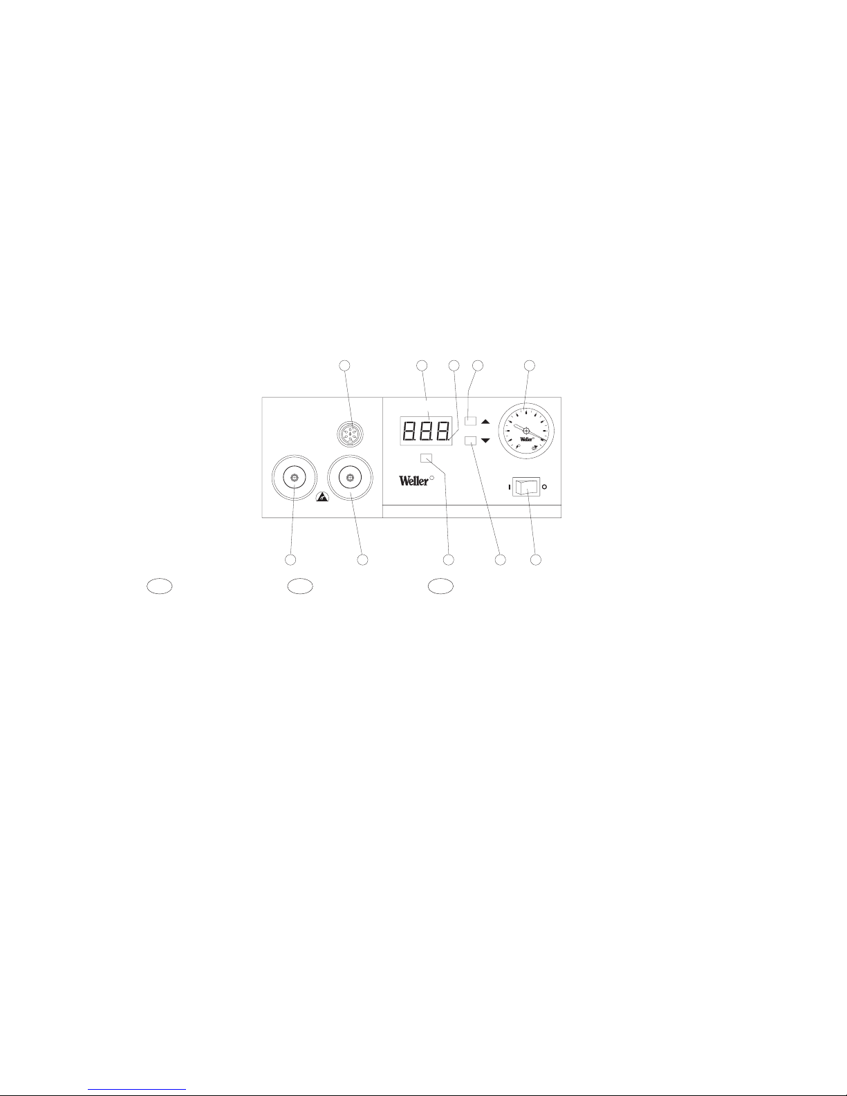
1. Connecting socket for soldering tool
2. Display
3. Dot for visual check on regulation
4. „Up“ button (increasing the set value)
5. Vacuum display
6. Mains switch
7. „Down“ button (decreasing the set
value)
8. „Air“ button for setting the air volume
9. Vacuum filter
10. Air filter
1. Prise pour outil de soudage
2. Afficheur
3. Témoin lumineux de contrôle optique
du réglage
4. Touche "Up" (augmente la valeur
réglée)
5. Indicateur de dépression
6. Interrupteur général
7. Touche "Down" (réduit la valeur
réglée)
8. Touche "Air" pour le réglage de
la quantité d'air
9. Filtre vide
10.Filtre air
1. Conector hembra para soldador
2. Visor
3. Punto luminoso para control óptico
de régula
4. Tecla Up (aumenta el valor)
5. Display de vacío
6. Interruptor de red
7. Tecla Down (disminuye el valor)
8. Tecla Air para seleccionar la cantidad
de aire
9. Filtro de vacío
10.Filtro de aire
GB F E
Air
WRS
1002
Repair System
ESD SAFE
bar
0,2
0,40,6
0,8
-1
0
Vac
Air
4D9R782
1
245
6
8
79
10
3
R
R
2
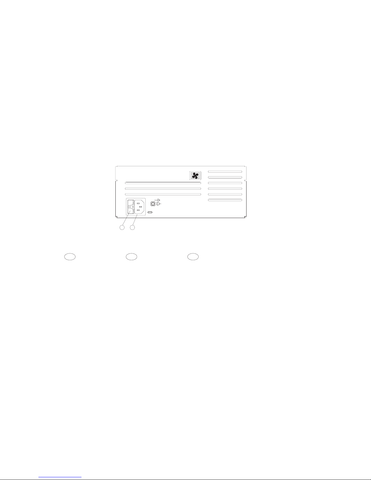
11.Mains fuse 5 x 20
12.Mains connection
11.Fusible secteur 5 x 20
12.Connecteur secteur
11.Fusible
12.Conexión a red
GB F E
1211
120V
T1,6A
4D9R783

3
1. Description
The WRS 1002 is a solder / desolder unit, which has an outstanding range of
functions. All the soldering attachments listed in the accessories list (25 W-150 W)
may be connected alternately. Adjustment of the different soldering devices is not
necessary since the integrated microprocessor automatically recognises the
connected device and optimises the relevant parameters for optimum control. The
temperature is controlled digitally. The required process parameters for temperature
and air are entered via three user-friendly buttons (Up, Down, Air). Set value and
actual value are displayed digitally.
With the hot air pencil temperatures of 150°F – 1000°F can be realised, on the
connection of a soldering iron or desoldering iron the adjustment range is
automatically limited to max. 850°F. The achievement of the pre-selected temperature
is indicated by a flashing dot on the display. Continuous illumination signifies that the
system is warming up. The air for the hot air pencil and the vacuum for the
desoldering iron are generated using an internal pump and activated using a
microswitch on the soldering tool.
Various timing functions for the soldering tools and a lock function (keylock) for the
process parameters can be set using the WCB1 and WCB2 external data input units.
A wide range of products including hot-air jets, suction nozzles and soldering bits are
available which allow many different soldering tasks to be undertaken.
The metal casing is anti-static coated. The soldering tip is hard grounded.
Spezifications
Dimensions (W x D x H): 240 x 270 x 105 mm
Mains voltage (12): 120 V, 60 Hz
Power consumption: 175 W
Safety class: 1 and 3
Fuse (11): (T1,6A) 5 x 20
Temperature control: solder / desolder: 150°F – 850°F
hot-air pencil: 150°F – 1000°F
WSP 150: 150°F – 1000°F
Pump
duty cycle (30/30) sec: max. capacity 20 l/min (hot-air 10 l/min)
max. vacuum 0,7 bar
2. Installation
Place the soldering bit in the safety holder. Connect the connecting cable on the
control instrument.
Plug in, and latch the electrical connector on the 7 terminal connector (1).
For the hot-air pencil: Push the air hose onto the „air“ nipple (10).
For desoldering: Push the vacuum hose onto the „vac“ nipple (9).
Attention: To avoid injury, the vacuum hose of the desolderer should never be
connected to the „air“ nipple.
Check whether the mains voltage matches the information on the rating plate. In the
case of correct mains voltage, connect the controller to the mains (12). Switch on unit
at the mains switch (6). When the unit is switched on a self-test is performed during
which all display elements (2) are operated briefly. The electronics then switches
automatically to the temperature and air flow rate set. The red dot on the display (3)
illuminates. This dot is used as visual check on the regulation. Continuous
illumination signifies that the system is warming up. Flashing signals that the preselected temperature has been reached. The temperature display (2) indicates the
actual value.
The built-in pump is started using a microswitch that is integrated in the handle.
The supply unit uses a pressure gauge (5) to display the vacuum. The degree of
contamination of the filter cartridge (9) is displayed here.
Attention: The pump motor is fitted with a ventilator to ensure that the instrument
remains cool. There must be sufficient air supply for this ventilator.
Setting the temperature
In general the digital display (2) shows the actual temperature. By pressing the „Up“
or „Down“ button (4) (7), the display (2) switches to the set value. This value can then
be increased or decreased by pressing the „Up“ or „Down“ button (4) (7) respectively.
GB

4
If the button is continuously pressed, the adjustment is fast. Approx. 2 sec. after
releasing the button, the display (2) automatically switches back to showing the actual
temperature. Dependent on the system, when using the hot-air pencil only the set
value is displayed.
Air-setting
By permanently pressing the „Air“ button (8) the display switches to air-volume. The
air throughput can then be altered gradually from 1 l/min-10 l/min by pressing the
„Up“ or „Down“ buttons (4) (7). If the buttons are continuously pressed, the
adjustment is fast.
Offset / Setback Adjustment (Temperature Compensation / Temperature Reduction)
Switch off unit. Keep „UP“ button pressed during switch on until the self-test has
been completed. Release button. The offset value currently set appears on the display
to the right of the digital point. When the „Air“ button is pressed the display to the left
of the digital point changes to the setback value. These values can be changed using
the „UP“ or „DOWN“ button.
To save the value set, keep the „AIR“ button pressed until the display flashes.
Maintenance
When using the hot-air pencil:
Contaminated filters influence the air throughput of the pump. Therefore the main
filters for „vacuum“ (9) and „air“ (10) should be inspected regularly and changed
when necessary. To do this, unscrew the filter cover, remove the contaminated filter
and replace with a new original Weller filter cartridge. Make sure that the filter-cover
seal is correctly in place, insert the compression spring, and screw the filter cover
back on firmly.
When using the desolder:
Desoldering bit, heating element and sensor make up a single unit which is highly
efficient. The desolderer should be cleaned regularly. This involves emptying the
solder collector, changing the glass tube filter and checking the seals. A perfect seal
of the face of the glass cylinder gives full section power. Contaminated filters influence
the air throughput of the pump. Therefore the main filters for „vacuum“ (9) and „air“
(10) should be inspected regularly and changed when necessary. To do this, unscrew
the filter cover, remove the contaminated filter and replace with a new original Weller
filter cartridge. Make sure that the filter cover seal is correctly in place, insert the
compression spring, and screw the filter cover back on firmly. The „vacuum“ filter
removes flux vapours from the extracted air and must therefore be regularly
inspected.
Attention: Working without the filter destroys the vacuum pump.
Use the cleaning tool (0051350099) to clean the suction nozzle opening and the
suction tube.
Various suction nozzles solve many desoldering problems. The suction nozzles can
be changed easily; a suitable tool is integrated into the cleaning tool. The thread on
new suction nozzles should be smeared with „Antilocking paste”.
Only change suction nozzles when hot.
To avoid the suction nozzle seizing solid with the heat, the suction nozzle should be
unscrewed regularly and the thread smeared with „Antilocking paste”.
In the case of a very dirty thread or a broken suction nozzle, the repair can be
performed as follows:
1. Drill out with 4 mmø drill, maximum 11 mm deep.
2. Recut the thread with an 12 – 24 UNC 2A tap, remove swarf.
3. Smear new suction nozzle with antilocking paste and screw in place.
Figures of the cleaning tools, cleaning procedure and exchange of the suction
nozzles see page 20.
3. Information for Operation
Hot-air pencil:
The nozzles are screwed onto the heating element. To change the nozzles use the
socket spanner SW 8 and a wrench.
Attention: The thread length is at most 5 mm. A longer thread destroys the heating
element.

5
Desoldering iron:
When desoldering, it is important to use additional solder wire. This gives good
wetting of the suction nozzles and better flow properties of the old solder. Care should
be taken that the suction nozzle is perpendicular to the circuit board in order to
achieve the optimum suction power. The solder must be completely fluid. During
desoldering it is important to move the connecting pin of the component in circular
movements in the hole. If the solder is not completely removed after the suction
process, the soldered joint should be newly tinned before the next attempt at
desoldering.
It is important to choose the correct size of suction nipple. Rule of thumb is that the
inner diameter of the suction nozzle should be the same as the diameter of the circuit
board hole.
Pump over-run when using the vacuum function
When desoldering, the vacuum function can be set to continue running (1 sec.). The
factory setting does not active this over-run.
Switching on the pump over-run
Turn of the instrument. Press the „up“ and „down“ buttons when turning the
instrument back on, until the self-test is finished. A „-1-“ will appear on the display.
Release the buttons.
Switching off the pump over-run
Turn of the instrument. Press the „up“ and „down“ buttons when turning the
instrument back on, until the self-test is finished. A „OFF“ will appear on the display.
Release the buttons.
Soldering:
When heating up for the first time, the soldering bit should be wetted with solder. This
removes oxide layers and contamination which might have occurred during storage.
When pausing between soldering, and before putting the soldering iron down, ensure
that the bit is well tinned. Do not use very aggressive flux.
Attention: Never use the soldering iron without a bit, as this will damage this
heating element and temperature sensor.
General: The soldering irons are set for medium bits and nozzles. Deviations caused
by changing the bits, or by using other types of bits can occur.
4. Safety information
The manufacturer accepts no liability for usage other than that specified in the
operating instructions, nor for any unauthorised modifications.
These operating instructions and the warning instructions they contain should be read
carefully and kept in a clearly visible place adjacent to the soldering unit. Failure to
adhere to warning instructions can cause accidents and injuries or be detrimental to
health.
5. Accessories
5 33 125 99 Soldering set WSP 80
5 33 131 99 Soldering set MPR 80
5 33 112 99 Soldering set LR 21 antistatic
5 33 113 99 Soldering set LR 82
5 33 155 99 Soldering set WMP
5 33 134 99 Desoldering set DS VT 80
5 33 121 99 Desoldering set DS 80 UNC
5 33 129 99 Desoldering set DSV 80 UNC
5 33 133 99 Desoldering set WTA 50
5 33 135 99 Soldering Iron Set WSP 150
5 33 114 99 Hot Air Soldering Iron Set HAP 1
5 27 040 99 Solder Bath WSB 80
5 27 028 99 Preheater plate WHP 80
5 31 181 99 External input unit WCB 1
5 31 180 99 External input unit WCB 2
WPHT Stop and go iron stand (WMP)
WPH80T Stop and go iron stand (WSP 80)
6. Scope of delivery
 Loading...