

Weller WR 3ME Operating Instructions Manual
WR 3ME
Operating Instructions - Istruzioni per lùso - Manual de uso

EN
FR
IT
ES
PT
NL
SV
DK
FI
GR
TR
CZ
PL
HU
SK
SL
EE
LV
LT
EN
WR 3ME
Operating Instructions
WR 3ME
WR 3ME
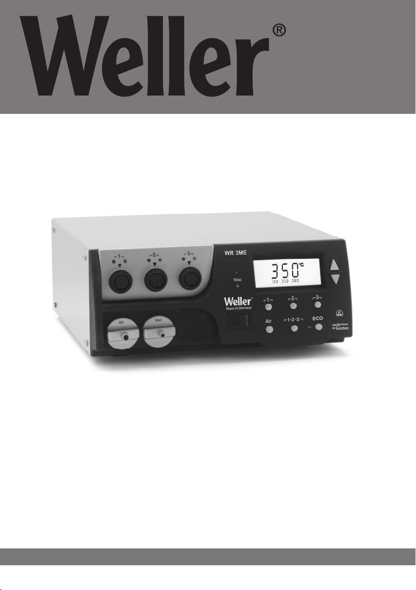
Equipment overview
1 LED channel selection
2 LED optical control indicator
3 LED vacuum
4 Display
5 UP button
6 DOWN button
7 Channel selection /
temperature buttons
┌ 1 ┐, ┌ 2 ┐, ┌ 3 ┐
8 ECO
9 Status display LED
ECO
10 Temperature button ┌ 1·2·3 ┐
channel selection
11 Hot-air setting button (Air)
12 Mains power switch
13 Connection, vacuum (Vac)
14 Connection, hot air (Air)
15 Connector sockets, soldering
tool channel
┌ 1 ┐, ┌ 2 ┐, ┌ 3 ┐
16 Temperature display
17 Temperature symbol
18 Time functions
19 Lock
20 Optical control check
21 Display, channel selection
22 Display, fixed temperature
23 Display, special functions
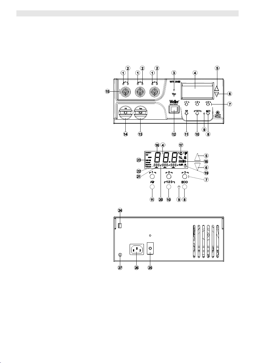
24 USB port
25 Mains system fuse
26 Mains system connection
27 Equipotential-bonding socket

WR 3ME 3-22
EN
EN
FR
IT
ES
PT
NL
SV
DK
FI
GR
TR
CZ
PL
HU
SK
SL
EE
LV
LT
Contents
1 About these instructions ........................................................... 3
2 For your safety ......................................................................... 4
3 Scope of delivery ..................................................................... 4
4 Device description.................................................................... 5
5 Starting up the device .............................................................. 7
6 Operating the device ................................................................ 8
7 Special functions ...................................................................... 10
8 Resetting to factory settings ..................................................... 19
9 Care and maintenance of the WR 3ME .................................... 19
10 Fault messages and fault elimination ....................................... 20
11 Accessories ............................................................................. 21
12 Disposal ................................................................................... 22
13 Warranty .................................................................................. 22
1 About these instructions
Thank you for the confidence you have shown in buying the
Weller WR 3ME. Production was based on stringent quality
requirements which guarantee the perfect operation of the device.
These instructions contain important information which will help you
to start up, operate and service the WR 3ME repair station safely
and correctly as well as to eliminate simple faults/malfunctions
yourselves.
Read these instructions and the accompanying safety information
carefully before starting up the device and starting work with the
WR 3ME repair station.
Ensure that these instructions are accessible to all users.
1.1 Directives taken into consideration
The Weller microprocessor-controlled repair station WR 3ME
complies with the specifications of the EC Declaration of Conformity
based on Directives 2004/108/EC, 2006/95/EC and 2011/65/CE
(RoHS).
1.2 Documents also applicable
Operating Instructions for the repair station WR 3ME
Safety information booklet accompanying these instructions

4-22 WR 3ME
DE
EN
FR
IT
ES
PT
NL
SV
DK
FI
GR
TR
CZ
PL
HU
SK
SL
EE
LV
LT
2 For your safety
The WR 3ME repair station has been manufactured in accordance
with state-of-the-art technology and recognised safety rules and
regulations. There is nevertheless the risk of personal injury and
damage to property if you fail to observe the safety information set
out in the accompanying booklet and the warnings given in these
instructions. If the repair station WR 3ME is passed on to third
parties, always hand over the Operating Instructions as well.
2.1 Specified use
Always use the repair station WR 3ME exclusively for the purpose
specified in the Operating Instructions, namely soldering under the
conditions specified here. Intended use of the WR 3ME repair station
also includes the requirement that
observing these operating instructions,
observing all other accompanying documentation,
observance of the locally applicable accident prevention
regulations.
The manufacturer shall not be liable for damage resulting from
unauthorised alterations to the machine.
3 Scope of delivery
WR 3ME repair station
Power cable
Air-hose adapter for hot-air pencil 1 (HAP 1)
CD with USB software (“Firmware Updater” and
“Monitor Software”)
Equipotential-bonding connector

WR 3ME 5-22
EN
EN
FR
IT
ES
PT
NL
SV
DK
FI
GR
TR
CZ
PL
HU
SK
SL
EE
LV
LT
4 Device description
The Weller WR 3ME is a versatile repair station for making
professional repairs to latest-technology electronic subassemblies in
industrial production engineering and in the repair and laboratory
fields. The WR 3ME has 3 independent channels for simultaneously
operating 3 soldering tools.
Precise temperature control performance at the soldering tip is
guaranteed by the digital control electrotechnology together with
superior-quality sensor and heat-transfer technology. High-speed
measured-value acquisition provides for maximum temperature
precision and optimum dynamic temperature performance in load
situations. The temperature can be set to any value within the range
from 50 °C to 550 °C (150 °F – 999 °F) depending on which tool is
connected. Setpoint and actual values are displayed in digital form.
Three temperature buttons are used to select fixed temperatures
directly. The optical control indicator flashes ("“ symbol in the
display and additional green LED) to indicate when the preselected
temperature has been reached.
The Weller WR 3ME repair station offers the following additional
functions:
Automatic tool detection and activation of corresponding control
parameters
All Weller tools incl. HAP 200 can be connected
(WX tools excluded)
Digital temperature control
Option of inputting offset values
Programmable temperature reduction (setback)
Standby and lock functions
Installed heavy-duty pump
Antistatic device design in accordance with ESD safety
Different equipotential-bonding possibilities on the device
(standard configuration)
Customer-specific calibration function
USB port for control, evaluation and documentation via PC

6-22 WR 3ME
DE
EN
FR
IT
ES
PT
NL
SV
DK
FI
GR
TR
CZ
PL
HU
SK
SL
EE
LV
LT
Dimensions
L x W x H (mm): 273 x 235 x 102
L x W x H (inches):
10.75 x 9.25 x 4.02
Weight
approx. 6.7 kg
Mains supply voltage
230 V, 50 Hz (120 V, 60 Hz)
Power consumption
400 W
Safety class
I and III, housing antistatic
Fuse
Overcurrent release 230 V 2.0 A
120 V 4.0 A
Temperature control of
channels
Soldering and desoldering iron
stepless 50 °C – 550 °C
(150 °F – 999 °F)
Controllable temperature range
depends on the tool.
WP 65
100 °C – 450 °F (212 °F – 850 °F)
WP 80 / WP 120
50 °C-450 °C (150 °F-850 °F)
WSP 150
50 °C-550 °C (150 °F-950 °F)
WP 200
50 °C-550 °C (150 °F-950 °F)
WMRT / WMRP
100 °C-450 °C (200 °F-850 °F)
DSX 80 / DXV 80
50 °C-450 °C (150 °F-850 °F)
DSX 120
50 °C-450 °C (150 °F-850 °F)
HAP 200 / HAP 1
50 °C-550 °C (150 °F-999 °F)
Temperature accuracy
9 °C ( 17 °F)
Temperature stability
2 °C (4 °F)
Soldering tip leakage
resistance (tip to ground)
Corresponds to IPC-J-001
Soldering tip leakage
current (tip to ground)
Corresponds to IPC-J-001
Pump (periodic duty
(30/30) s)
Max. vacuum 0.7 bar
Max. delivery rate 18 l/min
Hot air max. 15 l/min
Potential balance
Via 3.5 mm pawl socket on back of
device
4.1 Technical data WR 3ME
WR 3ME 7-22
EN
EN
FR
IT
ES
PT
NL
SV
DK
FI
GR
TR
CZ
PL
HU
SK
SL
EE
LV
LT
WARNING!
Risk of injury due to incorrectly connected vacuum
hose.
If the vacuum hose is incorrectly connected, hot air and liquid
solder can escape when the unsoldering bit is actuated and cause
injuries.
Never connect the vacuum hose to the "Air“ nipple!
Note
If you are using an HAP 200, this can only be connected to
channel 1! The maximum output power is limited to 360 watts.
USB port
The control unit is equipped with a mini USB port (24). For the
purpose of using the USB port, Weller software is available on a CD
with which you
can carry out a software update ("Firmware Updater“) on your
control unit and
can remote-control the control unit and graphically display, store
and print temperature curves ("Monitor Software“).
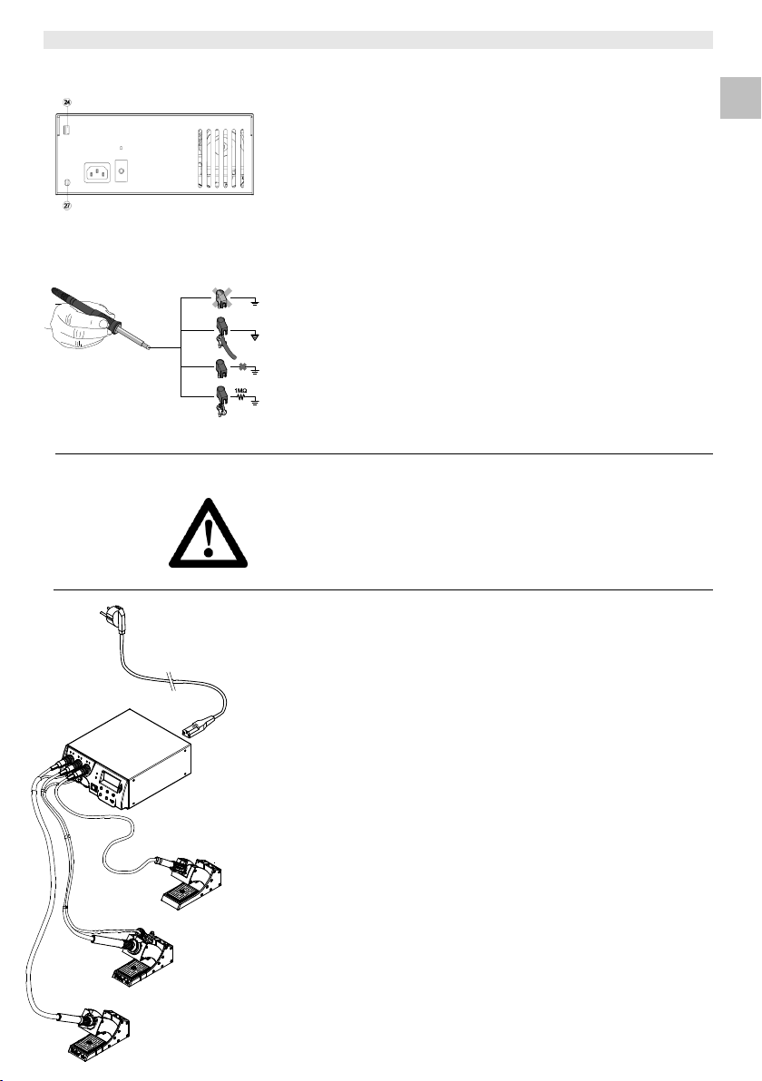
Equipotential bonding
4 variants are possible through connecting the 3.5 mm pawl
socket (27) differently:
Hard earthed/grounded: without connector (delivery status)
Equipotential bonding: with connector, bonding lineat central
contact
Floating: with connector
Soft earthed/grounded: with connector and soldered resistor.
Earthing/grounding via the selected resistor
5 Starting up the device
1. Carefully unpack the device.
2. Connect the soldering tools as follows:
- Connect the hot-air pencil (HAP) with air hose to "Air“
nipple (14) and insert with the attachment plug in connection
socket ┌ 1 ┐, ┌ 2 ┐ or ┌ 3 ┐ (15) of the repair station and lock by
turning clockwise slightly. The HAP 1 hot-air pencil can only be
connected with the air-hose adapter.
- Connect the unsoldering tool with vacuum hose to "Vac“
nipple (13) and insert with the attachment plug in connection
socket ┌ 1 ┐, ┌ 2 ┐ or ┌ 3 ┐ (15) of the repair station and lock by
turning clockwise slightly.
- Insert the soldering tool with attachment plug in connection
socket ┌ 1 ┐, ┌ 2 ┐ or ┌ 3 ┐ (15) of the repair station and lock by
turning clockwise slightly.
3. Place the soldering tools in the safety holder.
4. Check whether the mains supply voltage matches that indicated
on the rating plate and whether mains power switch (12) is off.
5. Connect the control unit to the mains supply (26).
6. Switch on the device at mains power switch (12).
8-22 WR 3ME
DE
EN
FR
IT
ES
PT
NL
SV
DK
FI
GR
TR
CZ
PL
HU
SK
SL
EE
LV
LT
Note
The display switches automatically to the channel to which a tool
has been newly connected, the finger switch has been pressed or
the tool has been removed from the switching holder.
This function can be deactivated in the special functions menu 2
(see "Deactivate / activate automatic channel change" on page 18).
After the device has been switched on, the microprocessor carries
out a self-test in which all the segments are briefly in operation. Then
the electronics switches automatically to the basic temperature
setting of 350 °C for all channels and 50 % for the "Air" setting.
Green LED (2) lights up when activated channels are being used:
LED lit green constantly indicates that the connected tool is being
heated up.
LED flashing green indicates that the preselected tool temperature
has been reached.
Active channels are indicated in the display with a triangle (21) and a
lightning symbol (20).
6 Operating the device
6.1 Selecting a channel, switching on or off
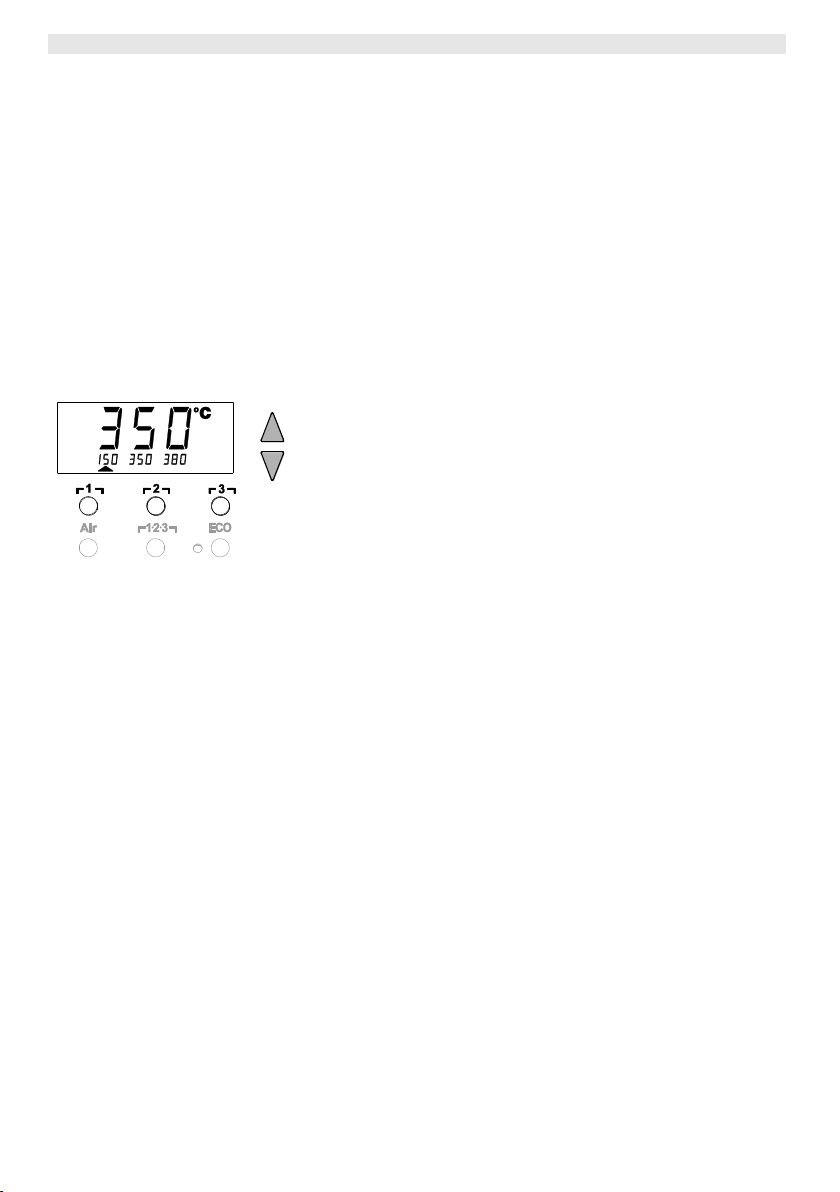
1. Press one of the buttons ┌ 1 ┐, ┌ 2 ┐ or ┌ 3 ┐ to select one of the
three channels.
The display shows the setpoint temperature of the selected
channel and - in smaller script - the permanently programmed
temperatures.
- Or Tap on the ┌ 1·2·3 ┐button until the desired channel is displayed.
The current tool temperature then appears in the display. The
status with the corresponding setpoint temperature is also
displayed in the lower area.
The selected channel is indicated by a triangle (20) in the display
and by a red-lit LED (1) on the device.
2. Press the UP and DOWN buttons simultaneously until three
dashes "- - -“ appear in the display.
3. Release the buttons.
If the channel is now deactivated, "OFF“ appears in the display.
If the channel is activated, the current actual temperature
appears in the display.
Stored data are not lost when a channel is switched off.
WR 3ME 9-22
EN
EN
FR
IT
ES
PT
NL
SV
DK
FI
GR
TR
CZ
PL
HU
SK
SL
EE
LV
LT
Note
Assigning a low "Setback“ temperature to a temperature button
offers the possibility of manual temperature reduction when the
soldering bit is not in use.
6.2 Setting the temperature
Setting the temperature individually
1. Select the desired channel by pressing one of the buttons ┌ 1 ┐,
┌ 2 ┐ or ┌ 3 ┐.
The display shows the actual temperature values of the selected
channel.
2. Press the UP or DOWN button.
The display switches to the set setpoint value. The temperature
symbol (17) flashes.
3. Press the UP or DOWN button to set the desired setpoint
temperature:
- Brief touching alters the setpoint value by one degree.
- Permanent pressing alters the setpoint value in rapid pass
mode.
The actual value of the selected channel appears in the display
again approx. 2 seconds after the setting buttons are released.
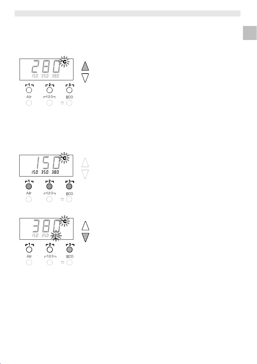
Setting temperature with temperature buttons ┌ 1 ┐, ┌ 2 ┐ and┌ 3 ┐
The setpoint temperature value can be set for each channel
separately by selecting three preset temperature values (fixed
temperatures).
Factory settings:
┌ 1 ┐ = 150 °C (300 °F), ┌ 2 ┐ = 350 °C (662 °F),
┌ 3 ┐ = 380 °C (716 °F)
1. Select a channel.
3 fixed temperatures are shown in the display for approx. 2 s.
The temperature value can now be input as long as the
temperature symbol is flashing.
2. Set the setpoint temperature value with the UP or DOWN button.
3. Keep the desired temperature button ┌ 1 ┐, ┌ 2 ┐ or ┌ 3 ┐
pressed for 3 seconds.
The temperature display for the corresponding temperature value
flashes during this period. The set value is stored after
3 seconds.
4. Release the temperature button again.
Selecting temperature with temperature buttons ┌ 1 ┐, ┌ 2 ┐ and
┌ 3 ┐
1. Select a channel.
2. Three fixed temperatures shown in the display for approx. 2 s.
As long as the temperature symbol is flashing, the desired
temperature can be selected by pressing ┌ 1 ┐, ┌ 2 ┐ or ┌ 3 ┐.
10-22 WR 3ME
DE
EN
FR
IT
ES
PT
NL
SV
DK
FI
GR
TR
CZ
PL
HU
SK
SL
EE
LV
LT
2 s ➾
Menu 1
4 s ➾
Menu 2
1x ➾
ON/OFF
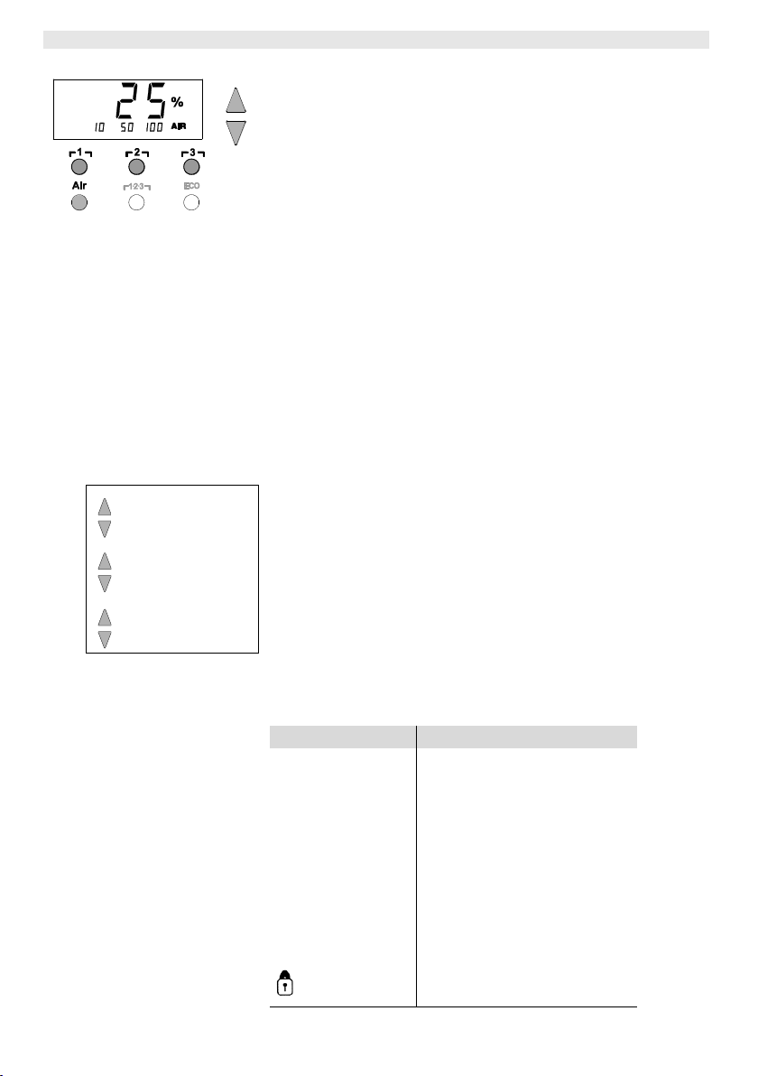
Note
Just as with the 3 fixed temperatures, 3 fixed air volumes can be set
and selected.
Factory settings:
┌ 1 ┐ = 10 %, ┌ 2 ┐ = 50 %, ┌ 3 ┐ = 100 %
Special functions
Navigation
STANDBY
↑
↓
EXIT
CH changing
┌ 1 ┐
┌ 2 ┐
┌ 3 ┐
┌ 1·2·3 ┐
SETBACK
AUTO OFF
OFFSET
WINDOW
°C/°F
ON TIME
VAC OFF
VAC ON
6.3 Setting air flow
The air flow can, starting from a maximum flow value of 15 l/s
(HAP 200) or 10 l/s (HAP 1), be set in a range of 10 % to 100 %.
1. Press the AIR button.
The current air flow in per cent is shown in the display for approx.
2 s.
2. Set the desired flow by pressing the UP or DOWN button.
The set value is adopted. The actual temperature of the selected
channel is displayed again after 3 s.
6.4 Soldering and unsoldering
Carry out the soldering work in accordance with the operating
instructions of your connected soldering tool.
7 Special functions
The special functions are divided into 2 menu levels:
Menu 1 with setting options for
standby temperature, temperature deactivation (setback),
automatic switch-off time (Auto-OFF), temperature offset, window
function, temperature units, switch-on time (On Time) for hot-air
pencil, vacuum OFF delay (VAC OFF), vacuum ON delay (VAC
ON) and lock function.
Menu 2 with setting options for
pressure gauge level, ID code, calibration function (FCC), autom.
channel change ON / OFF, button lock ON/OFF and control
characteristic HI / LO.
7.1 Selecting Menu 1 special functions
WR 3ME 11-22
EN
EN
FR
IT
ES
PT
NL
SV
DK
FI
GR
TR
CZ
PL
HU
SK
SL
EE
LV
LT
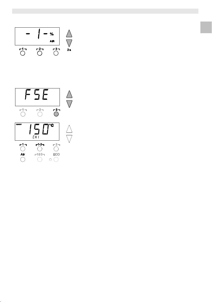
1. Select the desired channel ┌ 1 ┐, ┌ 2 ┐ or ┌ 3 ┐ for entering the
special functions.
2. Press and hold down the UP and DOWN buttons simultaneously.
"– 1 –“ appears in the display after 2 s.
3. Release the buttons.
Selection of the special functions of Menu 1 is activated.
The settings can now be made.
- Select menu items with buttons ┌ 1 ┐, ┌ 2 ┐.
- Exit the menu again with button ┌ 3 ┐ (EXIT).
- Change channel using the AIR (11) button.
Resetting the special functions to the factory settings
1. Press and hold down button ┌ 3 ┐.
2. Then press the UP and DOWN buttons simultaneously.
"FSE“ appears in the display.
The repair station is now reset to the factory settings.
Setting the standby temperature
The standby temperature is automatically set after a temperature
deactivation. The actual temperature flashes in the display.
"STANDBY“ appears in the display.
1. Select the menu item STANDBY in Menu 1.
2. Set the setpoint value for the standby temperature with the UP or
DOWN button.
3. Proceed to the next menu item with the button ┌ 1 ┐ (back) or
┌ 2 ┐ (forward).
12-22 WR 3ME
DE
EN
FR
IT
ES
PT
NL
SV
DK
FI
GR
TR
CZ
PL
HU
SK
SL
EE
LV
LT
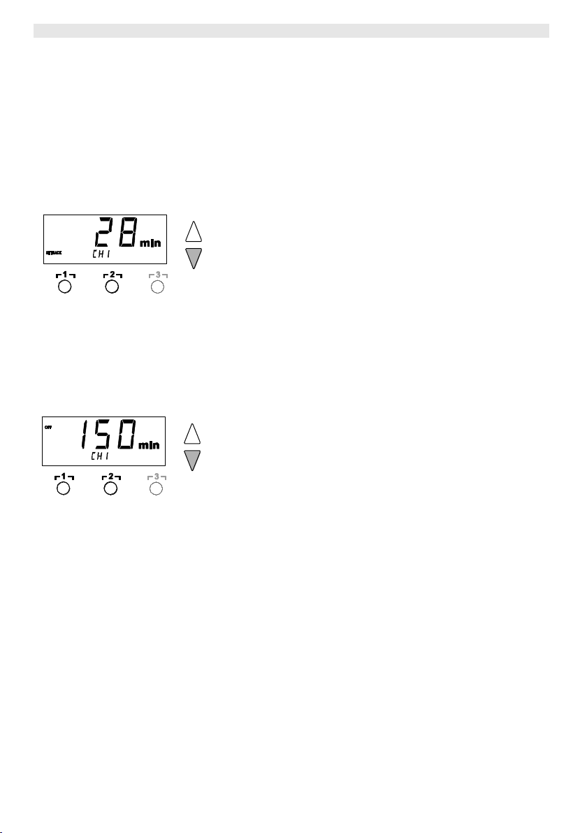
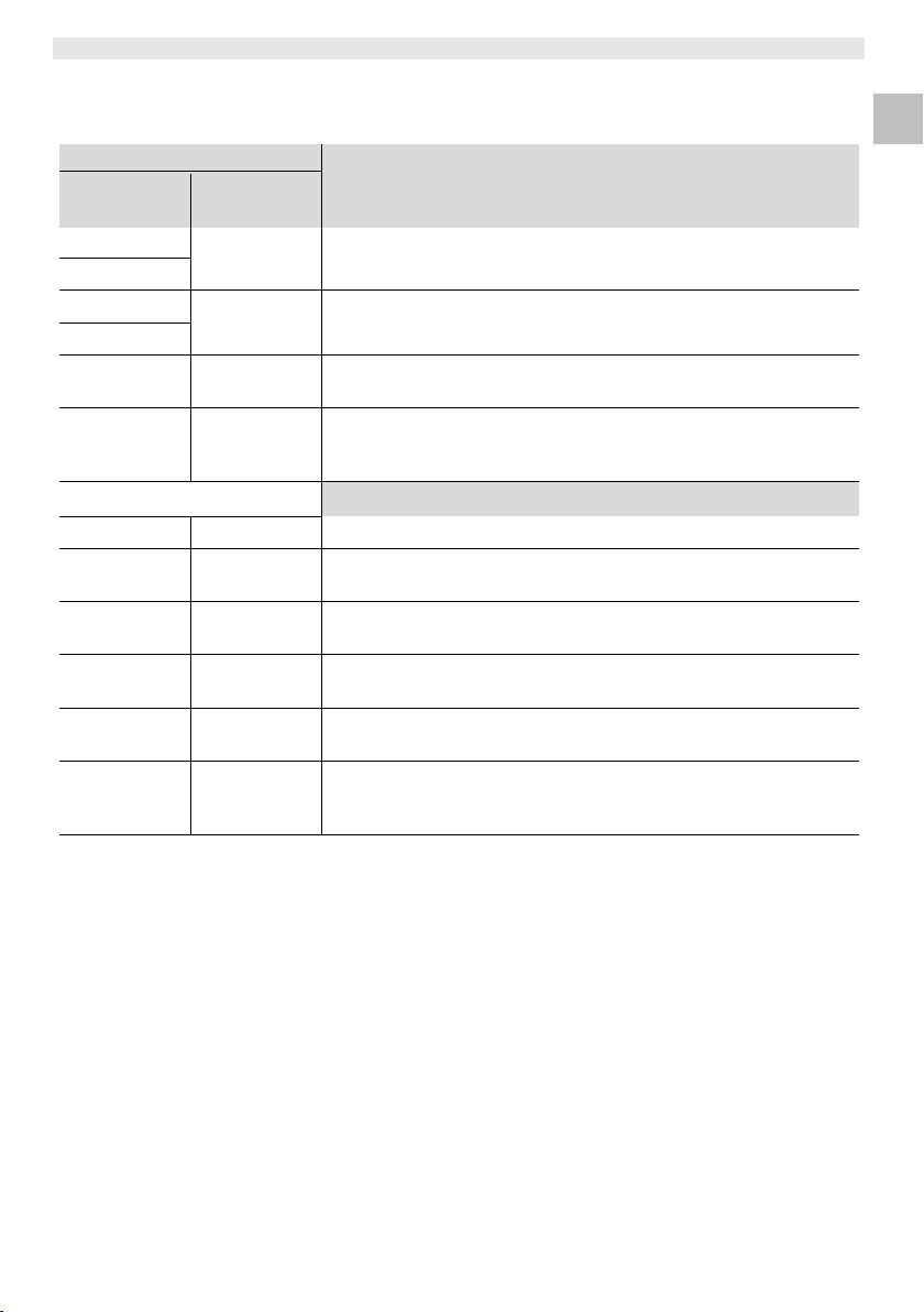
Setting temperature deactivation (SETBACK)
When the soldering tool is not in use, the temperature is reduced to
the standby temperature after the set setback time has elapsed. The
setback state is indicated by a flashing actual value and "STANDBY“
appears in the display. Pressing the UP or DOWN button terminates
this setback state. Depending on the tool, the finger switch or the
switching holder deactivates the setback state.
The following setback settings are possible:
"0 min“: setback OFF (factory setting)
"ON“: setback ON (the system is controlled down to standby
temperature with the switching holder after the soldering bit is
stowed)
"1-99 min“: setback ON (individually settable setback time)
1. Select the menu item SETBACK in Menu 1.
2. Set the setback value with the UP or DOWN button.
3. Proceed to the next menu item with the button ┌ 1 ┐ (back) or
┌ 2 ┐ (forward).
Setting the automatic switch-off time (AUTO-OFF)
When the soldering tool is not in use, heating of the soldering
tool is switched off after the AUTO-OFF time has elapsed.
Temperature deactivation is performed independently of the set
setback function. The actual temperature flashes in the display and
serves as residual-heat indicator. "OFF“ appears in the display.
Below 50 °C (122 °F), a flashing dash appears in the display.
The following AUTO-OFF time settings are possible:
"0 min“: AUTO-OFF function is switched off
"1-999 min": AUTO-OFF time, individually settable
1. Select the menu item OFF in Menu 1.
2. Set the AUTO-OFF setpoint time value with the UP or DOWN
button.
3. Proceed to the next menu item with the button ┌ 1 ┐ (back) or
┌ 2 ┐ (forward).
WR 3ME 13-22
EN
EN
FR
IT
ES
PT
NL
SV
DK
FI
GR
TR
CZ
PL
HU
SK
SL
EE
LV
LT
Settings
Temperature performance without switching holder
SETBACK time
[1-99 mins]
OFF time
[1-999 mins]
0
0
Soldering tool remains at the set soldering temperature.
ON
0
Time
Soldering tool is switched off when not in use1) after the OFF time
has elapsed.
ON
Time
0
Soldering tool is controlled down when not in use1) to the STANDBY
temperature2) after the SETBACK time has elapsed.
Time
Time
Soldering tool is controlled down when not in use1) to the STANDBY
temperature2) after the SETBACK time has elapsed and is switched
off after the OFF time has elapsed.
Temperature performance with switching holder
0 0 Soldering is switched off in the holder3).
ON
0
Soldering tool is controlled down in the holder3) to the STANDBY
temperature2).
0
Time
Soldering tool is switched off in the holder3) after the OFF time has
elapsed.
ON
Time
Soldering tool is controlled down in the holder3) to the STANDBY
temperature2) and is switched off after the OFF time has elapsed.
Time
0
Soldering tool is controlled down in the holder3) to the STANDBY
temperature2) after the SETBACK time has elapsed.
Time
Time
Soldering tool is controlled down in the holder3) to the STANDBY
temperature2) after the SETBACK time has elapsed and is switched
off after the OFF time has elapsed.
1)
Not in use = UP/DOWN buttons not pressed and no temperature drop > 5 °C.
2)
STANDBY temperature must be below the set setpoint temperature, otherwise the SETBACK
function is inactive.
3)
When a switching holder is connected, the soldering tool always remains at the set setpoint
temperature outside the holder.
The holder function is activated when the soldering tool is stowed for the first time.
Note
Reset of STANDBY and OFF modes:
without switching holder by pressing the UP or DOWN button.
with switching holder by removing the soldering tool from the
holder.
Temperature performance with different settings of the SETBACK
and AUTO OFF functions
14-22 WR 3ME
DE
EN
FR
IT
ES
PT
NL
SV
DK
FI
GR
TR
CZ
PL
HU
SK
SL
EE
LV
LT
Note
To be able to use the WINDOW function, ensure that the repair
station is in the locked state (see "Switching the lock function on/off“
Page 15).
Setting the temperature offset
The real soldering-tip temperature can be adapted by entering a
temperature offset around ± 40 °C (± 72 °F).
1. Select the menu item OFFSET in Menu 1.
2. Set the OFFSET temperature value with the UP or DOWN
button.
3. Proceed to the next menu item with the button ┌ 1 ┐ (back) or
┌ 2 ┐ (forward).
Setting the window function
It is possible, starting from a set, locked temperature, to set a
temperature window of ± 99 °C (± 180 °F) with the aid of the
WINDOW function.
1. Select the menu item WINDOW in Menu 1.
2. Set the WINDOW temperature value with the UP or DOWN
button.
3. Proceed to the next menu item with the button ┌ 1 ┐ (back) or
┌ 2 ┐ (forward).
Switching the temperature unit
Switching the temperature unit from °C to °F or vice versa.
1. Select the menu item °C / °F in Menu 1.
2. Set the temperature unit with the UP or DOWN button.
3. Proceed to the next menu item with the button ┌ 1 ┐ (back) or
┌ 2 ┐ (forward).
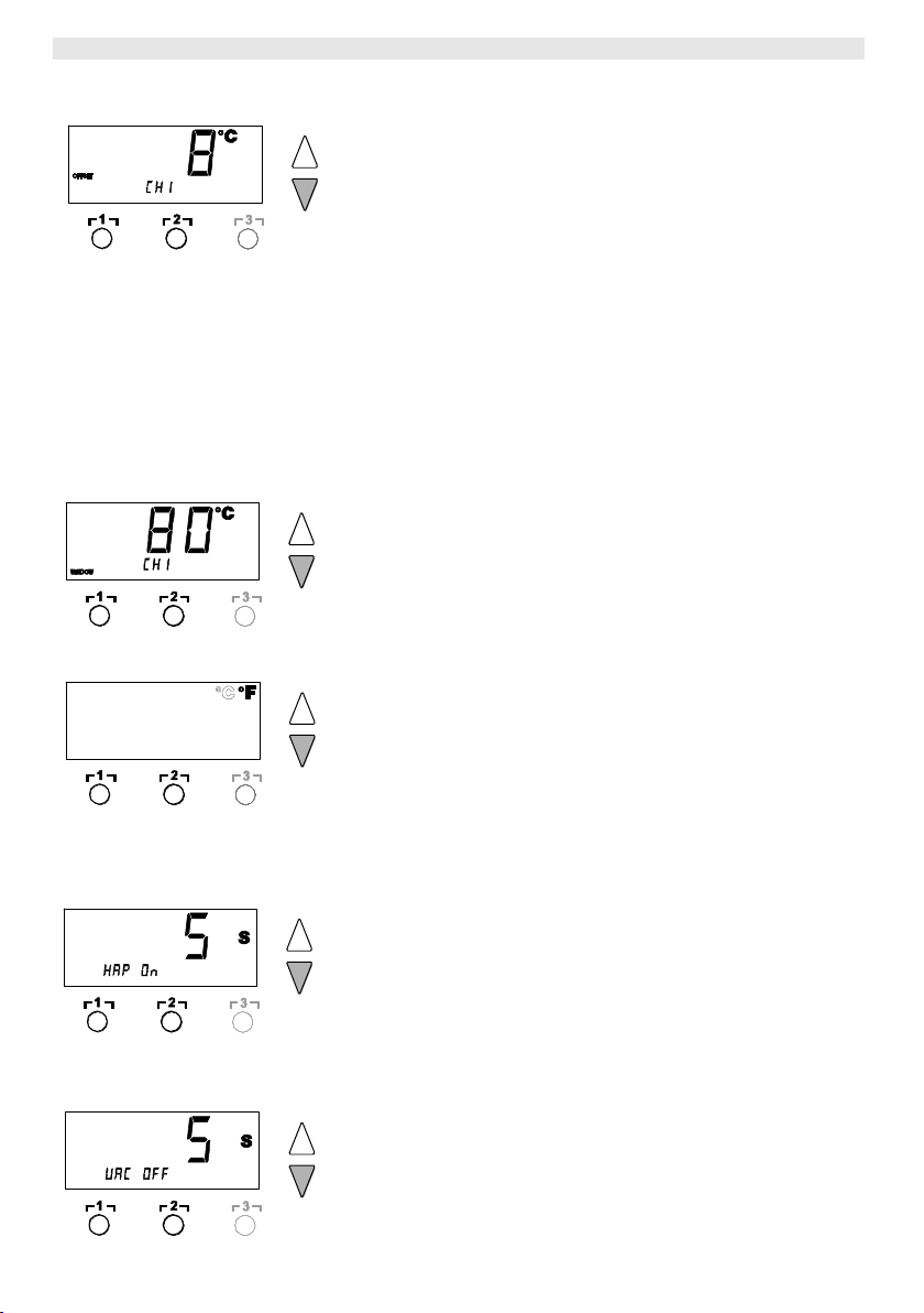
Limiting the switch-on time (ON TIME) for hot-air pencil (HAP)
The switch-on time for the HAP hot-air flow can be limited in
increments of 1 from 0 to 60 s. The set time is then identical for all 3
channels. Factory setting is 0 s ("OFF“), i.e. the air flow is activated
as long as the button on the hot-air pencil or the optional foot switch
is pressed.
1. Select the menu item HAP-TIME in Menu 1.
2. Set the time value with the UP or DOWN button.
3. Proceed to the next menu item with the button ┌ 1 ┐ (back) or
┌ 2 ┐ (forward).
Setting the vacuum OFF delay (VAC OFF)
To prevent the unsoldering bit from becoming clogged, it is possible
to set a vacuum OFF delay of 0 to 5 s (factory setting 2 s).
1. Select the menu item VAC OFF in Menu 1.
2. Set the time value (VAC OFF) with the UP or DOWN button.
3. Proceed to the next menu item with the button ┌ 1 ┐ (back) or
┌ 2 ┐ (forward).
WR 3ME 15-22
EN
EN
FR
IT
ES
PT
NL
SV
DK
FI
GR
TR
CZ
PL
HU
SK
SL
EE
LV
LT
Note
Pressing the buttons ┌ 1 ┐ or ┌ 2 ┐ while "OFF“ is displayed results
in the menu item being exited without a stored lock code.
Special functions
Navigation
LEVEL
↑
↓
EXIT
CH changing
┌ 1 ┐
┌ 2 ┐
┌ 3 ┐
┌ 1·2·3 ┐
ID
FCC
ECO
HAP LOCK
HI / LO CONTROL
AUTO CHANNEL
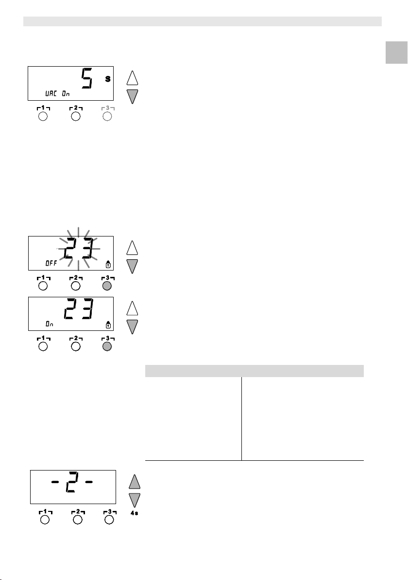
Setting the vacuum ON delay (VAC ON)
In order to prevent the pump from starting prematurely or to ensure a
defined soldering-joint preheating time, it is possible to set an ON
delay of 0 to 9 s (factory setting 0 s: Off).
1. Select the menu item VAC ON in Menu 1.
2. Set the time value (VAC ON) with the UP or DOWN button.
3. Proceed to the next menu item with the button ┌ 1 ┐ (back) or
┌ 2 ┐ (forward).
Switching the lock function on/off
After the lock is switched on, only the temperature buttons ┌ 1 ┐,
┌ 2 ┐ and ┌ 3 ┐, Pick-Up and ┌ 1·2·3 ┐ can still be operated on the
repair station. All other settings are disabled until the repair station is
unlocked again.
To lock the repair station:
1. Select the menu item LOCK in Menu 1.
"OFF“ appears in the display. The padlock symbol flashes.
2. Set a 3-digit lock code with the UP or DOWN button.
3. Press button ┌ 3 ┐ for 5 seconds.
The code is stored. The padlock symbol is displayed. The station
is now locked. The display switches to the main menu.
To unlock the repair station:
1. Select the menu item LOCK in Menu 1.
"ON“ appears in the display. The padlock symbol is displayed.
2. Enter the 3-digit lock code with the UP or DOWN button.
3. Press button ┌ 3 ┐.
The station is now unlocked. The display switches to the main
menu.
7.2 Selection special functions menu 2
1. Select the desired channel ┌ 1 ┐, ┌ 2 ┐ or ┌ 3 ┐ for entering the
special functions.
2. Press and hold down the UP and DOWN buttons simultaneously.
"– 2 –“ appears in the display after 4 s.
3. Release the buttons.
Selection of the special functions of Menu 2 is activated.
The settings can now be made.
Select menu items with buttons ┌ 1 ┐ and ┌ 2 ┐.
Exit the menu again with button ┌ 3 ┐ (EXIT).
16-22 WR 3ME
DE
EN
FR
IT
ES
PT
NL
SV
DK
FI
GR
TR
CZ
PL
HU
SK
SL
EE
LV
LT
Note
Press button ┌ 3 ┐ to exit the menu item without changes (EXIT).
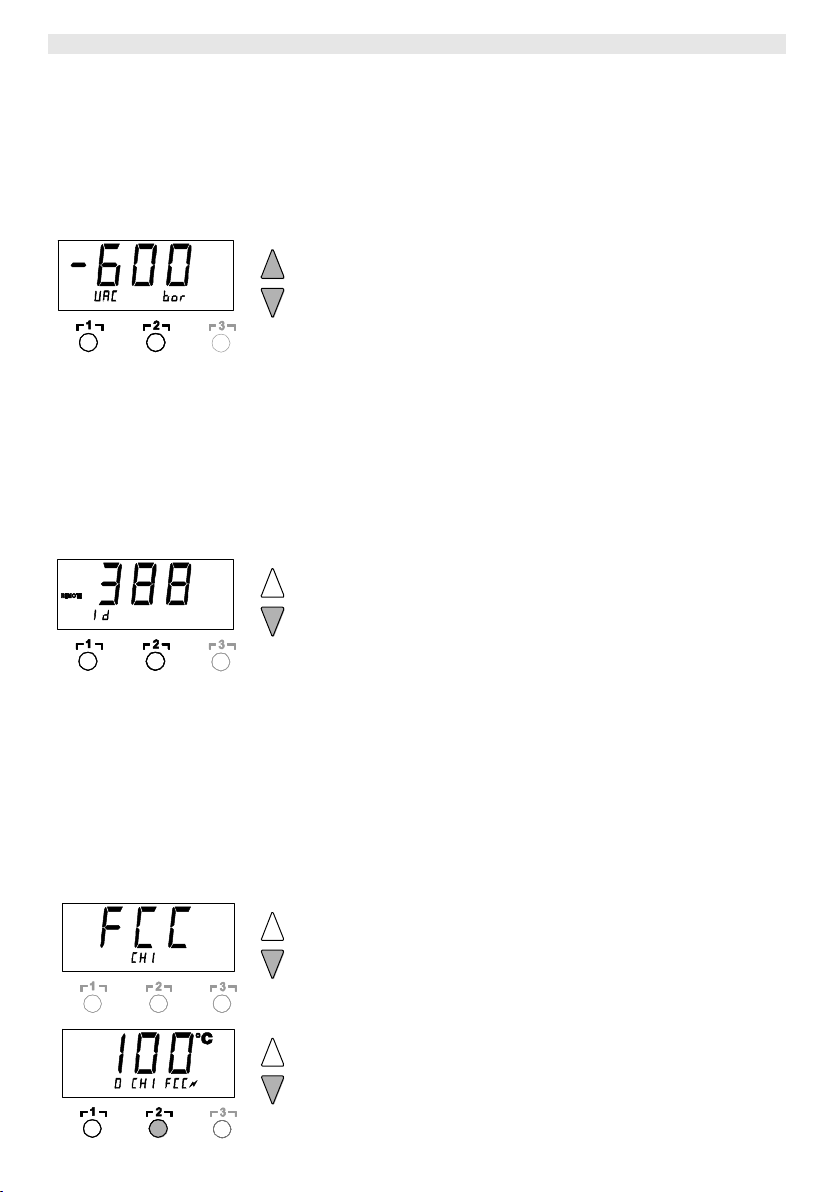
Defining the pressure-gauge threshold
This function can be used to define the maintenance interval of
the unsoldering tool. Here the value in mbar at which the electric
pressure gauge issues a warning signal when the intake system is
contaminated (LED (3) of the vacuum pump switches from green
to red) is defined. The set value is dependent on the suction
nozzles used.
Factory setting: -600 mbar
Settable: -400 mbar to -800 mbar
1. System (tips and filter) must be free
2. Select the menu item LEVEL in Menu 2.
3. Set the LEVEL pressure value with the UP or DOWN button.
The LED control check switches back and forth between red and
green. Use the UP button to increase vacuum by 50 to 80 mbar,
pinch the vacuum tube and check whether the control lamp
switches from green to red.
4. Proceed to the next menu item with the button ┌ 1 ┐ (back) or
┌ 2 ┐ (forward).
Setting the station identification (ID code)
When the optional USB port is used, several WR 3ME repair stations
can be activated and remote-controlled to their full operational
extent. To this end, each station requires a station identification
(ID code) so that it can clearly identified.
1. Select the menu item REMOTE ID in Menu 2.
2. Enter an ID with the UP or DOWN button
(possible values 0 – 999).
3. Proceed to the next menu item with the button ┌ 1 ┐ (back) or
┌ 2 ┐ (forward).
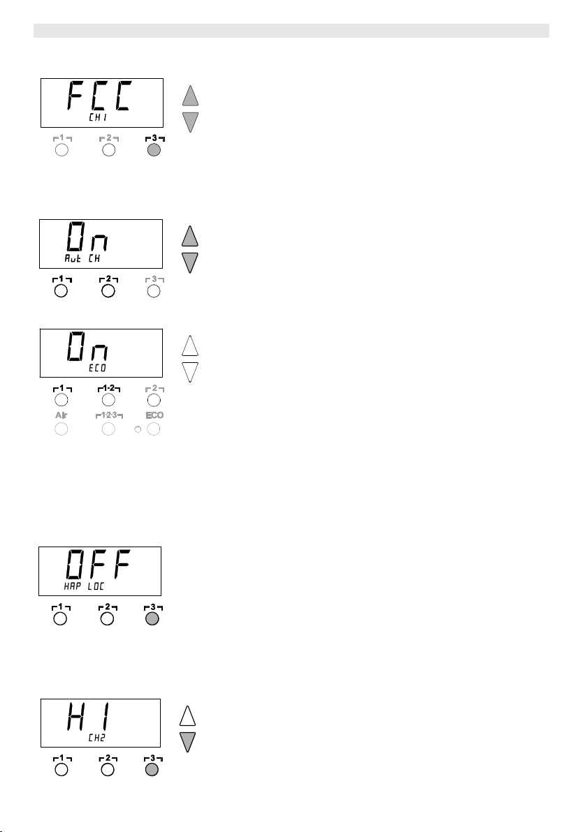
Executing the calibration function (Factory Calibration Check)
With the FCC function you can check the temperature precision of
the repair station and even out possible deviations. For this purpose,
the soldering-tip temperature must be measured with an external
temperature meter and a temperature measuring tip assigned to the
soldering tool. The corresponding channel must be selected prior to
calibration.
Changing calibration at 100 °C / 212 °F
1. Insert the temperature sensor (0.5 mm) of the external
temperature meter into the temperature measuring tip.
2. Select the menu item FCC in Menu 2.
3. Press the DOWN button.
Calibration point 100 °C / 212 °F is selected.
The soldering tip is now heated to 100 °C / 212 °F.
The control indicator flashes as soon as the temperature is
constant.
4. Compare the temperatures indicated by the meter with the
indications in the display.
5. Use the UP or DOWN button to set the difference between the
value indicated on the external meter and the value indicated on

WR 3ME 17-22
EN
EN
FR
IT
ES
PT
NL
SV
DK
FI
GR
TR
CZ
PL
HU
SK
SL
EE
LV
LT
Note
Press button ┌ 3 ┐ to exit the menu item without changes (EXIT).
Note
Press button ┌ 3 ┐ to exit the menu item without changes (EXIT).
the repair station.
Maximum possible temperature adjustment ± 40 °C (± 72 °F).
Example:
Display 100 °C, external measuring instrument 98 °C:
setting 2
Display 100 °C, external measuring instrument 102 °C:
setting 2
6. Press button ┌ 2 ┐ (Set) to confirm the value.
The temperature deviation is now reset to 0. Calibration at
100 °C / 212 °F is now concluded.
7. Exit menu 2 with button ┌ 3 ┐.
Changing calibration at 450 °C / 842 °F
1. Insert the temperature sensor (0.5 mm) of the external
temperature meter into the temperature measuring tip.
2. Select the menu item FCC in Menu 2.
3. Press the UP button.
Calibration point 450 °C / 842 °F is selected.
The soldering tip is now heated to 450 °C / 842 °F.
The control indicator flashes as soon as the temperature is
constant.
4. Compare the temperatures indicated by the meter with the
indications in the display.
5. Use the UP or DOWN button to set the difference between the
value indicated on the external meter and the value indicated on
the repair station.
Maximum possible temperature adjustment ± 40 °C (± 72 °F).
Example:
Display 450 °C, external measuring instrument 448 °C:
setting 2
Display 450 °C, external measuring instrument 452 °C:
setting 2
6. Press button ┌ 2 ┐ (Set) to confirm the value.
The temperature deviation is now reset to 0. Calibration at
450 °C / 842 °F is now concluded.
7. Exit Menu 2 with button ┌ 3 ┐.
18-22 WR 3ME
DE
EN
FR
IT
ES
PT
NL
SV
DK
FI
GR
TR
CZ
PL
HU
SK
SL
EE
LV
LT
Note
To protect itself, the pump switches off automatically after
20 minutes of continuous operation.
Resetting calibration to factory settings
1. Select the menu item FCC in Menu 2.
2. Press and hold down button ┌ 3 ┐.
3. Then press the UP and DOWN buttons simultaneously.
"FSE“ (Factory Setting Enabled) appears in the display.
The repair station is now reset to the factory calibration.
4. Proceed to the next menu item with the button ┌ 1 ┐ (back) or
┌ 2 ┐ (forward).
Deactivating / activating automatic channel change
This function can be used to deactivate the automatic channel
change, which was activated in the factory:
1. Select the menu item AUTO CHANNEL in menu 2.
2. Set the temperature unit with the UP or DOWN button.
(ON = activate / OFF = deactivate)
3. Proceed to the next menu item with the button ┌ 1 ┐ (back) or
┌ 2 ┐ (forward).
Activating / deactivating the ECO button (8)
The ECO button (activated at the factory) can be deactivated using
the ECO function:
1. Select the menu item ECO in Menu 2.
2. Set the status with the UP or DOWN button
(ON = activate / OFF = deactivate).
3. Change to the next menu option using the ┌ 1 ┐ (back) or ┌1·2┐
(forwards) button.
After activating the ECO button (8), it can be used to set all 2
channels to Standby mode. The green LED (9) lights up and the
channels are set to the set standby temperature.
If a switching holder is in use, the function is reset when the tool is
removed from the holder.
Activating / deactivating button lock HAP
This function can be used to change the button behaviour of the
HAP iron set in the factory. If the lock is activated, the HAP is
switched on the first time the button is pressed and switched off with
a further actuation.
1. Select the menu item HAP LOCK in Menu 2.
2. Set the temperature unit with the UP or DOWN button.
(ON = activate / OFF = deactivate)
3. Proceed to the next menu item with the button┌ 1 ┐ (back) or
┌ 2 ┐ (forward).
Setting the control characteristics for the WP 120
The HI / LO CONTROL function can be used to set the control
characteristic of the WP 120, which was set to HI in the factory:
1. Select the menu item HI / LO in Menu 2.
2. Set the status by pressing the UP (HI) or DOWN (LO) button.
WR 3ME 19-22
EN
EN
FR
IT
ES
PT
NL
SV
DK
FI
GR
TR
CZ
PL
HU
SK
SL
EE
LV
LT
WARNING!
Vacuum pump will be destroyed if operated without
the filter.
Check before starting soldering whether a main filter is
inserted.
8 Resetting to factory settings
Resetting the special functions
This function is described under "7.1 Selection special functions
menu 1", "Resetting the special functions to the factory settings“ on
page 10.
Resetting calibration to factory settings
This function is described under "7.2 Selecting special functions
menu 2", "Resetting calibration to factory settings" on page 15.
9 Care and maintenance of the WR 3ME
9.1 Servicing the filter
Regularly check the main filter for “VACUUM” and “AIR” and replace
if necessary.
Replacing the filter
1. Turn the cover cap for "Vac“ (13) or "Air“ (14) 45°
counterclockwise and remove.
2. Pull out the contaminated filter and dispose of properly.
3. Insert an original WELLER filter cartridge.
Make sure that the cover seal is correctly seated.
4. Insert pressure spring.
5. Refit the cover cap under slight pressure and turn 45° clockwise.
20-22 WR 3ME
DE
EN
FR
IT
ES
PT
NL
SV
DK
FI
GR
TR
CZ
PL
HU
SK
SL
EE
LV
LT
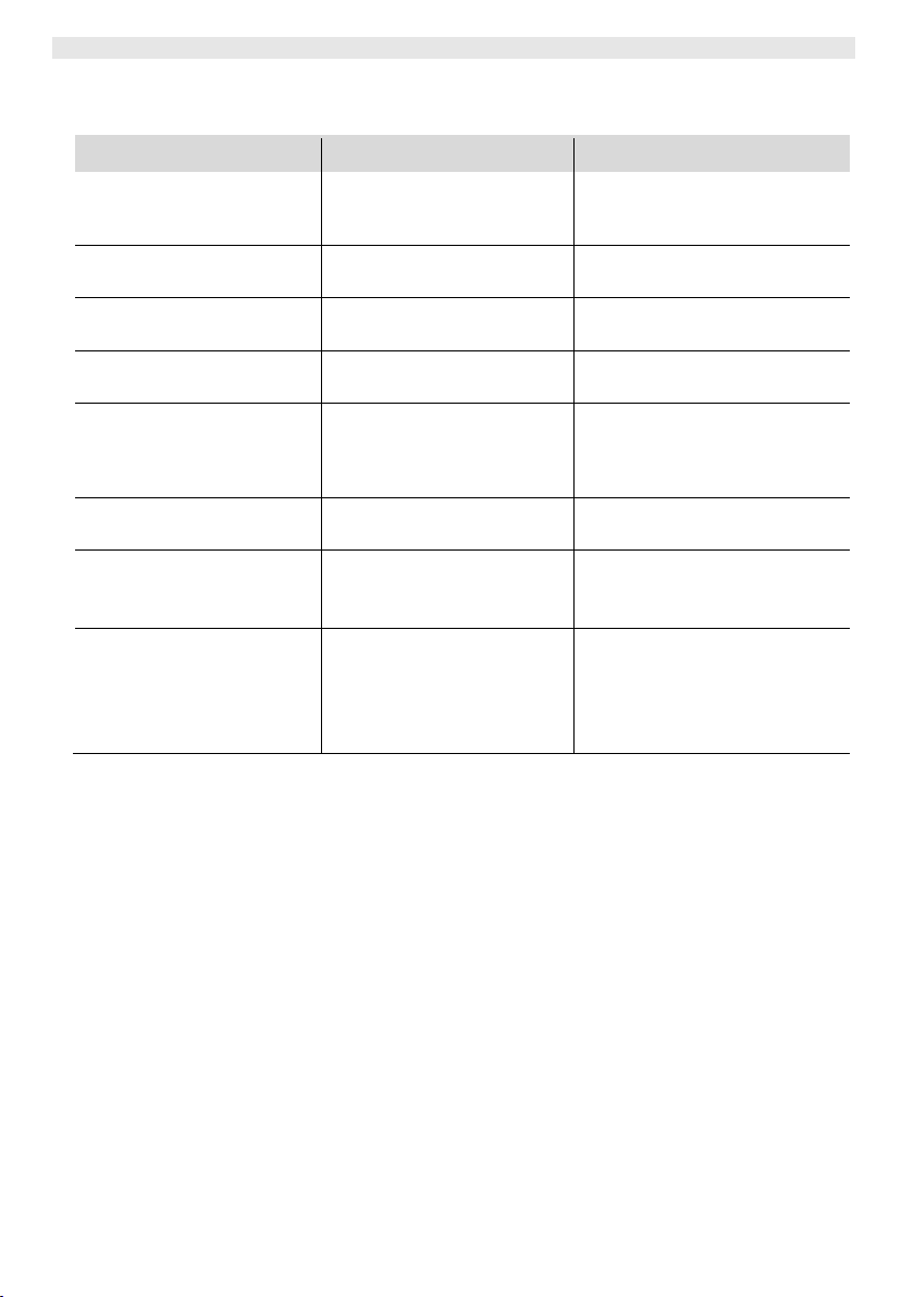
Message/Symptom
Possible cause
Corrective measures
Display: "- - -“
Tool has not been detected
Tool defective
Check connection of tool to
device
Check connected tool
HAP 200 is not working
HAP 200 not connected to
channel 1
Connect HAP 200 to channel 1
Display: "tip"
Soldering tip of microtool not
correctly inserted or defective
Insert soldering tip again
Replacing defective soldering tip
No air at HAP
Air hose not or incorrectly
connected
Connect air hose to AIR nipple
No vacuum at unsoldering tool
Vacuum hose not or
incorrectly connected
Unsoldering nozzle clogged
Connect vacuum hose to Vac
nipple
Maintain unsoldering nozzle with
cleaning tool
Status indication of VAC LEDs
incorrect
Pressure-gauge level not
correctly set
Set pressure-gauge level in special
menu 2
No display function (display off)
No mains supply voltage
Turn on mains power switch
Check mains supply voltage
Check device fuse
VAC LED red
Vacuum system clogged
Clean suction nozzle
Check filter; replace if yellow
Clean unsoldering tool – replace
filter
Check vacuum hose
10 Fault messages and fault elimination
 Loading...