

Page 1

WHA900
Operating Instructions
Page 2

Table of Contents Page
WHA900 Detail View 1
Technical Data 1
1. Cautions! / Warnings! 2
2. Description 2
3. Placing Into Operation 2
4. Operating Guidelines 3
5. Accessories 3
6. Packing List 3
7. Nozzles 4,5,6
Page 3
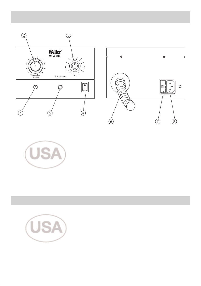
WHA900 Detailed View
1. LED Heater Control
2. VariableTemperature Control; Range 100°F and 1000°F
3. Air Flow Control; Range 5 to 50 l/minute
4. Power Switch
5. Start / Stop Push Button
6. Hot Air Pencil and Hose Assembly
7. Fuse T 10 Amp
8. Receptacle 120 VAC
Technical Data:
Dimensions: 8 3/16” L; 6 5/8” W; 4 1/4” H
Main Voltage: 120 VAC
Power consumption: 750 WATTS
Hot Air Pencil output: 700 WATTS
Fuse: T 10 AMP
Temperature Control: Variable between 100°F and 1000°F
Temperature Control accuracy: ± 54°F
Flow Control: Variable between 5 - 50 l/min
Noise Level: 56dB(A) distance 1m at max. airflow level
1
Page 4

nglish
E
Thank you for placing your trust in our company
by purchasing the Weller WHA900 Hot Air Station.
This product meets or exceeds the requirements
established by Weller for superior performance,
versatility and quality.
1. Cautions! / Warnings!
Please read these Operating Instructions and the
attached Safety Information carefully prior to initial
operation. Failure to observe the safety warnings
may result in accident, injury, or risk to health.
The manufacturer shall not be liable for damage
resulting from misuse of the machine or unauthorized alterations.
Warning: This product when used for soldering
and similar applications, produces chemicals
known to the State of California to cause cancer
and birth defects or other reproductive harm.
Safety Information:
● Always place the soldering iron in its original
holder
● Remove all inflammable objects from the proximity of the hot soldering tool.
● Use suitable protective clothing to prevent the
risk of burns associated with molten solder.
● Never leave a hot soldering iron unattended.
● Never work on electrically live circuits or com-
ponents.
● Always wear eye protection when working with
soldering and desoldering applications.
The Weller WHA900 Hot Air Station corresponds
to the EC Declaration of Conformity in accordance
with the basic safety requirements of Directives
89/336/EEC and 73/23EEC.
2. Description
The WHA900 hot air station was developed for
general soldering re-work on Surface Mount components. The temperature of the hot air is controlled electronically and is variable between
100°F and 1000°F. 120 VAC (8) is required to
operate the unit. The air flow is variable electronically within the range of approximately 5-50
l/minute and is generated by a self contained
pump. The hot air is activated using the Start/Stop
Push Button, (5) at the front of the unit.
2
The WHA900 is grounded through the 120 VAC
three wire power cord.
Standby mode:
This unit has a power-on function to activate a
Standby Mode (or secondary temperature airflow
setting). Before switching on the unit, choose the
Temperature and the Airflow settings that you
would prefer to use for the Standby Mode of operation.
Activating Standby:
Adjust the Temperature and Airflow control to the
desired Standby setting. Depress the Start/Stop
push button and hold while switching on the unit.
Keep the button depressed for approximately 5
seconds after turning the unit on. The pump will
start and the Standby function is activated. When
the unit is switched on, the Temperature and the
Airflow will be set to the Standby values. When
you depress the Start/Stop push button, the
Airflow and Temperature will go to the actual “Set”
values. The actual “Set” values should be set at a
normal Temperature and Airflow settings capable
of performing the rework application. Depress the
button again and the unit will go back to the
Standby values.
Note: To change the Standby settings, you must
first Deactivate Standby Mode as described
below.
Deactivating Standby:
If the Standby function is activated, depress the
Start/Stop push button while switching on the unit.
Keep the button depressed for about 5 seconds.
The unit is now in the original operating mode.
Repeat the “Activating Standby” directions to
assign new preferred settings.
3. Placing Into Operation
Note: Safety rest must be formed before tool use.
Place the hot air pencil in the formed safety rest
with the nozzle in a raised position to prevent
damage to w
ply voltage is consistent with the information on
the station label. Before connecting to the 120
VAC po
(2) and the air flow on (3) and switch on the unit
at the power switch (4). The LED will flash slowly
to indicate the unit has reached the Set
Temperature.
ork bench. Check to be sure the sup-
er source
w
, set the desired temper
ature
Page 5

nglish
E
The Airflow and Temperature are activated after
depressing the Start/Stop Push Button. Heat-up
time of the nozzle depends primarily on the size
of the nozzle and the air flow.
Temperature Offset
1. With the WHA900 off and the heater cooled down. Place Measuring Nozzle ( 0058736875 ) on to the
end of the Hot Air Pencil and fasten it with the set screw.
2. Insert the 0.5mm Type “K” Thermocouple, ( 0058736786 ) into the hole of the Measuring Nozzle and
place the Hot Air Pencil in the safety rest. Switch the device on.
3. Choose the temperature you want to adjust with the temperature knob.
4. Activate the unit with the Start / Stop push button. Set the Airflow Knob to 4. Wait approximately 5
minutes before continuing.
5. Read the temperature value indicated on the measuring instrument.
6. If the temperature has to be corrected, depress and hold the Start / Stop push button for approximately 15 seconds while the hot air is activated. The green LED (1) will light continuosly.
7. While the green LED (1) is continuosly lit, immediately turn the temperature knob slightly beyond center and rotate back to the center position (550 °F). This will be your “zero” point for adjustments. Rotate
clockwise for positive and counterclockwise for negative adjustments.
8 Adjust the temperature knob until the desired setting is indicated on the measuring device and has
stabilized. Depress the Start / Stop push button to confirm.
9. The Temperature Offset function is now complete. You may adjust the temperature knob to your original setting.
10. Repeat steps 3-9 if additional Offset is required.
Warning: Do not direct the hot air pencil at
people or inflammable objects.
4. Operating guidelines
Changing the nozzles;
The hot air nozzles are fixed to the heating element with a set/attachment screw. Loosen the
set/attachment screw to remove nozzles.
5. Accessories
For Nozzle range see “ Hot Air Nozzles “.
0051504899 - Multiple Rest for six nozzles.
0051504999 - Nozzle Exchange Tool
2.5 mm Hex Wrench
6. Packing List
WHA900 Control Unit
Power Cord
Safety Rest
( 1 ) Set / Attachment Screw
Operating Instructions
Safety Information
Subject to technical change without notice!
3
Page 6

ot Air Nozzles
H
Ø
1,7 x 45° mm
Ø
.067 x 45° in
0058736882
Ø 2.5 mm
Ø .098 in
0058736881
Ø 4 mm
Ø .157 in
0058736867
Ø 7 mm
Ø .280 in
0058736870
Made to
Order
4
RD11
Ø 2,5 x 9,5 mm
Ø .098 x .374 in
0058736883
Ø 11.5 mm
Ø .453 in
0058736836
Page 7

14,8 x 14,8 mm
.583 x .583 in
0058736818
11 x 11 mm
.433 x .433 in
0058736839
21,5 x 14.8 mm
.846 x .583 in
0058736840
19 x 12 mm
.748 x .472 in
0058736841
ot Air Nozzles
H
14 x 10 mm
.551 x .394 in
0058736842
10 x 8 mm
.394 x .315 in
0058736843
Measuring
Nozzle
0058736875
Adapter
0058750722
5
Page 8

ot Air Nozzles
H
31.3 x 31.3 mm
1.23 x 1.23 in
0058736833
26 x 26 mm
1.024 x 1.024 in
0058736804
20.5 x 20.5 mm
.807 x .807 in
0058736807
17.5 x 23.5 mm
.689 x .925 in
0058750721
18 x 18 mm
.709 x .709 in
0058736814
15.5 x 13 mm
.610 x .512 in
0058736837
14 x 10 mm
.551 x .394 in
0058736838
6
Page 9

Made To Order Nozzles ( Contact for Quote )
ot Air Nozzles
H
24 x 12 mm
.945 x .472 in
0058736880
43 x 43 mm
1.693 x 1.693 in
0058736890
36 x 36 mm
1.417 x 1.417 in
0058736891
27 x 14 mm
1.063 x .551 in
0058736892
29 x 17 mm
1.142 x .669 in
0058736877
35.5 x 23 mm
1.398 x .906 in
0058736998
48.5 x 30.5 mm
1.909 x 1.201 in
0058736999
44 x 32 mm
1.732 x 1.260 in
0058736858
48.5 x 38 mm
1.909 x 1.496 in
0058750709
61 x 38 mm
2.402 x 1.496 in
0058750714
7
Page 10

ot Air Nozzles
H
Made To Order Nozzles ( Contact for Quote )
12 x 27 mm
.472 x 1.063 in
0058736880
38 x 38 mm
1.496 x 1.496 in
0058736890
40 x 40 mm
1.575 x 1.575 in
0058736891
8
Page 11

wwwwww..ccooooppeerrhhaannddttoooollss..ccoom
m
UU..SS MMaaiilliinngg AAddddrreessss:
CCooooppeerr HHaanndd TToooolls
P.O. Box 728
Apex, NC 27502-0728
UU..SS SShhiippppiinngg AAddddrreessss:
1000 Lufkin Road
Apex, N.C. 27539
Tel: (919) 387-0099
Fax: (919) 387-2379
For inquiries concerning Technical /
Customer Service please call:
(800) 476-3030 Ext. 1
CCaannaaddaa SShhiippppiinngg AAddddrreessss:
CCooooppeerr TToooolls
164 Innisfil Street
Barrie, Ontario
Canada L4N 3B7
Attn: Repairs
Fax: 1-800-403-TOOL (8665)
Phone: 705-728-5564 Ext. 2026
:
s
:
:
s
Weller is a registered Trademark and registered Design of Cooper Industries, Inc.
005 XX XXX XX / 03.06 © 2006 Cooper Industries
 Loading...