

Weller WDH 10T, WDH 20T Operating Instructions Manual
WDH 10T/20T
Betriebsanleitung - Operating Instructions - Mode d'emploi - Istruzioni per l'uso - Manual de uso Manual do utilizador - Gebruiksaanwijzing - Instruktionsbok - Betjeningsvejledning - Käyttöohjeet Οδηγίες Λειτουργίας- Kullanım kılavuzu - Návod k použití - Instrukcja obsługi - Üzemeltetési utasítás Návod na používanie - Navodila za uporabo - Kasutusjuhend - Lietosanas instrukcija -
Naudojimo instrukcija
005 57 098 00
Replaces: First Edition


WDH 10T/20T – Operating Instructions I
Deutsch
DE
English
Français
EN
FR
Italiano
IT
Español
ES
Português
Nederlands
Svenska
Dansk
PT
NL
SV
DK
Suomi
Eλληvık
FI
GR
Türkçe
TR
The data specified above only serve to
describe the product. No statements
concerning a certain condition or suitability for
a certain application can be derived from our
information. The given information does not
release the user from the obligation of own
judgement and verification. It must be
remembered that our products are subject to a
natural process of wear and aging.
© This document, as well as the data,
specifications and other informations set forth
in it, are the exclusive property of Cooper
Tools GmbH. Without their consent it may not
be reproduced or given to third parties.
Subject to modifications.
Printed in Germany.
03.2007
Česky
Polski
Magyar
Slovensky
Slovenščina
Saksa keel
Lietuviškal
Vāciski
CZ
PL
HU
SK
SL
EE
LV
LT

WR 3M II

WDH 10T/20T
Betriebsanleitung
EN FR IT ES PT NL SV DK FI GR TR CZ PL HU SK SL EE LV LT DE
WDH 10T/20T
WDH 10T/20T
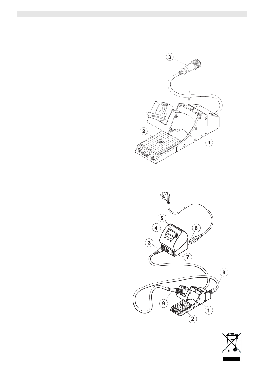
Geräteübersicht
1 Schaltablage Gehäuse
2 Reinigungseinsatz Standard
3 Anschluss Schaltablage
4 Down-Taste
5 Up-Taste
6 Netzanschluss
7 Netzschalter
8 Anschluss Lötkolben
9 Lötkolben

WDH 10T/20T 3-8
Inhalt
1
Zu dieser Anleitung.................................................................. 3
2 Zu Ihrer Sicherheit ................................................................... 3
3 Lieferumfang............................................................................4
4 Gerätebeschreibung ................................................................ 4
5 Schaltablage in Betrieb nehmen ..............................................5
6 Gerät bedienen........................................................................ 6
7 WDH 10T/20T pflegen und warten........................................... 7
8 Fehlermeldungen und Fehlerbehebung.................................... 7
9 Zubehör ................................................................................... 7
10 Entsorgung.............................................................................. 7
11 Garantie................................................................................... 8
1 Zu dieser Anleitung
Wir danken Ihnen für das mit dem Kauf der Weller WDH 10T/20T
erwiesene Vertrauen. Bei der Fertigung wurden strengste
Qualitätsanforderungen zugrunde gelegt, die eine einwandfreie
Funktion des Gerätes sicherstellen.
Diese Anleitung enthält wichtige Informationen, um die Schaltablage
WDH 10T/20T sicher und sachgerecht in Betrieb zu nehmen, zu
bedienen, zu warten und einfache Störungen selbst zu beseitigen.
Z Lesen Sie diese Anleitung vor Inbetriebnahme des Gerätes
vollständig, bevor Sie mit der Schaltablage WDH 10T/20T
arbeiten.
Z Bewahren Sie diese Anleitung so auf, dass sie für alle Benutzer
zugänglich ist.
DE EN FR IT ES PT NL SV DK FI GR TR CZ PL HU SK SL EE LV LT
1.1 Berücksichtigte Richtlinien
Die Weller Schaltablage WDH 10T/20T entspricht den Angaben der
EG Konformitätserklärung mit den Richtlinien 89/336/EWG und
73/23 EWG.
1.2 Mitgeltende Dokumente
− Betriebsanleitung Ihres Steuergerätes mit Begleitheft
Sicherheitshinweise
− Betriebsanleitung Ihres Lötwerkzeugs
2 Zu Ihrer Sicherheit
Die Schaltablage WDH 10T/20T wurde entsprechend dem heutigen
Stand der Technik und den anerkannten sicherheitstechnischen
4-8 WDH 10T/20T
Regeln hergestellt. Trotzdem besteht die Gefahr von Personen- und
Sachschäden, wenn Sie die Sicherheitshinweise im beiliegenden
Sicherheitsheft des Steuergeräts sowie die Warnhinweise in dieser
Anleitung nicht beachten. Geben Sie die Schaltablage an Dritte stets
zusammen mit der Betriebsanleitung weiter.
2.1 Bestimmungsgemäßer Gebrauch
Verwenden Sie die Schaltablage WDH 10T/20T ausschließlich
gemäß dem in der Betriebsanleitung angegebenen Zweck zum
Ablegen der unten aufgeführten Lötwerkzeuge unter den hier
angegebenen Bedingungen. Der bestimmungsgemäße Gebrauch
der Schaltablage WDH 10T/20T schließt auch ein, dass
− Sie diese Anleitung beachten,
− Sie alle weiteren Begleitunterlagen beachten,
− Sie die nationalen Unfallverhütungsvorschriften am Einsatzort
beachten.
Für eigenmächtig vorgenommene Veränderungen am Gerät wird
vom Hersteller keine Haftung übernommen.
3 Lieferumfang
WDH 10T
− Schaltablage WDH 10T
− Betriebsanleitung WDH 10T
WDH 20T
− Schaltablage WDH 20T
− Betriebsanleitung WDH 20T
WSP 80IG Set
− Schaltablage WDH 10T
− Lötkolben WSP 80IG
− Betriebsanleitung WDH 10T
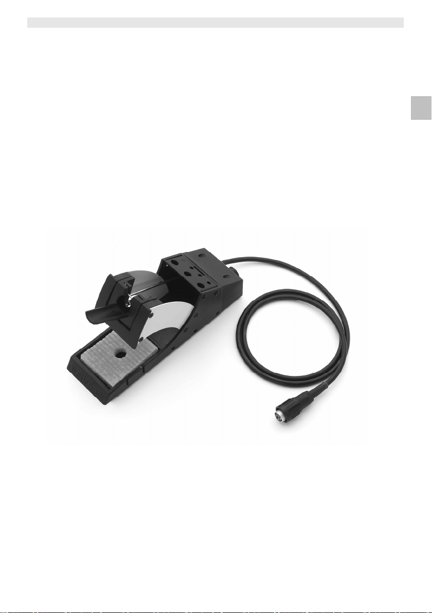
4 Gerätebeschreibung
Die Weller WDH 10T/20T Schaltablage bietet, im Gegensatz zur
normalen Sicherheitsablage, eine von der Lötstation auswertbare
Schaltfunktion. In der Schaltablage ist ein Mikroschalter integriert,
der beim Ablegen und Herausnehmen des Lötkwerkzeugs betätigt
wird.
Beim Einstecken der Schaltablage in eine digitale Weller Lötstation
findet eine automatische Erkennung statt und erweitert, je nach
Anwendung, den standardmäßigen Funktionsumfang für die
Temperaturabsenkung oder Ventilsteuerung (nur WAD 101).
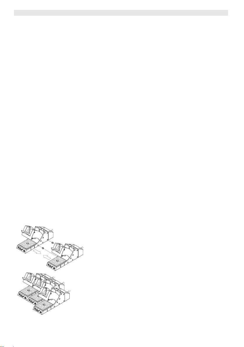
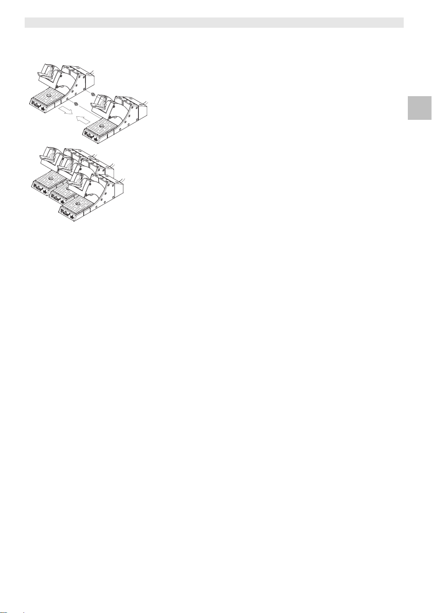
Zur Befestigung können mehrere Schaltablagen seitlich
zusammengesteckt werden.
WDH 10T/20T 5-8
WARNUNG!
4.1 Technische Daten WDH 10T/20T
Abmessungen L x B x H (mm): 208 x 65 x 115
Gewicht 0,69 kg
Passende Lötwerkzeuge
Anschließbare
Steuergeräte
L x B x H (inch): 81,89 x 2,56 x 4,53
− WDH 10T: WSP 80, WSP 81,
WP 80, WSP 80IG
− WDH 20T: WMP
WSD 81, WSD 161, WSD 151,
WSD 151R, WDD 81V, WSL, WSL 2,
WAD 101, WMRS, WMD 1S,
WMD 3, WD 1, WD 2, WD 1M,
WD 2M, WR 3M
5 Schaltablage in Betrieb nehmen
Verbrennungsgefahr beim Arbeiten mit
Lötwerkzeugen und Erstickungsgefahr bei Arbeiten
mit inerten Gasen.
Beim Löten besteht Verbrennungsgefahr bei Berührung des
heißen Lötwerkzeugs. Beim Arbeiten mit Inertgasen, z. B. mit
dem WSP 80IG, besteht Erstickungsgefahr.
Z Den Lötkolben stets in der Schaltablage ablegen.
Z Bei Verwendung von inerten Gasen ist für eine ausreichende
Raumbelüftung zu sorgen!
Z Bei längerem Nichtgebrauch den Druckanschluss (2) des
Gerätes drucklos schalten.
1. Die Schaltablage sorgfältig auspacken.
2. Sicherstellen, dass die anzuschließende Lötstation ausgeschaltet
ist.
3. Den 7-poligen Stecker (3) des Verbindungskabels an der
Lötstation einstecken und verriegeln.
4. Den Lötkolben (9) in der Schaltablage (1) ablegen in die 7-polige
Buchse (8) einstecken und verriegeln.
5. Lötstation einschalten (7).
Zum Betrieb der Schaltablage mit dem Inert-Gas-Lötkolben
WSP80IG wird das Steuergerät WAD 101 benötigt. Beachten Sie
hierzu die Betriebsanleitung Ihres Steuergeräts.
DE EN FR IT ES PT NL SV DK FI GR TR CZ PL HU SK SL EE LV LT
6-8 WDH 10T/20T
6 Gerät bedienen
6.1 Temperaturabsenkung (SETBACK) und
Automatische Abschaltzeit (AUTO-OFF) mit
angeschlossener Schaltablage
Am Steuergerät können SETBACK-Zeit und AUTO-OFF-Zeit
eingestellt werden (WD1-, WD2-, WD1 M-, WD2 M- und WR 3MGeräte) oder sind fest vorgegeben (WSD- und WMD-Geräte).
Nach Ablegen des Lötwerkzeugs in der Schaltablage erfolgt die
Temperaturabsenkung und/oder Abschaltung (AUTO-OFF) je nach
Einstellung am Steuergerät. Das jeweilige Schaltverhalten ist in der
folgenden Tabelle dargestellt.
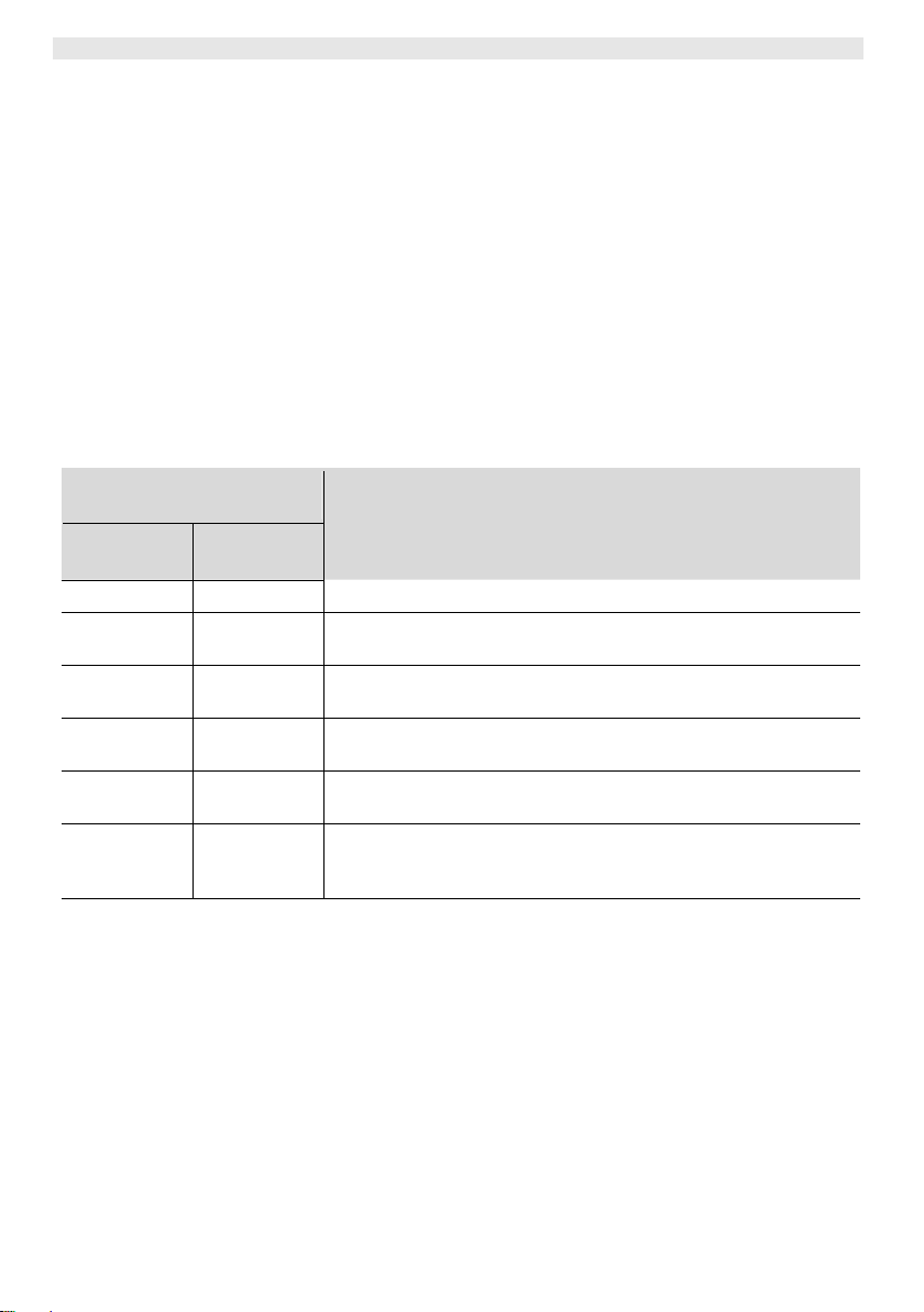
Tab. 1. Temperatur- und Abschaltverhalten der Steuergeräte WD1, WD2, WD1 M, WD2 M, WR 3M,
WSD und WMD bei unterschiedlicher Einstellung der SETBACK- und AUTO-OFF-Funktionen
Mögliche Einstellungen am
Steuergerät1)
SETBACK
Time [1-99 min]
OFF Time
[1-999 min]
0 0 Lötwerkzeug wird in der Ablage2) abgeschaltet.
ON 0
0 Time
ON Time
Time 0
Time Time
1)
Bei WSD- und WMD-Geräten sind nur die Einstellungen 0/0 und ON/TIME möglich, wobei die
jeweiligen Zeitwerte für SETBACK (20 Minuten) und AUTO-OFF (60 Minuten) fest vorgegeben sind.
Abweichende SETBACK-Zeiten sind bei diesen Gerätetypen nur mit dem externen Eingabegerät
WCB2 möglich.
2)
Außerhalb der Schaltablage bleibt das Lötwerkzeug immer auf der eingestellten Solltemperatur.
Die Ablagefunktion wird nach dem ersten Ablegen des Lötwerkzeugs aktiviert
3)
Die STANDBY-Temperatur muss unter der eingestellten Solltemperatur liegen, sonst ist die
SETBACK-Funktion inaktiv.
Hinweis
Temperaturschaltverhalten nach Ablegen des Lötwerkzeugs
in der Schaltablage
2)
Lötwerkzeug wird in der Ablage
auf die STANDBY-Temperatur3)
heruntergeregelt.
2)
Lötwerkzeug wird in der Ablage
nach Ablauf der OFF-Zeit
abgeschaltet.
2)
Lötwerkzeug wird in der Ablage
auf die STANDBY-Temperatur3)
heruntergeregelt und wird nach Ablauf der OFF-Zeit abgeschaltet.
2)
Lötwerkzeug wird in der Ablage
STANDBY-Temperatur
3)
heruntergeregelt.
Lötwerkzeug wird in der Ablage
auf die STANDBY-Temperatur
nach der SETBACK-Zeit auf die
2)
nach Ablauf der SETBACK-Zeit
3)
heruntergeregelt, und nach Ablauf
der OFF-Zeit abgeschaltet.
Beachten Sie zur Einstellung und Ein-/Ausschaltung der
SETBACK- und AUTO-OFF-Funktionen die Betriebsanleitung Ihres
Steuergeräts.

WDH 10T/20T 7-8
6.2 Ventilsteuerung mit Schaltablage
ein-/ ausschalten (WAD 101)
Beim Betrieb eines Lötkolbens mit inertem Gas und der Verwendung
der Schaltablage muss die Ventilsteuerung am Steuergerät
WAD 101 eingestellt werden. Hierbei sind zwei Schaltzustände
möglich:
− A-1: die Ventilsteuerung ist eingeschaltet. Das Ventil wird durch
die Schaltablage mit der Funktion EIN/AUS angesteuert. In
diesem Betriebszustand steht die SETBACK-Funktion „OFF“ nicht
zur Verfügung.
− A-0: die Ventilsteuerung ist ausgeschaltet. Die SETBACK-
Funktion ist uneingeschränkt verfügbar.
Hinweis
Beachten Sie zur Einstellung der Ventilsteuerungsfunktion die
Betriebsanleitung Ihres Steuergeräts.
7 WDH 10T/20T pflegen und warten
Der Schwamm des Reinigungseinsatzes sollte regelmäßig gereinigt
und von Lotresten befreit werden.
8 Fehlermeldungen und Fehlerbehebung
Meldung/Symptom Mögliche Ursache Maßnahmen zur Abhilfe
Lötkolben schaltet nach dem
Ablegen nicht ab
SETBACK Time an der
Lötstation ist aktiviert
Lötkolben schaltet erst nach der
eingestellten Zeit ab:
Z SETBACK Time an der
Lötstation auf 0 setzen.
DE EN FR IT ES PT NL SV DK FI GR TR CZ PL HU SK SL EE LV LT
Lötkolben schaltet nach dem
Herausnehmen nicht mehr ein
Ablage ist nicht richtig
angeschlossen
Beweglicher Trichter oder
Schaltgestänge klemmt
Z Anschlusskabel überprüen
- Ablagekabel – Lötstation
- Lötkolben - Ablage
Trichter und Schaltgestänge
überprüfen
9 Zubehör
Trockenreinigungseinsatz WDC 2, 005 15 125 99
Spiralwolle, 005 13 825 99
10 Entsorgung
Entsorgen Sie ausgetauschte Geräteteile und alte Geräte gemäß
den Vorschriften Ihres Landes.

8-8 WDH 10T/20T
11 Garantie
Die Mängelansprüche des Käufers verjähren in einem Jahr ab
Ablieferung an ihn. Dies gilt nicht für Rückgriffsansprüche des
Käufers nach §§ 478, 479 BGB.
Aus einer von uns abgegebenen Garantie haften wir nur, wenn die
Beschaffenheits- oder Haltbarkeitsgarantie von uns schriftlich und
unter Verwendung des Begriffs „Garantie“ abgegeben worden ist.

WDH 10T/20T
Operating Instructions
EN FR IT ES PT NL SV DK FI GR TR CZ PL HU SK SL EE LV LT DE

WDH 10T/20T
WDH 10T/20T
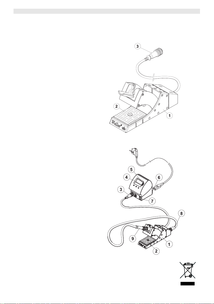
Equipment overview
1 Housing switching holder
2 Standard cleaning insert
3 Switching holder connection
4 Down button
5 Up button
6 Mains connection
7 Mains switch
8 Soldering iron connection
9 Soldering iron

WDH 10T/20T 3-8
Contents
1
About these instructions........................................................... 3
2 For your safety......................................................................... 3
3 Scope of supply ....................................................................... 4
4 Device description....................................................................4
5 Initial operation of the switching holder.....................................5
6 Operating the device................................................................ 6
7 WDH 10T/20T: maintenance and care ..................................... 7
8 Fault messages and fault elimination ....................................... 7
9 Accessories............................................................................. 7
10 Disposal................................................................................... 7
11 Warranty.................................................................................. 8
1 About these instructions
Thank you for placing your trust in our company by purchasing the
Weller WDH 10T/20T. Production was based on stringent quality
requirements which guarantee the perfect operation of the device.
These instructions contain important information for safe and correct
initial operation of the switching holder WDH 10T/20T, including
continued operation, maintenance and self-correction of simple
faults.
Z Read these Operating Instructions completely prior to initial
operation of the device and before starting work with the
switching holder WDH 10T/20T.
Z Ensure that these instructions are accessible to all users.
DE EN FR IT ES PT NL SV DK FI GR TR CZ PL HU SK SL EE LV LT
1.1 Applied directives
The Weller switching holder WDH 10T/20T complies with the
specifications of the EC Declaration of Conformity based on
Directives 89/336/EEC and 73/23 EEC.
1.2 Further applicable documentation
− Operating Instructions of your control unit including the
accompany booklet on Safety Instructions
− Operating Instructions of your soldering tool
2 For your safety
The switching holder WDH 10T/20T has been manufactured in
accordance with state-of-the-art technology and the recognised
technical safety regulations. In spite of this, there is a risk of injury
and damage to property if the safety instructions in the enclosed
safety booklet and the warning notes in these Operating Instructions
4-8 WDH 10T/20T
are not observed. If the switching holder is passed on to third
parties, always hand over the Operating Instructions as well.
2.1 Specified use
Always use the switching holder WDH 10T/20T exclusively for the
purpose specified in these Operating Instructions: for depositing the
soldering tools listed below under the conditions specified in these
instructions. Specified use of the switching holder WDH 10T/20T
also includes
− observance of these Operating Instruction,
− observance of all other accompanying documentation,
− observance of the locally applicable accident prevention
regulations.
The manufacturer shall not be liable for damage resulting from
unauthorised alterations to the machine.
3 Scope of supply
WDH 10T
− Switching holder WDH 10T
− Operating Instructions WDH 10T
WDH 20T
− Switching holder WDH 20T
− Operating Instructions WDH 20T
WSP 80IG Set
− Switching holder WDH 10T
− Soldering iron WSP 80IG
− Operating Instructions WDH 10T
4 Device description
The Weller WDH 10T/20T switching holder, as opposed to a
standard safety rest, provides a switching function that can be
evaluated by the soldering station. A microswitch integrated in the
switching holder is actuated when the soldering tool is deposited or
removed.
When the switching holder is inserted in a digital Weller soldering
station, automatic detection takes place and, depending on the
application, the standard range of functions for temperature
decrease or valve control is extended (only WAD 101).
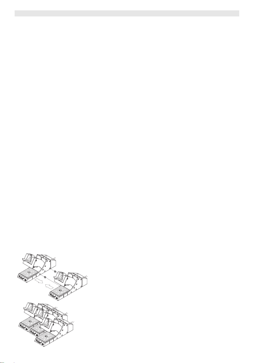
For securing purposes, several switching holders can be connected
together at the side.

WDH 10T/20T 5-8
WARNING!
4.1 Technical data WDH 10T/20T
Dimensions L x W x H (mm): 208 x 65 x 115
Weight 0.69 kg
Matching soldering tools
Connectable
control units
L x W x H (inches): 81.89 x 2.56 x
4.53
− WDH 10T: WSP 80, WSP 81,
WP 80, WSP 80IG
− WDH 20T: WMP
WSD 81, WSD 161, WSD 151,
WSD 151R, WDD 81V, WSL, WSL 2,
WAD 101, WMRS, WMD 1S,
WMD 3, WD 1, WD 2, WD1 M,
WD 2M, WR 3M
5 Initial operation of the switching holder
Risk of burns when working with soldering tools and
risk of suffocation when working with inert gases.
There is a risk burning if you touch the hot soldering tool. When
working with inert gases, e.g. with the WSP 80IG, there is a risk of
suffocation.
Z Always deposit the soldering iron in the switching holder.
Z When using inert gases, ensure that room ventilation is
adequate!
Z If not used for long period, depressurise the pressure
connection (2) of the device.
1. Carefully unpack the switching holder.
2. Ensure that the soldering station to be connected is switched off.
3. Insert the 7-pin connector (3) of the connecting cable at the
soldering station and lock it..
4. Deposit the soldering iron (9) in the switching holder (1) and
insert in the 7-pin pushing (8) and lock..
5. Switch on the soldering station (7).
To operate the switching holder with the inert gas soldering iron
WSP80 IG, control unit WAD 101 is required. Observe the Operating
Instructions of your control unit when doing this.
DE EN FR IT ES PT NL SV DK FI GR TR CZ PL HU SK SL EE LV LT

6-8 WDH 10T/20T
6 Operating the device
6.1 Temperature decrease (SETBACK) and
automatic switch-off time (AUTO-OFF) with
connected switching holder
The SETBACK time and AUTO-OFF time can be set at the control
unit (WD1, WD2, WD1 M, WD2 M- and WR 3M devices), or are
permanently specified (WSD and WMD devices).
After depositing the soldering tool in the switching holder, the
temperature decreases and/or the system shuts down, depending on
the setting at the control unit. The respective switching behaviour is
displayed in the following table.
Tab. 1. Temperature and switch-off behaviour of the control units WD1, WD2, WD1 M, WD2 M,
WR 3M, WSD and WMD with different settings of the SETBACK and AUTO-OFF functions
Possible settings at the control
unit1)
SETBACK time
[1-99 mins]
OFF time
[1-999 mins]
0 0 The soldering tool is switched off in the holder2).
ON 0
0 Time
ON Time
Time 0
Time Time
1)
With the WSD and WMD devices, only the settings 0/0 and ON/TIME are possible, whereby the
respective time values for SETBACK (20 minutes) and AUTO-OFF (60 minutes) are permanently
specified. With these device types, deviating SETBACK times are only possible with the external
input device WCB2.
2)
Outside the switching holder, the soldering tool always remains at the set specified temperature.
The holder function is activated after the first time the soldering tool is deposited.
3)
The STANDBY temperature must be below the set specified temperature; otherwise the SETBACK
function is inactive.
Temperature switching behaviour after depositing the soldering tool
in the switching holder
2)
The soldering tool is regulated in the holder
temperature
3)
.
The soldering tool is switched off in the holder
down to STANDBY
2)
after the OFF time
has elapsed.
2)
The soldering tool is regulated in the holder
STANDBY temperature
3)
and is switched off after the OFF time has
down to the
elapsed.
2)
The soldering tool is regulated in the holder
temperature
The soldering tool is regulated in the holder
STANDBY temperature
3)
after the SETBACK time has elapsed.
3)
after the SETBACK time has elapsed and
down to STANDBY
2)
down to the
is switched off after the OFF time has elapsed.
Note
Observe the Operating Instructions of your control unit when setting
and switching the SETBACK and AUTO-OFF functions on and off.

WDH 10T/20T 7-8
6.2 Switching valve control with switching holder
on/off (WAD 101)
When operating a soldering iron with inert gas and when using the
switching holder, the valve control must be set at the control unit
WAD 101. Two switching statuses are possible:
− A-1: the valve control is switched on. The valve is activated by the
switching holder with the ON/OFF function. In this operating
status, the SETBACK function "OFF" is not available.
− A-0: the valve control is switched off. The SETBACK function is
available without restrictions.
Note
Observe the Operating Instructions of your control unit when
setting the valve control function.
7 WDH 10T/20T: maintenance and care
The sponge of the cleaning insert should be cleaned regularly to
remove solder residue.
8 Fault messages and fault elimination
Message/Symptom Possible cause Corrective measures
Soldering iron does not switch
off after being deposited on
holder
Soldering iron no longer
switches on after removal from
holder
SETBACK time on the
soldering station is activated
The holder is not correctly
connected
Movable funnel or shift linkage
is jammed
Soldering iron only switches off
after the set time:
Z Set the SETBACK time on the
soldering station to 0.
Z Check connecting cable
- Holder cable – soldering
station
- Soldering iron - holder
Check funnel and shift linkage
DE EN FR IT ES PT NL SV DK FI GR TR CZ PL HU SK SL EE LV LT
9 Accessories
Dry cleaning insert WDC 2, 005 15 125 99
Spiral wool, 005 13 825 99
10 Disposal
Dispose of replaced device parts and old devices in accordance with
national regulations.

8-8 WDH 10T/20T
11 Warranty
Claims based on defects will fall under the statute of limitations
12 months after
delivery to the purchaser of the goods. This shall not apply to rights
of recourse of the purchaser according to sections 478, 479 German
Civil Code.
We shall only be liable in the case of a warranty we have issued if
the quality or service life guarantee has been issued by us in writing
with reference to the term "warranty".
WDH 10T/20T
Mode d'emploi
EN FR IT ES PT NL SV DK FI GR TR CZ PL HU SK SL EE LV LT DE
WDH 10T/20T
WDH 10T/20T
Vue d'ensemble de
l'appareil
1 Boîtier de la plaque reposoir
commutatrice
2 Eponge de nettoyage
standard
3 Connexion de la plaque
reposoir commutatrice
4 Touche "Down"
5 Touche "Up"
6 Branchement secteur
7 Interrupteur d'alimentation
8 Connexion du fer à souder
9 Fer à souder

WDH 10T/20T 3-10
Table des matières
1
A propos de ce mode d'emploi................................................. 3
2 Pour votre sécurité................................................................... 4
3 Fourniture................................................................................ 4
4 Description de l'appareil........................................................... 5
5 Mise en service de la plaque reposoir commutatrice ................ 6
6 Utilisation de l'appareil ............................................................. 6
7 Entretien et maintenance WDH 10T/20T.................................. 8
8 Messages d'erreur et élimination des défauts .......................... 8
9 Accessoires .............................................................................9
10 Elimination des déchets ........................................................... 9
1 A propos de ce mode d'emploi
Nous vous remercions pour l'achat de la plaque reposoir
commutatrice Weller WDH 10T/20T. Sa fabrication a fait l'objet
d'exigences les plus strictes en termes de qualité, ce qui garantit un
fonctionnement irréprochable de l'appareil.
Le présent mode d'emploi contient d'importantes informations pour
une mise en service, une utilisation et une maintenance sûres et
appropriées de la plaque reposoir commutatrice WDH 10T/20T, ainsi
qu'une élimination simple, par soi-même, des défauts.
Z Veuillez lire intégralement le présent mode d'emploi avant la mise
en service de l'appareil et avant que vous ne travailliez avec la
plaque reposoir commutatrice WDH 10T/20T.
Z Conservez le présent mode d'emploi de telle manière qu'il soit
accessible à tous les utilisateurs.
DE EN FR IT ES PT NL SV DK FI GR TR CZ PL HU SK SL EE LV LT
1.1 Directives prises en compte
La plaque reposoir commutatrice Weller WDH 10T/20T est conforme
aux indications de la déclaration de conformité CE, mentionnant les
directives 89/336/CEE et 73/23 CEE.
1.2 Autres documents de référence
− Mode d'emploi de votre appareil de commande, avec cahier
annexe sur les instructions de sécurité
− Mode d'emploi de votre outil de soudage

4-10 WDH 10T/20T
2 Pour votre sécurité
La plaque reposoir commutatrice WDH 10T/20T a été fabriquée
conformément à l'état actuel de la technique et des règles
généralement admises en matière de sécurité. Il existe malgré tout
un risque de blessures corporelles et de dommages matériels si
vous ne respectez pas les instructions de sécurité figurant dans le
cahier de sécurité joint à l'appareil de commande, ainsi que les
avertissements du présent mode d'emploi. Transmettez la plaque
reposoir commutatrice à des tiers, toujours accompagnée du mode
d'emploi.
2.1 Utilisation conforme aux prescriptions
Utilisez la plaque reposoir commutatrice WDH 10T/20T uniquement
conformément au but indiqué dans ce mode d'emploi, à savoir la
dépose des outils de soudage mentionnés ci-dessous, dans les
conditions indiquées. L'utilisation conforme aux prescriptions de la
plaque reposoir commutatrice WDH 10T/20T englobe également les
points suivants :
− Vous devez respecter le présent mode d'emploi,
− Vous devez respecter tous les autres documents
d'accompagnement,
− Vous devez respecter les directives nationales en matière de
prévention des accidents, en vigueur sur le lieu d'utilisation.
Le fabricant décline toute responsabilité quant aux modifications
effectuées de façon arbitraire sur l'appareil.
3 Fourniture
WDH 10T
− Plaque reposoir commutatrice WDH 10T
− Mode d'emploi WDH 10T
WDH 20T
− Plaque reposoir commutatrice WDH 20T
− Mode d'emploi WDH 20T
Jeu WSP 80IG
− Plaque reposoir commutatrice WDH 10T
− Fer à souder WSP 80IG
− Mode d'emploi WDH 10T
WDH 10T/20T 5-10
4 Description de l'appareil
La plaque reposoir commutatrice Weller WDH 10T/20T offre,
contrairement à la plaque reposoir de sécurité normale, une fonction
de commutation exploitable par le poste à souder. La plaque
reposoir commutatrice comprend un micro-interrupteur intégré, qui
est actionné lors de la dépose et du prélèvement du fer à souder.
Lors du branchement de la plaque reposoir commutatrice à un poste
à souder Weller numérique, une détection automatique a lieu et
étend, selon l'application, la fonctionnalité standard pour
l'abaissement de la température ou la commande de vanne
(uniquement WAD 101).
Il est possible d'assembler latéralement plusieurs plaques reposoir
commutatrices en vue de leur fixation.
4.1 Caractéristiques techniques WDH 10T/20T
Dimensions L x l x H (mm) : 208 x 65 x 115
Poids 0,69 kg
Outils de soudage adaptés
Appareils de commande
pouvant être connectés
L x l x H (pouces) : 81,89 x 2,56 x
4,53
− WDH 10T : WSP 80, WSP 81,
WP 80, WSP 80IG
− WDH 20T : WMP
WSD 81, WSD 161, WSD 151,
WSD 151R, WDD 81V, WSL, WSL 2,
WAD 101, WMRS, WMD 1S,
WMD 3, WD 1, WD 2, WD1 M,
WD 2M, WR 3M
DE EN FR IT ES PT NL SV DK FI GR TR CZ PL HU SK SL EE LV LT

6-10 WDH 10T/20T
5 Mise en service de la plaque reposoir
commutatrice
AVERTISSEMENT !
Danger de brûlure lors du travail avec les outils de
soudage et danger d'étouffement lors du travail avec
des gaz inertes.
Lors du soudage, il y a danger de brûlure en cas de contact avec
l'outil de soudage chaud. Lors du travail avec des gaz inertes, p.
ex. avec le WSP 80IG, il y a danger d'étouffement.
Z Déposez toujours le fer à souder dans la plaque reposoir
commutatrice.
Z En cas d'utilisation de gaz inertes, il faut veiller à une
ventilation suffisante des locaux !
Z En cas d'inutilisation prolongée, décomprimez la connexion de
pression (2) de l'appareil.
1. Désemballez soigneusement la plaque reposoir commutatrice.
2. Assurez-vous que le poste à souder à connecter est désactivé.
3. Branchez le connecteur mâle à 7 points (3) du câble de
raccordement au poste à souder, puis verrouillez-le.
4. Déposez le fer à souder (9) dans la plaque reposoir
commutatrice (1), branchez-le au connecteur femelle à
7 points (8) et verrouillez-le.
5. Mettez le poste à souder en marche (7).
L'appareil de commande WAD 101 est nécessaire pour le
fonctionnement de la plaque reposoir commutatrice avec le fer à
souder avec gaz inerte WSP80 IG. Consultez à ce sujet le mode
d'emploi de votre appareil de commande.
6 Utilisation de l'appareil
6.1 Abaissement de la température (SETBACK) et
temps de coupure automatique (AUTO-OFF)
avec plaque reposoir commutatrice connectée
Les paramètres SETBACK et AUTO-OFF peuvent être réglés sur
l'appareil de commande (appareils WD1, WD2, WD1 M, WD2 M et
WR 3M) ou sont définis de façon fixe (appareils WSD et WMD).
Après dépose de l'outil de soudage dans la plaque reposoir
commutatrice, l'abaissement de la température et/ou la coupure
(AUTO-OFF) interviennent selon le réglage effectué sur l'appareil de
commande. Les comportements de commutation respectifs sont
représentés dans la table suivante.

WDH 10T/20T 7-10
Tab. 1. Comportement en termes de température et de coupure des appareils de commande WD1,
WD2, WD1 M, WD2 M, WR 3M, WSD et WMD avec différents réglages des fonctions
SETBACK et AUTO-OFF
Réglages possibles sur l'appareil
de commande1)
Temps
SETBACK
Temps OFF
[1-999 min]
Comportement de commutation en température après dépose de
l'outil de soudage dans la plaque reposoir commutatrice
[1-99 min]
0 0 L'outil de soudage est coupé dans la plaque reposoir2).
2)
ON 0
0 Temps
ON Temps
L'outil de soudage déposé dans la plaque reposoir
température de veille (STANDBY)
3)
.
L'outil de soudage déposé dans la plaque reposoir
après l'écoulement du temps OFF.
L'outil de soudage déposé dans la plaque reposoir
température de veille (STANDBY)
3)
et est coupé après l'écoulement
est abaissé à la
2)
est coupé
2)
est abaissé à la
du temps OFF.
2)
L'outil de soudage déposé dans la plaque reposoir
Temps 0
après l'écoulement du temps SETBACK, à la température de veille
(STANDBY)
3)
.
L'outil de soudage déposé dans la plaque reposoir
Temps Temps
1)
Dans le cas des appareils WSD et WMD, seuls les réglages 0/0 et ON/TIME sont possibles, les
après l'écoulement du temps SETBACK, à la température de veille
(STANDBY)
3)
, et coupé après l'écoulement du temps OFF.
est abaissé,
2)
est abaissé,
valeurs de temps respectives pour SETBACK (20 minutes) et AUTO-OFF (60 minutes) étant
prédéfinies de façon fixe. Avec ces types d'appareil, des temps SETBACK différents ne sont
possibles qu'avec l'appareil d'entrée WCB2 externe.
2)
En dehors de la plaque reposoir commutatrice, l'outil de soudage reste toujours à la température de
consigne réglée.
La fonction de dépose est activée après la première dépose de l'outil de soudage
3)
La température de veille (STANDBY) doit être inférieure à la température de consigne réglée, sinon
la fonction SETBACK est inactive.
Remarque
Consultez le mode d'emploi de votre appareil de commande pour
le réglage de l'activation et la désactivation des fonctions
SETBACK et AUTO-OFF.
DE EN FR IT ES PT NL SV DK FI GR TR CZ PL HU SK SL EE LV LT

8-10 WDH 10T/20T
6.2 Activation / désactivation de la commande de
vanne avec la plaque reposoir commutatrice
(WAD 101)
En cas de fonctionnement d'un fer à souder avec un gaz inerte et
d'utilisation de la plaque reposoir commutatrice, la commande de
vanne doit être réglée sur l'appareil de commande WAD 101. Deux
états de commutation sont possibles :
− A-1 : la commande de vanne est activée. La vanne est pilotée par
la plaque reposoir commutatrice au moyen de la fonction
MARCHE/ARRET. Dans cet état de fonctionnement, la fonction
SETBACK "OFF" n'est pas disponible.
− A-0 : la commande de vanne est désactivée. La fonction
SETBACK est disponible sans restriction.
Remarque
Consultez le mode d'emploi de votre appareil de commande pour
le réglage de la fonction de commande de vanne.
7 Entretien et maintenance WDH 10T/20T
L'éponge de nettoyage doit être nettoyée régulièrement (élimination
des résidus de soudage ).
8 Messages d'erreur et élimination des
défauts
Message / symptôme Cause possible Remède
Le fer à souder ne se coupe
pas après dépose
Le fer à souder ne s'enclenche
plus après son prélèvement de
la plaque
Le temps SETBACK est activé
sur le poste à souder
La plaque reposoir n'est pas
correctement connectée
Coincement du cône mobile ou
de la tringle de commande
Le fer à souder ne se coupe
qu'après l'écoulement du temps
réglé :
Z Mettre le temps SETBACK à 0
sur le poste à souder.
Z Vérifier le câble de
raccordement
- Câble plaque reposoir – poste
à souder
- Fer à souder - plaque reposoir
Contrôler le cône et la tringle de
commande

WDH 10T/20T 9-10
9 Accessoires
Eponge de nettoyage à sec WDC 2, 005 15 125 99
Spirale de laine, 005 13 825 99
10 Elimination des déchets
Eliminez les parties d'appareil remplacées et les appareils usagés
conformément aux prescriptions de votre pays.
Garantie
Les réclamations pour vices de fabrication se périment 12 mois
après la livraison. Ceci ne s'applique pas aux droits de recours de
l'acquéreur d'après le §§ 478, 479 du code civil.
La garantie que nous accordons n'est valable que dans la mesure
où la garantie de qualité ou de solidité a fait l'objet d'une
confirmation écrite par nos soins et moyennant l'emploi du terme
"Garantie".
DE EN FR IT ES PT NL SV DK FI GR TR CZ PL HU SK SL EE LV LT

10-10 WDH 10T/20T
 Loading...