

Weller WD1, WD1001, WD1002 Operating Instructions Manual
W
WDD11 //
W
WDD11000011 //
W
WDD11000022
OOppeerraattiinngg IInnssttrruuccttiioonns
s

TTaabbllee ooff CCoonntteenntts
s
PPaagge
e
1. WD1 Detailed View 1
2. Cautions / Warnings! 2
3. Description 2
4. Technical Data / LCD Display 3
5. Placing into Operation 4
6. Special Functions 4-8
7. Operating Guidelines 8
8. Accessories 9
9. Packing Lists 9
10. WP80 Soldering Iron 10-12
11. LT Tips 12-14
12. WMP Soldering Iron 14-15
13. NT Tips 16-17
14. WD1 Circuit Diagram 18
15. WD1 Exploded View 19
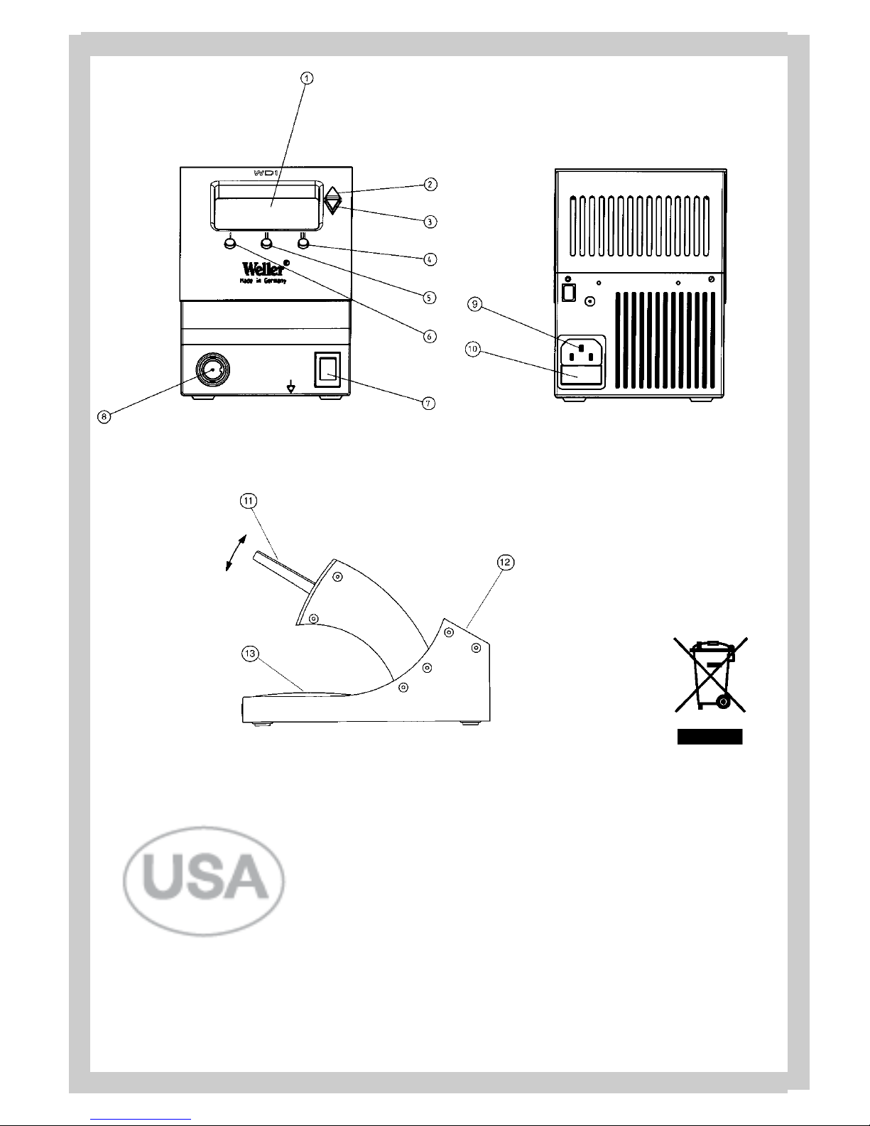
1. LCD Display
2. UP Scroll Key
3. DOWN Scroll Key
4. Radio Button III
5. Radio Button II
6. Radio Button I
7. Power Switch
8. Soldering Iron Receptacle
9. Power Unit Receptacle
10. Primary Fuse
11. Soldering Tool Holder
12. Soldering Stand ( Tip Storage )
13. Tray / Sponge
11.. WWDD11 EExxppllooddeedd VViieew
w
1
1

2
2
Thank you for placing your trust in our company by
purchasing the Weller WD1 / WD1001 / WD1002. This
product meets or exceeds the requirements established by Weller for superior performance, versatility
and quality.
22.. CCaauuttiioonnss!! // WWaarrnniinnggss!
!
Please read these Operating Instructions and the
attached Safety Information carefully prior to initial
operation. Failure to observe the safety warnings may
result in accident, injury, or risk to health.
The manufacturer shall not be liable for damage resulting from misuse or unauthorized alterations of the
equipment.
Warning: This product when used for soldering and
similar applications, produces chemicals known to the
State of California to cause cancer and birth defects or
other reproductive harm.
SSaaffeettyy IInnffoorrmmaattiioonn:
:
● Always place the soldering iron in its original
holder
● Remove all inflammable objects from the proximity of the hot soldering tool.
● Use suitable protective clothing to prevent the risk
of burns associated with molten solder.
● Never leave a hot soldering iron unattended.
● Never work on electrically live circuits or com-
ponents.
● Always wear eye protection when working with
soldering and desoldering applications.
The Weller microprocessor-controlled soldering station
WD1 / WD1001 / WD1002 corresponds to the EC
Declaration of Conformity in accordance with the basic
safety requirements of Directives 89/336/EEC and
73/23EEC.
33.. DDeessccrriippttiioon
n
33..11 CCoonnttrrooll UUnniit
t
The WD Series microprocessor-controlled soldering
stations were developed for industrial electronic production, including repair and laboratory applications.
Digital electronic controls, a precision sensor and heat
transfer technology in the soldering tool provides precise temperature control of the soldering tip.
Fast and precise sensor sampling in the closed loop
control provides tip temperature accuracy and maximum temperature control under load. The soldering
tools are recognized automatically by the WD1 and the
appropriate control parameters are set.
A Factory Control Check function, an Offset value input
option, programmable temperature decrease (Setback )
along with Standby and Lock functions enhance the
functionallity of this unit.
The desired temperature can be set in the range
150 °F – 850 °F (50 °C – 450 °C). “Set” and “Read”
(actual tip temperature) values are displayed digitally.
Three Radio Buttons (4) (5) (6) are used for selection of
fixed/preset temperatures. The Heater Control
Indicator flashes (“
~” symbol in the display) when
the “Set” temperature is reached.
33..22 TTooooll SSttaannd
d
When not in use, the soldering iron should always be
placed in the Tool Stand.
The Tool Holder (11) for the soldering iron has four different settings, (30-80°) and can be moved to an operator’s preferred position without the use of tools. Areas
have been provided on the rear (12) of the Tool Stand
for placing the soldering tip when not in use. The base
of the Tool Stand contains a sponge (13) for cleaning
the soldering tips. (Note: LT tips require tip retainer for
storage in Tool Stand.)
33..33.. SSoollddeerriinngg IIrroonns
s
WWPP8800 (( WWDD11000022 )) :
:
The WP80 Soldering iron is characterized by fast heatup and precise control of the soldering tip. Due to its
slim design, 80W heater output and short reach (tip to
grip), this tool can be used for a variety of applications,
from extremely fine soldering tasks to those requiring
high temperatures.
WWMMPP (( WWDD11000011 )) :
:
The WMP Micro Soldering Iron’s very fast heat-up time
and short reach (tip to grip), makes it ideal for precision SMT electronics. The short distance between the
grip and soldering tip makes precise handling of the
65W soldering iron possible while performing very fine
soldering tasks.
WWTTAA5500 (( OOppttiioonnaall )) :
:
The WTA50 Desoldering Tweezers were designed
specifically for desoldering SMT components. Two
heating elements (2 x 25W),
each with its o
wn temper
ature sensor, maintain the same temperature on both
tweezer tips.
EEnngglliissh
h
3
3
EEnngglliissh
h
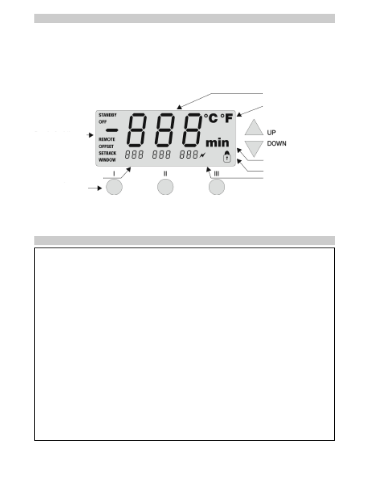
TTeemmppeerraattuurree DDiissppllaay
y
TTeemmppeerraattuurree SSyymmbbool
l
TTiimmee FFuunnccttiioonnss IInnddiiccaattoor
r
SSttaattiioonn LLoocckk IInnddiiccaattoor
r
HHeeaatteerr CCoonnttrrooll IInnddiiccaattoor
r
SSppeecciiaall FFuunnccttiioonns
s
““MMeennuu 11”
”
33 PPrree--SSeelleecctteedd TTeemmppeerraattuurrees
s
33 RRaaddiioo BBuuttttoonns
s
Dimensions: 5.27” L x 4.27” W x 5.77” H; (134mm L x 108mm W x 147mm H)
Primary voltage: 120 VAC / 50/60 Hz
Power Input: 85 Watts
Power Output: 24VAC
Fuse (10): T1.0A (120 VAC) (5 x 20mm)
Temperature Control: 150 °F – 850 °F (50 °C – 450 °C)
Temperature Accuracy: ±17 °F (±9°C)
Temperature Stability: ±9 °F (±5°C)
Tip to Ground Resistance < 2 Ω
Tip to Ground Millivolt Potential < 2 mV
SSccrroollll KKeey
y
SSccrroollll KKeey
y
LCD Display
44.. TTeecchhnniiccaall DDaattaa
4
4
55.. PPllaacciinngg iinnttoo OOppeerraattiioon
n
Take care when unpacking the unit and accessories.
Place the soldering tool in the Tool Holder. Insert the
soldering iron plug into the iron receptacle (8) on the
front of the control unit and lock by turning clockwise.
Verify the supply voltage matches the specification on
the Base Unit Label and that the Power Switch (7) is
Off. Connect the Power Cord into the receptacle (9) on
the rear of the control unit and plug into a properly
grounded power receptacle. Switch On the unit at the
Power Switch (7). The unit performs a self-test when it
is switched “On”, whereby all LCD Icons are briefly displayed (1).
Following the self test, the “Set” temperature is displayed for a brief period. The electronic system then
switches automatically to the “Read” value. The “
~”
symbol appears and the three fixed temperatures of
Radio Buttons
I
I
,
III
I
and
IIIII
I
are displayed. The “~” sym-
bol serves as a Heater Control Indicator. When fully illuminated, the system is heating up. Flashing indicates
the “Set” temperature has been reached and the tool
temperature has stabilized.
55..11 TTeemmppeerraattuurree SSeettttiinng
g
55..11..11 SSeettttiinngg TTeemmppeerraattuurree wwiitthh UUPP//DDoowwnn SSccrroollll KKeeyys
s
As a rule, the main display (1) shows the tip temperature (“Read”) value. By depressing the
UUP
P
or
DDOOWWN
N
Scroll Keys (2 & 3), the display switches to the current
“Set” value. The temperature symbol flashes
°°F
F
(or
°°CC)
)
.
The “Set” value can now be changed by tapping or
holding in the
UUP
P
or
DDOOWWN
N
Scroll Key (2) (3). If the
Scroll Key is held depressed, the “Set” value changes
rapidly. Approximatly 2 seconds after the button is
released, the display switches automatically back to
the “Read” value.
55..11..22 SSeettttiinngg TTeemmppeerraattuurree wwiitthh tthhee RRaaddiioo BBuuttttoonnss II,, IIII,
,
IIIII
I
The “Set” temperature can also be changed via the 3
Radio Buttons
II,, IIII,, IIIII
I
.
Default settings:
I
I
300 °F ( 150 °C )
III
I
660 °F ( 350 °C )
IIIII
I
720 °F ( 380 °C )
By depressing a Radio Button, the pre-selected value
for that button now becomes the “Set” temperature.
The new value appears for approximatly 2 seconds in
the display and the temperature symbol flashes
°°FF (
(
or
°°CC)
)
. The display then switches back automatically to
the “Read” value.
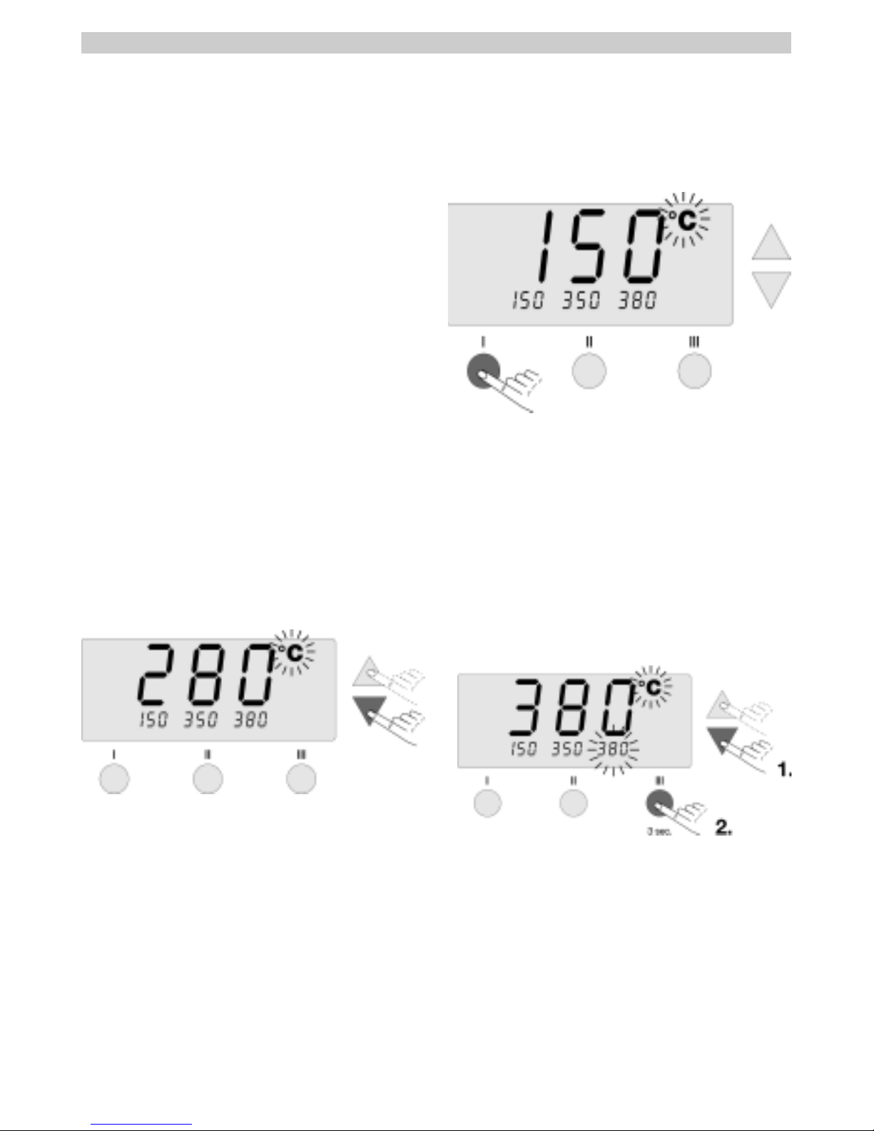
55..11..33 CChhaannggiinngg PPrreesseett VVaalluueess ooff RRaaddiioo BBuuttttoonnss II,, IIII,, IIIIII
The 3 Radio Buttons
II,, IIII,, IIIII
I
can be preset with temper-
ature values as desired.
Depress the
UUP
P
or
DDOOWWN
N
Scroll Key to set a desired
temperature (see 5.1.1) in the large display. The
°°F
F
(or
°°CC))
temperature symbol flashes
.
.
Next, depress and hold the desired Radio Button
II,, III
I
or
IIIII
I
. While the button is depressed, the small display
assigned to the Radio Button also flashes and, after 3
seconds, accepts the value of the large display.
Release the Radio Button.
Setting a Radio Button to a low temperature gives you
the option of manually and quickly decreasing temperature when the soldering iron is not being used.
66.. SSppeecciiaall FFuunnccttiioonns
s
The special functions are divided into two menu sections:
Special Function Menu 1:
Often used functions such as;
STANDBY (Temp.), OFFSET (Temp.), SETBACK (Time),
etc.
Special Function Menu 2:
F
actor
y Control Check (FCC)
and REMOTE ID.
EEnngglliissh
h
5
5
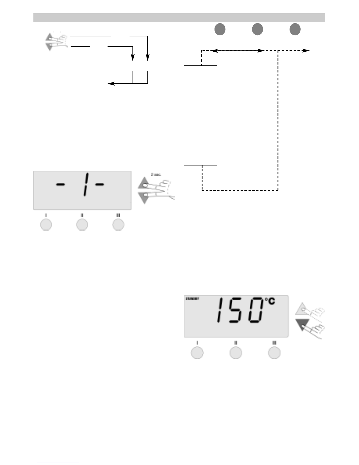
66..11 SSppeecciiaall FFuunnccttiioonnss MMeennuu 1
1
If the
UUP
P
and
DDOOWWN
N
Scroll Keys are depressed simultaneously, after approximately 2 seconds, the menu
selection for the Special Functions is activated and
-- II -
-
appears in the display. Release the Scroll Keys.
The following settings are possible:
OFFSET, STANDBY, WINDOW (temperature settings); SETBACK, OFF (time settings); Lock function (On/Off);
Temperature scale ( °F /°C ).
Radio Buttons
I
I
and
III
I
are used for menu item selection.
Radio Button
IIIII
I
is used to exit the menu.
RReesseettttiinngg tthhee SSttaattiioonn ttoo FFaaccttoorryy SSeettttiinnggss:
:
Depress and hold Radio Button
IIIII
I
. Then depress the
UUP
P
and
DDOOWWN
N
Scroll Keys at the same time. "
FFSSE
E
",
“Factory Setting Enabled” appears in the display. The
soldering station is now reset to its factory default settings.
66..11..11 SSttaannddbbyy TTeemmppeerraattuurre
e
When the Setback time has elapsed, the “Set” temperature is decreased automatically to the Standby value.
The “Read” temperature is displayed (flashing) and
"
SSTTAANNDDBBY
Y
" appears in the display. The Standby temperature can be set in the range ( 200 - 600°F/100 300°C ).
Adjust the Standby temperature with the
UUP
P
or
DDOOWWN
N
Scroll Keys.
Switch to previous menu item with Radio Button
I
I
.
Switch to next menu item with Radio Button
III
I
.
66..11..22 AAuuttoo OOffff TTiimmee ((““OOFFFF””)
)
When the soldering tool is not in use, it is automatically
switched off after the “OFF” time has elapsed. The Auto
Off time can be set from 0 – 999 minutes. With a setting
of "0 min", the Auto Off function is disabled. Auto Off is
carried out independently of the Setback function.
The
“Read” temperature is displayed (flashing) and may be
monitored as a decreasing heat indicator; "
OOFFF
F
"
appears in the display
.
Belo
w 122°F ( 50°C ),
a flashing
dash appears in the center of the display.
EEnngglliissh
h
MMeennuu sseelleeccttiioon
n
EExxiit
t
MMeennuu 1
1
SSTTAANNDDBBY
Y
OOFFF
F
OOFFFFSSEET
T
SSEETTBBAACCK
K
WWIINNDDOOW
W
°°CC//°°F
F
I
I
III
I
IIIIIIEEXXIIT
T
-1- -2-
III (EXIT)
4 sec.
2 sec.
 Loading...