

Weller WD 1, WD 1000, WD 1000M Operating Manual
WD 1 (M) /
WD 1000 (M)
Operating Manual
DE
EN
FR IT ES PT NL SV DK FI GR TR CZ PL HU SK SL EE LV LT
WD 1 (M) / WD 1000 (M)
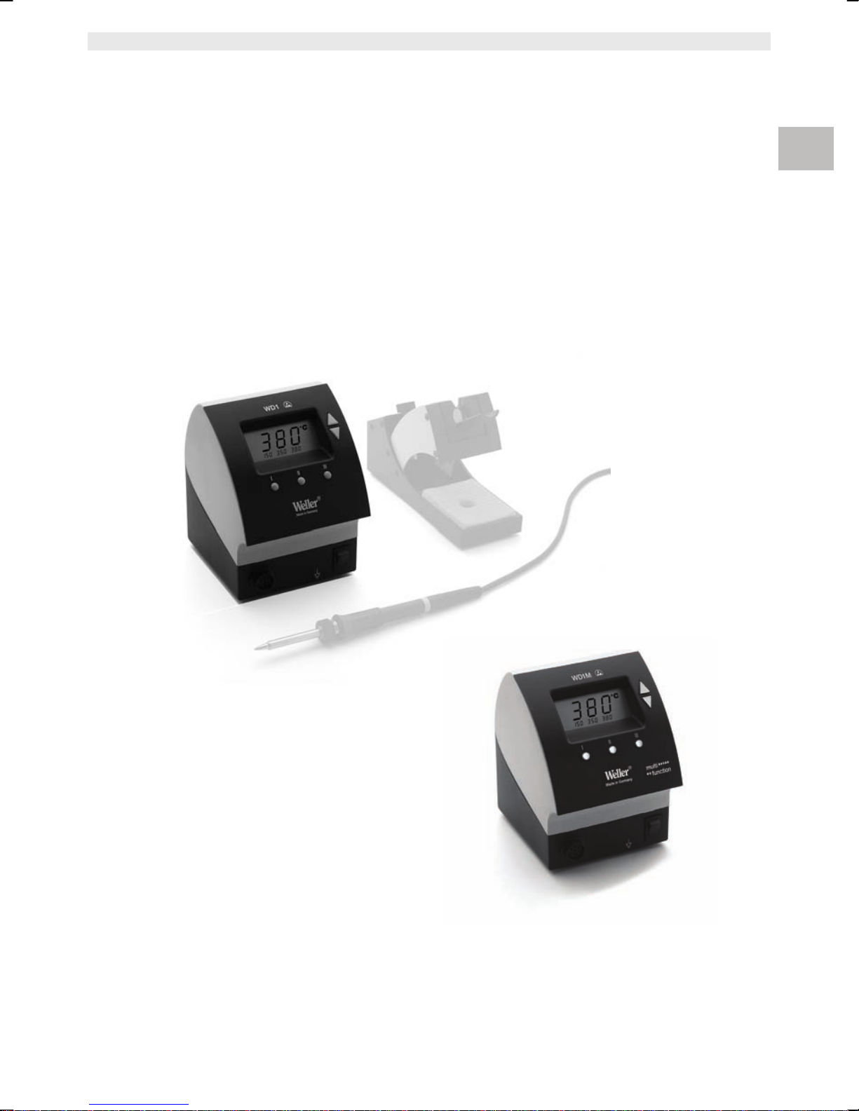
WD 1 (M)
WD 1000 (M)
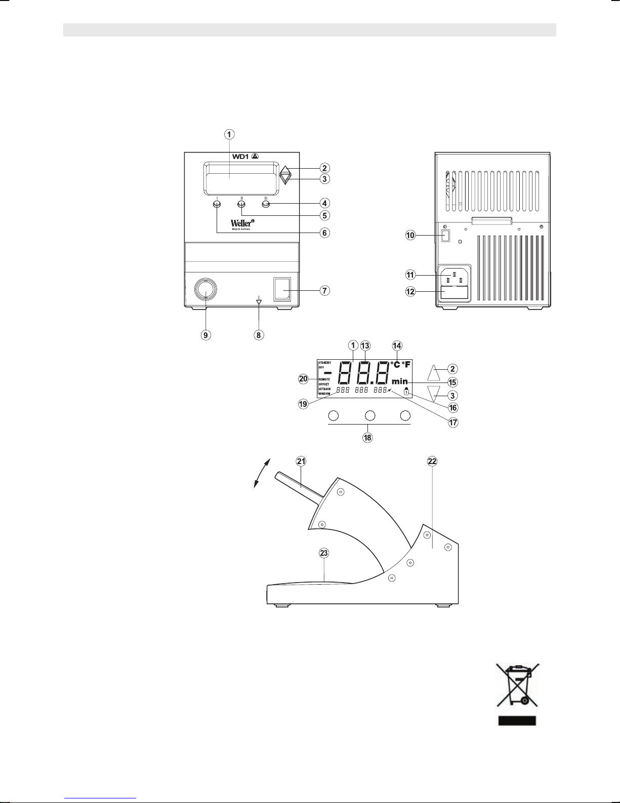
Equipment overview
1 Display
2 UP button
3 DOWN button
4 Temperature button III
5 Temperature button II
6 Temperature button I
7 Mains switch
8 Equipotential-bonding socket
9 Connecting socket for
soldering tool
10 USB interface, B-Mini
(WD 1M)
11 Mains connection
12 Mains system fuse
13 Temperature display
14 Temperature symbol
15 Time function
16 Lock
17 Optical control check
18 Temperature buttons
19 Fixed temperature display
20 Special functions
21 Funnel insert
22 Soldering tip compartment
23 Cleaning element
I II III

WD 1 (M) / WD 1000 (M) 3-18
Contents
About these instructions ............................................................ 3
1
2 For your safety ........................................................................... 4
3 Scope of supply ......................................................................... 4
4 Device description ..................................................................... 5
5 Starting up the device ................................................................ 7
6 Operating the device .................................................................. 8
7 Special functions ........................................................................ 9
8 Resetting to factory settings ...................................................... 17
9 WD 1 (M) / WD 1000 (M) care and maintenance ...................... 17
10 Fault messages and fault elimination ........................................ 17
11 Accessories ............................................................................... 18
12 Disposal ..................................................................................... 18
13 Warranty .................................................................................... 18
DE EN FR IT ES PT NL SV DK FI GR TR CZ PL HU SK SL EE LV LT
1 About these instructions
Thank you for placing your trust in our company by purchasing
the Weller WD 1 (M) / WD 1000 (M). The device has been
manufactured in accordance with the most rigorous quality
standards, which ensure that the device operates perfectly.
These instructions contain important information for safe and correct
initial operation of the WD 1 (M) / WD 1000 (M) soldering station,
including continued operation, maintenance and self-correction of
simple faults.
Z Read these instructions and the accompanying safety information
carefully before switching on the device and starting work with
the WD 1 (M) / WD 1000 (M) soldering station.
Z Make sure that all users have access to these instructions.
1.1 Applied directives
The Weller microprocessor-controlled WD 1 (M) / WD 1000 (M)
soldering station conforms to the specifications of the EC
Declaration of Conformity with Directives 2004/108/EC and
2006/95/EC.
1.2 Documents also applicable
− Operating instructions for soldering station
WD 1 (M) / WD 1000 (M)
− Safety information booklet accompanying these instructions

4-18 WD 1 (M) / WD 1000 (M)
r
r
2 For your safety
The WD 1 (M) / WD 1000 (M) soldering station has been
manufactured in accordance with state-of-the-art technology and
recognised technical safety regulations. There is nevertheless the
risk of personal injury and damage to property if you fail to observe
the safety information set out in the accompanying booklet and the
warnings given in these instructions. Always pass on the
WD 1 (M) / WD 1000 (M) soldering station to third parties together
with these operating instructions.
2.1 Specified use
Use the WD 1 (M) / WD 1000 (M) soldering station exclusively for
the purpose indicated in the operating instructions of soldering and
unsoldering under the conditions specified here. Specified use of the
WD 1 (M) / WD 1000 (M) soldering station also includes
− observing these operating instructions,
− observing all other accompanying documentation,
− observing locally applicable accident prevention regulations.
The manufacturer shall not be liable for damage resulting from
unauthorised alterations to the machine.
3 Scope of supply
WD 1 WD 1000 WD 1M WD 1000M
Control unit a a a a
Power cable a a a a
Jack connecto
Soldering iron a a a
Safety holde
USB cable a a
Operating
instructions
Safety information
booklet
a a a a
a a a
a a a a
a a a a

WD 1 (M) / WD 1000 (M) 5-18
4 Device description
The Weller WD 1 (M) / WD 1000 (M) is a versatile soldering station
for performing professional repair work on state-of-the-art electronic
assemblies in the industrial engineering sector as well as repair
workshops and laboratories.
Precise temperature control performance at the soldering tip is
guaranteed by the digital control electrotechnology together with
superior-quality sensor and heat-transfer technology. High-speed
measured-value acquisition provides for maximum temperature
precision and optimum dynamic temperature performance in load
situations.
All soldering irons (except for microtools) up to 80 Watts can be
connected to the WD 1. The temperature range is from 50 °C to
450 °C (150 °F to 850 °F). The WD 1M is multifunctional and all
soldering irons up to 150 Watts and microtools (WMRP & WMRT)
can be connected; the temperature range is from 50 °C to 450 °C
(150 °F to 850 °F). Setpoint and actual values are displayed in digital
from. Three temperature buttons are used to select fixed
temperatures directly. A flashing optical control check ("a" symbol
on display) indicates that the preselected tool temperature has been
reached.
The Weller WD 1 (M) / WD 1000 (M) soldering station also offers the
following functions:
− Automatic tool detection and activation of corresponding control
parameters
− Digital temperature control
− Option of inputting offset values
− Programmable temperature reduction (setback)
− Standby and lock functions
− Antistatic device design in accordance with ESD safety
− Different equipotential-bonding possibilities on the device
(standard configuration hard earthed)
− Customer-specific calibration function
− USB port for control, evaluation and documentation via PC
DE EN FR IT ES PT NL SV DK FI GR TR CZ PL HU SK SL EE LV LT
4.1 Safety holder
The funnel insert (21) for holding the soldering iron has four different
settings and can be adjusted to the most ergonomic position without
requiring tools. There is a compartment (22) on the back for storing
soldering tips. The base plate on the compartment contains a
cleaning element (23) for cleaning the soldering tip.
6-18 WD 1 (M) / WD 1000 (M)
A
A
4.2 Technical data WD 1 (M) / WD 1000 (M)
Dimensions L x W x H (mm): 134 x 108 x 147
L x W x H (inches): 5.27 x 4.27 x 5.77
Weight approx. 3.4 kg
Mains supply voltage 230 V, 50/60 Hz
120 V, 60 Hz
100 V, 50/60 Hz
Power consumption 95 W
Safety class I and III, housing antistatic
Fuse (12)
Only WD 1 / WD 1000
Fuse (12)
Only WD 1 M/ WD 1000M
Temperature control 50 °C – 450 °C (150 °F – 842 °F)
Temperature accuracy ± 9 °C (± 17 °F)
Temperature stability ± 5 °C (± 9 °F)
Soldering tip leakage
resistance (tip to ground)
Soldering tip leakage
current (tip to ground)
Equipotential bonding Via 3.5 mm pawl socket on back of
T 500 mA (230 V, 50 / 60 Hz)
T 1.0 A (120 V, 60 Hz)
T1.25
T 800 mA (230 V, 50 / 60 Hz)
T 1.6 A (120 V, 60 Hz)
T1.6
Complies with IPC-J-001D
Complies with IPC-J-001D
device (8).
(100 V, 50/60 Hz)
(100 V, 50 Hz)
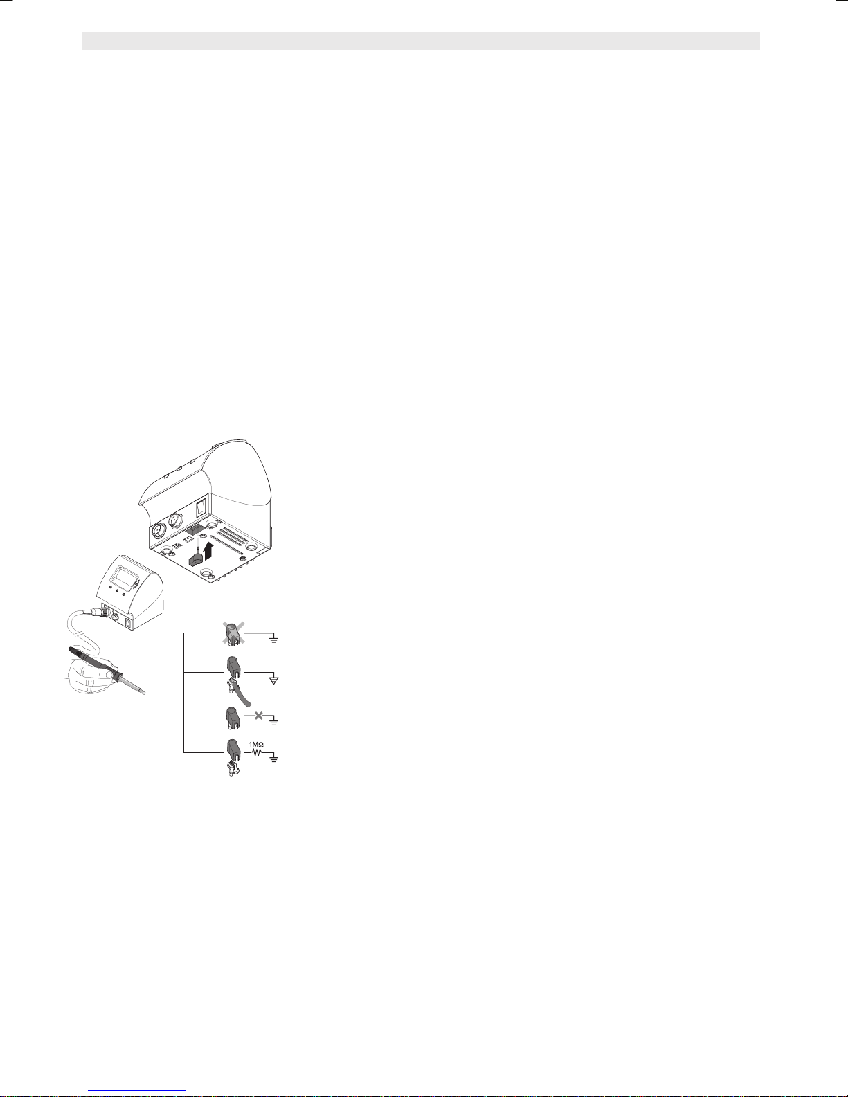
Equipotential bonding
4 variants are possible through connecting the 3.5 mm pawl
socket (8) differently:
− Hard earthed/grounded: without connector (delivery status)
− Equipotential bonding: with connector, bonding line at central
contact
− Floating: with connector
− Soft earthed/grounded: with connector and soldered resistor.
Earthing/grounding via the selected resistor
USB port
The control units WD 1M and WD 1000M are fitted with a mini USB
interface (10). For the purpose of using the USB port, Weller
software is available on a CD with which you
− can carry out a software update ("Firmware Updater“) on your
control unit and
− can remote-control the control unit and graphically display, store
and print temperature curves ("Monitor Software“).
Note Control units WD 1 and WD 1000 can be retrofitted with a USB
interface.

WD 1 (M) / WD 1000 (M) 7-18
WARNING!
5 Starting up the device
Electric shock and risk of burns
Connecting the control unit incorrectly poses a risk of injury and
damage to the device. Risk of burns from the soldering tool while
the control unit is operating.
Z Read the enclosed instructions, the safety instructions included
in these Operating Instructions as well as the instructions for
your control unit all the way through and observe the specified
precautionary measures before operating the control unit.
Z Always place the soldering tool in the safety holder when not in
use.
1. Carefully unpack the device.
2. Connect the soldering tools as follows:
Insert the soldering tool with connector into the connecting socket
(9) on the control unit and turn clockwise to lock.
3. Place the soldering tool in the safety holder.
4. Check whether the mains supply voltage matches that indicated
on the rating plate and whether mains power switch (7) is off.
5. Connect the control unit to the mains supply (11).
6. Switch on the device at the mains power switch (7).
After the device has been switched on, the microprocessor carries
out a self-test in which all the display elements are briefly in
operation. The preset temperature (setpoint) and the temperature
unit (°C / °F) are then displayed briefly. The electronics automatically
switch to the actual value display. The symbol "
the display (1) as an optical control check:
− Continuous illumination indicates that the system is warming up.
− Flashing light indicates that the preselected temperature has been
reached.
" (17) appears on
DE EN FR IT ES PT NL SV DK FI GR TR CZ PL HU SK SL EE LV LT
Note Please refer to the accessories section on page 18 for a list of tools
that can be connected to the WD 1 (M) / WD 1000 (M).
 Loading...