

Page 1

MODEL EC1302B ELECROSTATIC DISSIPATIVE 20 WATT SOLDERING TOOL
PRODUCT DESCRIPTION
The Weller EC1302B series tools feature stainless steel heater construction, a non-burning silicone rubber cord and a large selection of iron plated
copper tips in various styles. The handle design is lightweight, high impact plastic, with controlled thermal conductivity to allow continuous use
without discomfort from heat or fatigue. The heating element is a fast response, long life, nichrome wound unit encased in stainless steel to
eliminate corrosion at high temperature.
The Weller EC1302B tools are interchangeable without recalibration of the soldering station. This is made possible by the use of a high precision
platinum temperature sensor; which is positioned deep inside the tip to insure rapid response to soldering load variations.
The Weller EC1302B tool has been specifically designed for use at electrostatic free workstations and is completely free from stored static charges.
The blue plastic used in this product meets the requirements for ELECTROSTATIC PROTECTIVE MATERIALS as required in Mil-B-18705. The
blue plastic material passes STATIC DECAY tests per Federal Test Method Std. No. 103C, method 4046, and SUFACE RESISTIVITY test per
ASTM D257. All Weller ESD tools comply with DOD-HDBK-263.
The Weller EC1302B tool is designed to be used with the DEC1000, EC1000, EC2000, HYC3000, MC5000 and WTL1000 series power units. The
station and tool combination meets DOD-STD-2000, Mil-S-2000, Mil-S-45743, W-S-6536 and W-S-570, as well as DOD-STD-1686.
SPECIFICATIONS
1. Wattage: 20 watts at 24VAC.
2. Tip voltage to ground: Less than 2mv RMS to line cord ground pin when used with Weller power units.
3. Tool weight: 0.7 ounces without cord.
4. Tool material: The thermoplastic handle and cord jacket are Electrostatic Dissipative (ESD). Metal parts are stainless steel for corrosion
resistance.
5. Heater type: Fiberglass and ceramic insulated nichrome element. Reverse wound for low leakage and magnetic field cancellation.
6. Tip type: Weller EPH series tips. Copper with heavy iron, nickel and chromium plating for long life. See tip chart.
7. Sensor type: Platinum RTD probe. Fits deep inside tip for rapid response. Precision calibrated for interchangeability.
8. Handle design: Small diameter pencil shape with foam rubber sleeve for low grip temperature and maximum comfort.
9. Tool cord: Black ESD Silicone rubber, burn resistant.
10. Connector: Polarized, 5 pin locking.
11. Recovery time: 10 seconds from 100°F drop with EPH101 tip at 700°F.
EC1302B SERIES SOLDERING TOOL TROUBLESHOOTING GUIDE
CAUTION: Disconnect from power supply before attempting repairs.
NOTE: If ground pin has been removed from power unit line cord, tip temperature control may be erratic.
1. Tool does not heat. Possible problems: High resistance or open heater and/or cord.
1.1 Check heater resistance from pin 1 to pin 2 of tool connector. Correct heater resistance is 29 - 32 ohms at ambient temperature.
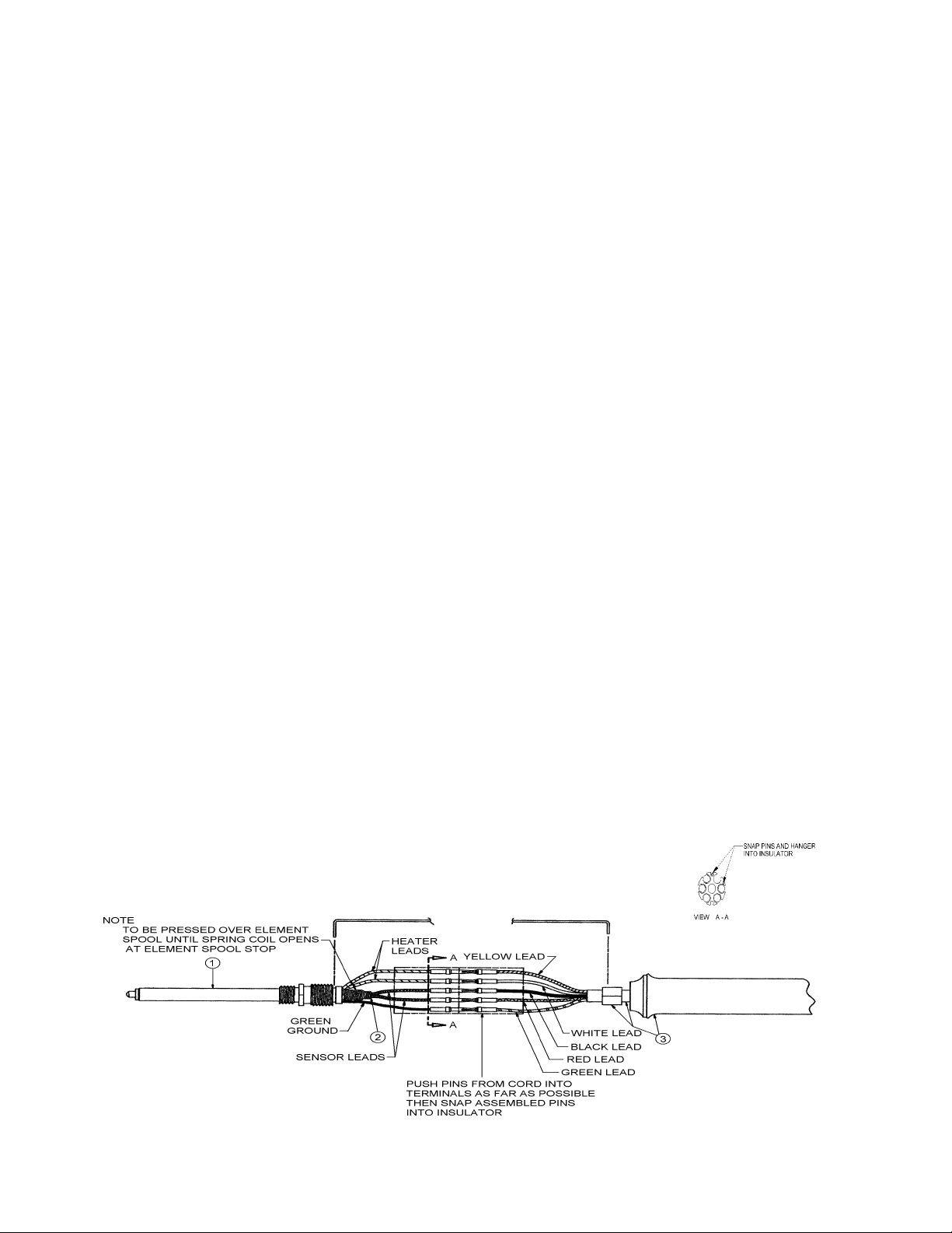
1.1.1 If incorrect, unscrew heater assembly from handle.
1.1.2 Disconnect heater leads from white and yellow cord leads. With cord detached, check heater resistance between pins (29 - 32
1.1.3 Replace heater assembly and/or cord if resistance is incorrect.
1.2 Check sensor resistance from pin 3 to pin 4 of tool connector. Correct sensor resistance is 21 - 24 ohms.
1.2.1 If incorrect, unscrew heater assembly from handle.
1.2.2 Disconnect sensor leads from red and black cord leads. With cord detached, check sensor resistance between pins (21 - 24
1.2.3 Replace sensor and/or cord if resistance is incorrect.
2. Tool overheats. (Note: Tool will overheat with tip removed). Possible problems: low resistance or shorted sensor and/or cord.
2.1 Check sensor resistance from pin 3 to pin 4 of tool connector. Correct sensor resistance is 21 - 24 ohms at ambient temperature.
2.2 If incorrect, unscrew heater assembly from handle.
2.3 Disconnect sensor leads from red and black cord leads. With cord detached, check sensor resistance between pins (21 - 24 ohms is
correct) and cord resistance for shorts between pins pin 3 - pin 4 at connector must measure 3/8 - 3.9K).
2.4 Replace sensor and/or cord if resistance is incorrect.
3. High voltage on tip. Possible problems: open heater and/or cord ground lead or short between heater and ground lead.
3.1 Check ground circuit resistance from tip to pin 5 on connector. Correct resistance is less then 1 ohm.
3.1.1 If greater than 1 ohm, unscrew heater assembly from handle.
3.1.2 Disconnect green heater ground lead from green cord lead. With cord detached, check ground resistance between pin and tip
3.1.3 Replace heater assembly and/or cord if resistance is incorrect.
3.2 Check heater to ground resistance between pin 5 and pin 1 or pin 2. Correct resistance is infinity.
3.2.1 If incorrect, unscrew heater assembly from handle.
3.2.2 Disconnect green heater ground lead from green cord lead. With cord detached, check ground resistance between a heater pin
3.3 Replace heater assembly and/or cord if resistance is incorrect.
ohms is correct). Cord resistance for opens between pins at connector and pins in handle. (Resistance between pin 1 and pin
connected to yellow lead, and between pin 2 and pin connected to white lead should measure 0 - 0.5 ohms maximum; between
pin 1 and pin 2 must measure infinity).
ohms is correct) and cord resistance for opens between pins at connector and pins in handle (resistance between pin 3 and
pin connected to black lead and between pin 2 and pin connected to red lead should measure 0 - 0.5 ohms maximum; pin 3
and pin 4 must measure 3.8 - 3.9K).
(0 - 0.5 ohms is correct) and cord resistance for open between pin green in handle and pin 5 at connector (0 - 0.5 ohms is
correct).
and ground (green) pin. A measurement of infinity ohms is correct. Check resistance between pin 5 and pin 1 or pin 2. A
measurement of infinity ohms is correct.
Page 2
Weller® EPH series tips are solid copper, plated with iron, nickel and chromium. The nickel and chromium protect the shank from corrosion and
solder creep. The tips are pre-tinned in the working area with solder. Use only Weller soldering tips. Use of non-Weller components may void product
warranty if the non-Weller component causes damage to the unit.
TIP SELECTION CHART
NUMBER DESCRIPTION TIP REACH CATEGORY
EPH101 Micropoint 1/64 7/16 A
EPH102 Bent conical 1/32 7/16 A
EPH103 Single flat 1/32 5/16 A
EPH104 Bent conical 3/64 7/16 A
EPH105 Single flat 3/64 5/16 B
EPH106 Screwdriver 1/16 7/16 B
EPH107 Chisel 5/64 7/16 A
EPH108 Chisel 7/64 7/16 A
EPH109 Conical 1/32 7/16 A
EPH110 Conical 1/16 7/16 A
EPH111 Screwdriver 3/64 7/16 B
1. Keep tip tinned; wipe only before using.
2. Use rosin or activated rosin fluxes. Acid type fluxes will greatly reduce tip life.
3. Remove tip and clean with suitable cleaner for flux used. The frequency of cleaning will depend on the type of work and usage. Tips in
constant use should be removed and cleaned at least once a week. Corrosion between tip and sensor can cause erratic temperature
control.
WARNING: If tip does not remove easily, do not force it. The sensor will be damaged. Try removing the tip while heated. If this does not
4. Dont try to clean tip with abrasive materials other than the Weller WPB1 polishing bar and never file tip; to do so will greatly reduce tip life.
Tip wettability is affected by contact with organics; such as plastic resins, silicone grease, and other chemicals. If the tip becomes
unwettable, it may be cleaned hot with a soft steel or brass brush using solder flux as a solvent or with a Weller WPB1 polishing bar. Do
not over do this or the iron plating will be removed and the tip ruined. Re-tin tip immediately to prevent oxidation.
5. Dont remove excess solder from heated tip before storing. The excess solder will prevent oxidation of the wettable surface when tip is
reheated.
6. Do not use any compound or anti-seize material on Weller tips or sensor probe. They will cause wettability problems and may cause
seizing after long heated periods.
work, return tool to Weller for service. When installing new tips, they should slide freely over sensor probe.
WARNING: This product, when used for soldering and similar applications, produces chemicals known to the State of California to
REPLACEMENT PARTS FOR EC1302B
KEY NO. PART NO. DESCRIPTION
1 EC231 Barrel nut assembly
2 EC259B Heater assembly
3 EC260B Sensor assembly
4 EC256B Handle/Cord
Not Shown TC205 Sponge
Not Shown IHF225EC Spring and funnel
Not Shown PH1301ESD Tool stand
Not Shown WPB1 Polishing bar for tips
cause cancer and birth defects or other reproductive harm.
 Loading...