

Page 1
MODEL DS800 ELECTRONIC DESOLDERING STATION
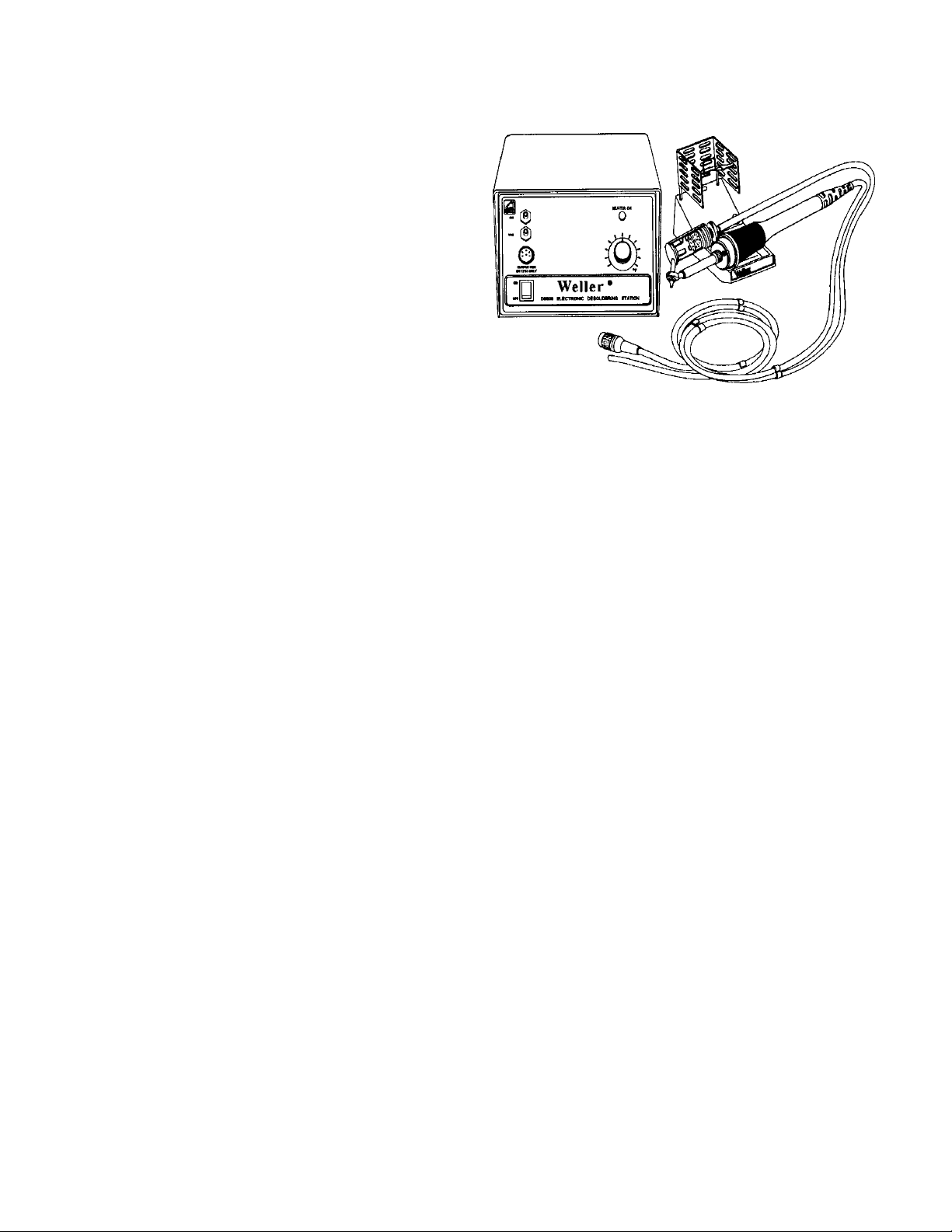
PRODUCT DESCRIPTION
The DS800 is a fully electronic desoldering station with
electrostatic dissipative (ESD) construction and utilizes a
high precision electronic system to control desoldering tip
temperatures. A precision platinum sensor is used in the
desoldering tool to measure temperature. Tools may be
unplugged and replaced without affecting the calibrated
accuracy of the station. Temperature control and dynamic
response to load are fast and noise free. Zero crossing or
optically isolated electronic circuitry is used to control the
pump and other functions so that no voltage transients are
generated to endanger sensitive, high reliability electronic
circuitry. Temperature control is indicated by the flashing LED
which shows when the heating element is on. A calibrated dial
is used to set tip temperature. This covers a temperature
range of 350°F to 850°F.
The DS800 uses an internal rotary vane vacuum pump to supply vacuum for desoldering operations. This pump can provide a
high vacuum for desoldering multi-layer boards and other difficult jobs as well as high flow for very good plated through hole
cooling to prevent reattachment of leads in holes after desoldering. It is also very quite when operating. The desoldering
pencil has a convenient index finger push button to control the vacuum pump. The vacuum pump may also be controlled
using an optional foot switch that plugs into a socket located on the rear of the station housing.
The DS800 uses a new DS1203 desoldering pencil that has a high mass desoldering head and high power heating element.
The high mass head holds more heat and can transfer that heat to the joint being desoldered much faster. This allows faster
desoldering without having to use possibly damaging high tip temperatures to get enough heat.
SPECIFICATIONS: DS800 DESOLDERING STATION
DS800 POWER UNIT
1. Power input: 120 Vac, 60 Hz, 150 watts.
2. Power unit output voltage: isolated 24 VAC (full load) 54 watts at 700°F (371°C).
3. Size: 10.5"D x 6.75"W x 4.75"H
4. Line Cord: 2 wire, U.L. approved
5. Desoldering Tip Temperature Control Range: 350°F (177°C) to 850°F (454°C).
6. Control Setting Resolution: ± 10°F (±10°C).
7. Control Accuracy: ± 10°F (±6°C) of setting at idling temperature
8. Ambient Range: 60 °F (15°C) to 110°F (43°C)
9. Vacuum Source: Internal high performance rotary vane pump. 24 inch HG/typical with tiplet blocked.
10. Cord Connectors: 7 pin polarized (desoldering tool), 2 pin polarized (optional foot switch control).
11. The DS800 Electronic Desoldering Station is fully UL approved and meets the following military specifications:
DOD-STD-2000, MIL-S-45743, W-S-570, DOD-STD-1686, AND DOD-HDBK-263.
WARNING: DO NOT REMOVE GROUND PRONG FROM LINE CORD PLUG. REMOVAL OF GROUND
PRONG WILL CAUSE TIP TEMPERATURE CONTROL TO BE ERRATIC.
Page 2

DS1203 DESOLDERING TOOL (PENCIL TYPE).
1. Wattage 54 watts @ 700°F (371°C).
2. Tiplet Voltage to Ground: 2 mv RMS Leakage @ 60 Hz Max.
3. Tool Weight: 4.8 oz. (136 grams)
4. Tool Material Thermoplastic handle (ESD material), stainless steel heating element housing, platinum tempera ture sensor, nichrome heating element, solid copper head.
5. Thirteen sizes and styles of replaceable tiplets available.
6. Platinum R.T.D. (resistance temperature detector) probe fits deep inside desoldering head.
7. Integrated heating element and desoldering head with plug in design for quick replacement.
8. Heater Type: Fiberglass and ceramic insulated, nichrome, reverse wound for low leakage and magnetic field
cancellation. Encased in 300 series stainless steel. Modular plug in design.
9. Large easily cleaned visible solder reservoir.
10. Lightweight pencil design with forefinger push button for vacuum actuation.
11. Tool cord and vacuum hose silicone rubber 4 ft.
POWER DESOLDERING METHOD
The recommended desoldering technique for P.C. boards is to heat the soldered connection with the component lead end
inside the tiplet until the solder is visually melted. This should take 1 to 5 seconds depending on the particular connection
being desoldered. The tiplet surface should be held flush with the P.C. board pad during heating and desoldering. Addition of
a small amount of flux core solder will sometimes improve this process. As the solder melts, the tiplet should be moved with
a circular motion.
This movement will cause the component lead to move around in the P.C. board hole. Depress the push button and hold it
depressed while continuing to rotate the tiplet for 1 - 2 seconds. Remove the tiplet from the pad and then release the push
button, The movement of the lead in the hole and subsequent cooling of pad and lead to below solder melt temperature will
prevent the remaining solder on the pad and lead surfaces from solidifying together. This technique is definitely required when
desoldering plated through holes on double or multi-layer P.C. boards.
USING DESOLDERING HEAD FOR HOT AIR HEATING
WARNING: BE SURE TO REMOVE ALL THE SOLDER FROM THE TIPLET, GLASS TUBE, AND CONNECTOR
TUBE BEFORE USING THE TOOL FOR HOT AIR APPLICATIONS. NEVER DIRECT HOT AIR
TOWARD ANY PART OF YOUR BODY OF OTHER PEOPLE.
It is recommended that a separate desoldering head be used for hot air applications to eliminate the need for thorough
cleaning before using, however, the following procedure will insure that no solder is left in the tool.
PROCEDURE FOR CONNECTING THE TOOL FOR HOT AIR USE:
1. Turn the unit on and allow it to heat (3 minutes minimum).
2. With tube connected to vacuum, hold the tool vertical with the tiplet up and actuate the vacuum source ten
seconds.
3. Insert a tip cleaning tool in the tiplet and force it through into the solder collection chamber with vacuum present.
4. Hold the tool vertical and operate the push button for 5 seconds, then switch the unit off and continue to hold the
tool vertical until the tiplet cools at least below solder melting temperature.
5. Remove tiplet and clean end. Remove the glass tube and clean all solder from it. Check delivery tube and remove
solder. Remove the cotton filter. Replace glass tube. Make sure the gaskets are properly seated. Tighten sealing
nut finger tight. Replace tiplet.
6. Connect the rubber tube connected to the vacuum fitting to the air fitting.
7. Turn the unit on and wait 3 minutes for heat up.
Page 3

DSH219 DESOLDERING HEAD
Each desoldering iron has been provided with a cotton filter in the
collector tube. NEVER operate a desoldering iron without the filter in
place. The purpose of the filter is to prevent solder from entering and
clogging the vacuum tube or pump. Cotton has proven to be the best
material for this filter. See DS204 in parts list. Do not use spun
synthetic materials, such as rayon, because they will not withstand
the temperature in the desoldering head.
Each desoldering head is provided with two gaskets, a teflon sponge
gasket for the front of the collection tube and a neoprene rubber
gasket for the other end. The gaskets require periodic replacement
depending on use. Attempting to use the desoldering head without
both gaskets in place will cause a vacuum leak and result in poor
POWER DESOLDERING HEAD
desoldering head performance.
The glass collector tub should be handled with care. Remove the tube with the tube extractor provided. Allow the tube to cool
before attempting to clean and replace it into the head. Care should be taken to avoid dropping the tube onto the floor - it will
break. Do not tap the tube with pliers or a screwdriver, this might cause the edge of the tube to break.
Iron plated copper tiplets should be reamed out with the clean out tool approximately once every 15 minutes of operation.
Clogging may be experienced inside the stainless steel tiplet liner due to solder dross sticking to the liner preventive
maintenance with tiplets is important for trouble free desoldering.
VACUUM FILTER
The vacuum filter must be checked monthly for flux buildup. Flux fumes from desoldering will condense in the filter and slowly
restrict air flow. Access to the filter is from the bottom of the unit. The filter consists of a plastic foam element and a stainless
steel sponge pad. Both elements may be cleaned in alcohol or flux cleaner, dried and replaced.
TIPLETS FOR DESOLDERING TOOLS
The desoldering tiplets used on the DS1203 high mass desoldering tool are threaded designs. Thirteen sizes are available.
The DS800 comes with five high mass tiplets. There are also eight standard tiplets available. The high mass tiplets hold more
heat than the standard tiplets and can transfer more heat to handle heavy multi-layer P.C. boards. This makes desoldering
faster and there is less chance of burning the P.C. board. All tiplets are iron plated for good wettability and long life. Additional
plating of nickel and chrome are applied to protect the iron plating from oxidation and prevent solder from creeping up the
outside of the tiplet. All the desoldering tiplets useable with the DS1203 iron are shown in the next table.
AVAILABLE DESOLDERING TIPLETS FOR DS1203 IRON
STANDARD DIMENSIONS HIGH MASS DIMENSIONS
TIPLETS A B C TIPLETS A B C
DS110 .025 .060 .50 DSH110 .025 .060 .75
DS111 .025 .090 .50 DSH111 .025 .090 .75
DS112 .036 .076 .50 DSH112 .025 .076 .75
DS113 .045 .098 .50 DSH113 .045 .098 .75
DS114 .071 .125 .50 DSH114 .071 .125 .75
DS115 .025 .060 .75
DS116 .045 .098 .75
DS117 .025 .090 .75
Page 4

ACCESSORIES AND REPAIR PARTS FOR DS800 DESOLDERING STATION
(Please state product model number when ordering these parts from you original supplier)
PART NUMBER DESCRIPTION
DS1203A High Power Desoldering Tool
DS2010 Desoldering Tool Stand w/Holder
DSH54 54 Watt Heater Assembly for DS1203
DSH219 High Mass Desoldering Head
DS103 Collector Tube w/Gaskets and Filter
DS204 Filters for Desoldering Head
DS205 In-Line Filter
DS209 Tiplet Clean Out Tools
DS211 Gaskets for Desoldering Head
SHA3 Cushion Grip Sleeve for Iron Handle
TC205 Sponge
CUSTOMER SERVICES
Should your DS800 require repair or adjustment if may be sent to the following address:
Cooper Tools - Weller Division
1000 Lufkin Road
Apex, NC 27539
ATTN: Repair Department
©1991 Cooper Industries, Inc.
S748
8/91
Rev. 3/03
 Loading...