

Page 1
R
1.0
0.5
Ya - mmho
0
-400
-200
PRESSURE - DaPa
TEST
Portable
Tympanometric
2
GR
A
1
GR
C
+200 Vea - cc
0
200
L
Instrument
POWER
CHARGE
FEED
PRINT
Operating
Instructions
Page 2

Acknowledgments
Welch Allyn gratefully acknowledges the assistance of Robert H. Margolis,
Ph.D. of the University of Minnesota for his assistance in preparing the Guide
to Tympanometry and Glossary sections of this manual.
Trademarks
Welch Allyn and MicroTymp are registered trademarks of Welch Allyn, Inc. in
the United States and other countries.
Patents
MicroTymp – U.S. Patent Number 4,688,582
Conductive Path ESD Shield – U.S. Patent Number 5,383,097
Page 3

Contents
MicroTymp2 – Introduction
MicroTymp2 Handle Components .............................................................2
MicroTymp2 Printer/Charger Components ................................................3
Preparing to Use the MicroTymp2 Handle and Printer/Charger................ 3
Setting up the MicroTymp2 Handle and Printer/Charger ...................... 4
MicroTymp2 – Completing a Test
Obtaining a Tympanogram.........................................................................5
Selecting a Probe Tip .............................................................................5
Testing....................................................................................................6
Storing and Erasing Data .......................................................................7
Displaying Memory Contents .................................................................8
Erasing Memory Contents......................................................................8
Understanding the Liquid Crystal Display (LCD) and Its Messages .......... 8
Gradient (Width) Measurements.............................................................8
Printing Memory Contents .......................................................................15
MicroTymp2 Printout Formats..................................................................16
Description of Formats .........................................................................16
Selecting Printout Formats.......................................................................20
Changing from Manual to Automatic Printout ......................................20
Changing Printout Format ....................................................................21
Printer Function Messages ......................................................................23
Printer Service Codes ..............................................................................24
Appendix A – Guide to Tympanometry
Basic Principles of Tympanometry ....................................................... A-25
Tympanogram Characteristics ............................................................. A-26
How the MicroTymp2 Instrument Works..............................................A-27
Normative Values for the MicroTymp2 ................................................. A-28
Interpreting Tympanogram Results ......................................................A-29
Obtaining a Valid Tympanogram ....................................................... A-31
Tympanometry in Young Infants .......................................................A-31
Conditions Which Cause Too Much Artifact.....................................A-31
Conditions Which Artificially Flatten the Tympanogram....................A-32
The Normal Ear ................................................................................ A-33
Low-Admittance Pathologies ...........................................................A-34
Tympanic Membrane Abnormalities .................................................A-36
Conditions Which Cause Negative Middle Ear Pressure ..................A-37
Conditions Which Cause Positive Middle Ear Pressure....................A-37
Appendix B – Guidelines for Screening for Hearing Impairments
and Middle Ear Disorders ..................................................................B-39
Recommended Screening Protocol.....................................................B-41
Audiological or Medical Referral .......................................................B-42
Page 4

Appendix C – Maintaining the MicroTymp2 Equipment
The MicroTymp 2 Battery.....................................................................C-43
Recharging the Battery ....................................................................C-46
Recycling the Battery .......................................................................C-47
Paper Replacement .............................................................................C-48
Cleaning, Disinfection and Sterilization ................................................C-50
Cleaning the MicroTymp 2 Handle ....................................................C-50
Printer/Charger Cleaning..................................................................C-50
Disinfection and Sterilization of the Probe Tips ................................C-50
Appendix D – Functional Checks of the MicroTymp2 Handle
and Printer/Charger
Functional Checks of the MicroTymp 2 Handle ....................................D-51
Troubleshooting the MicroTymp 2 Handle .........................................D-53
Functional Checks of the Printer/Charger............................................D-53
Appendix E – Service and Warranty Information
Service ................................................................................................. E-55
Repair............................................................................................... E-55
Recalibration .................................................................................... E-55
Warranty............................................................................................... E-56
MicroTymp2 Instrument.................................................................... E-56
MicroTymp2 Rechargeable Battery .................................................. E-56
Appendix F – Technical Specifications .............................................. F-57
Appendix G – MicroTymp 2 Replacement Parts and Accessories . G-61
References ................................................................................................63
Glossary .....................................................................................................65
Page 5

MicroTymp2 – Introduction
Thank you for purchasing the Welch Allyn MicroTymp 2 Portable Tympanometric Instrument.
The Welch Allyn MicroTymp2 provides portable tympanometry which is
automatic, easy to use, and offers the following features:
• Measures middle ear function in as little as one second
• Displays results as they happen
• Stores data from two ears before printing
• Prints out hardcopy automatically or on demand in five seconds
With MicroTymp2 tympanometry, objective, printed documentation of otitis
media with effusion and other middle ear disorders is quickly and easily
obtained. This results in more thorough diagnoses, and more effective
monitoring, treatment, parent consultation, and referrals.
Data stored in the memory of the MicroTymp2 Handle may be printed using
the Printer/Charger. The Printer/Charger reads the information from the
Handle and quietly prints out tympanograms from two ears with test results
in five seconds.
The MicroTymp2 Printer/Charger also charges the rechargeable battery in
the MicroTymp2 Handle.
This manual describes how to operate and maintain the MicroTymp2 Handle
and Printer/Charger. Please follow these instructions to ensure many years
of accurate and reliable service. For additional information on the science of
tympanometry, refer to “A Guide to Tympanometry” (Appendix A, page A-25).
1
Page 6
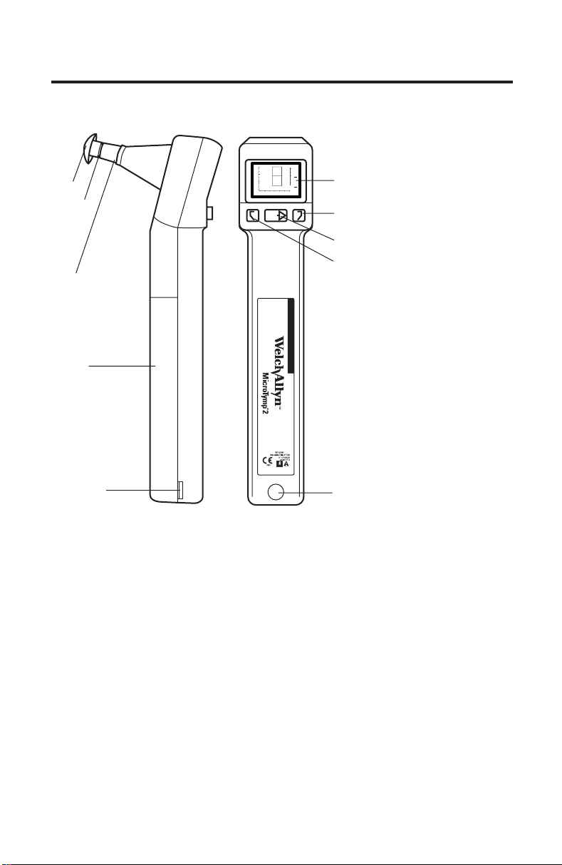
MicroTymp2 Handle Components
2
GR
1.0
A
Tip
Probe
Tip
Ejector
Battery
Cover
0.5
Ya - mmho
0
-400 -200 0 200
PRESSURE - daPa
RLTEST
1
GR
C
+200 Vea - cc
Liquid Crystal
Display (LCD)
Left Memory
Button
Test Button
Right Memory
Button
Charging
Contacts
Infrared Data
Transfer Window
Figure 1A
2
Page 7
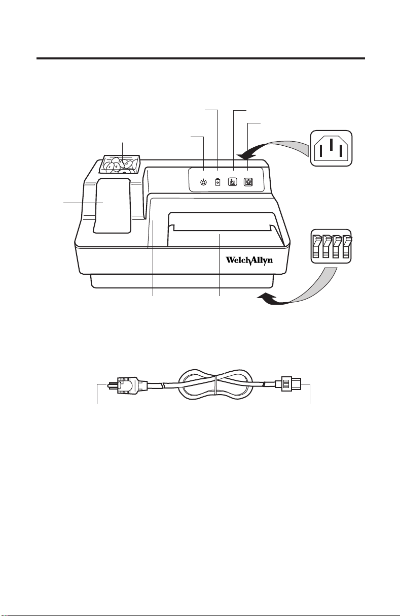
MicroTymp2 Printer/Charger Components
Charging
Well for
MicroTymp2
Tip Box
POWER
Indicator
Paper Access
Cover
CHARGE
Indicator
POWER CHARGE FEED PRINT
Paper
Slot
Power Cord
FEED Button
PRINT Button
TM
IEC Power
Cord Receptacle
Printer/Charger
Switches
134
2
OFF
To Power
Receptacle
To IEC Power
Cord Receptacle
Figure 1B
Preparing to Use the MicroTymp2 Handle
and Printer/Charger
The following is a list of important facts to note before using the
MicroTymp2.
• Please complete and return the warranty registration card. It validates
the warranty, and allows Welch Allyn to communicate recalibration
notices and software changes.
3
Page 8
• If the MicroTymp 2 set has not been stored at room temperature, allow
45 minutes for it to return to operating temperature range (15-35˚C or
59-95˚F) before using.
• Do not store either the MicroTymp2 Handle or Printer/Charger at
temperatures which exceed 66˚C (150˚F). Continual exposure to extremely high temperatures can permanently damage components.
Refer to Operating Instructions manual.
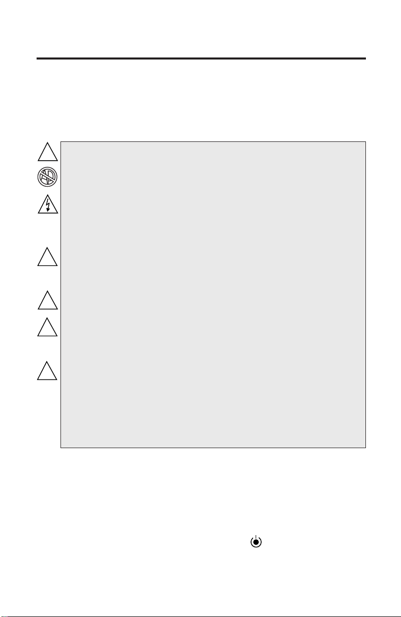
!
DANGER: Explosion risk if Printer/Charger is used with
flammable anesthetics.
CAUTION: Disassembly of the Printer/Charger presents a
possible electrical shock hazard. Refer all servicing to Welch
Allyn or a Welch Allyn authorized service representative listed
on page E-55.
Disassembly of the MicroTymp2 Handle or Printer/Charger
!
beyond the extent described in this manual will void the
warranty. Refer all servicing to Welch Allyn or a Welch Allyn
authorized service representative listed on page E-55.
Disconnect from the mains via the appliance inlet.
!
Charge only MicroTymp 2 Handle (#23640), MicroTymp Handle
!
(#23600), or AudioScope 3 (#23300) in the MicroTymp 2
Printer/Charger.
BATTERY REPLACEMENT: Replace with Welch Allyn model
!
#72900 battery only.
NOTE: The MicroTymp
data from the original MicroTymp Handle. However, the original
MicroTymp Printer/Charger will neither charge nor print data
from the MicroTymp
Stand (#71126) is available for charging only.
2 Printer/Charger will charge and print
2 Handle. A special AudioScope Charging
Setting up the MicroTymp2 Handle and Printer/Charger
• Install the MicroTymp2 rechargeable battery in the Handle by following
the instructions found on page C-43 of this manual.
• Place the Printer/Charger on a flat, horizontal surface.
• Plug the power cord into the receptacle in the rear of the Printer/
Charger. Then connect the power cord to a receptacle of proper voltage,
frequency, and plug type. The green POWER
to indicate that the Printer/Charger is operating properly.
See Figure 1A and 1B (pages 2 and 3).
4
indicator will illuminate
Page 9
MicroTymp2 – Completing a Test
Completing a Test
MicroTymp
Obtaining a Tympanogram
Selecting a Probe Tip
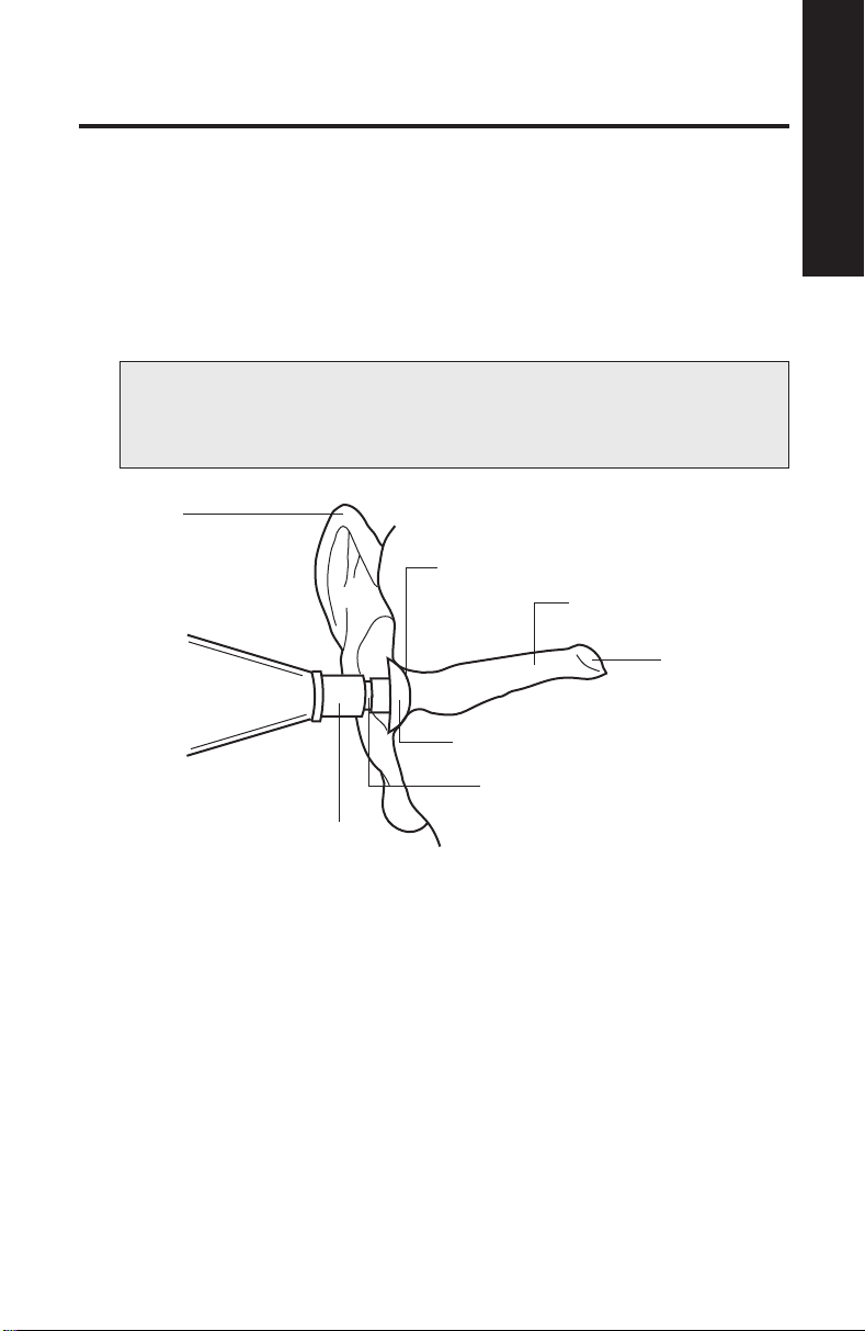
1. After examining the subject’s ear canal opening, select a tip which is
large enough to seal the entrance of the ear canal. See Figure 2.
To change tips, either pull the tip off by hand or slide the tip ejector
towards the tip.
NOTE: Tips are not intended to be deeply inserted into the ear
canal. Using an improper tip size causes leaks, and will make it
difficult to complete a test.
Pinna
Seal
External Ear Canal
Tympanic
Membrane
Tip
Probe
2
Tip Ejector
Figure 2
2. Push the tip onto the probe, making sure that the tip is fully seated.
5
Page 10
Testing
2
A
+200 Vea -
TEST
button below
GR
cc
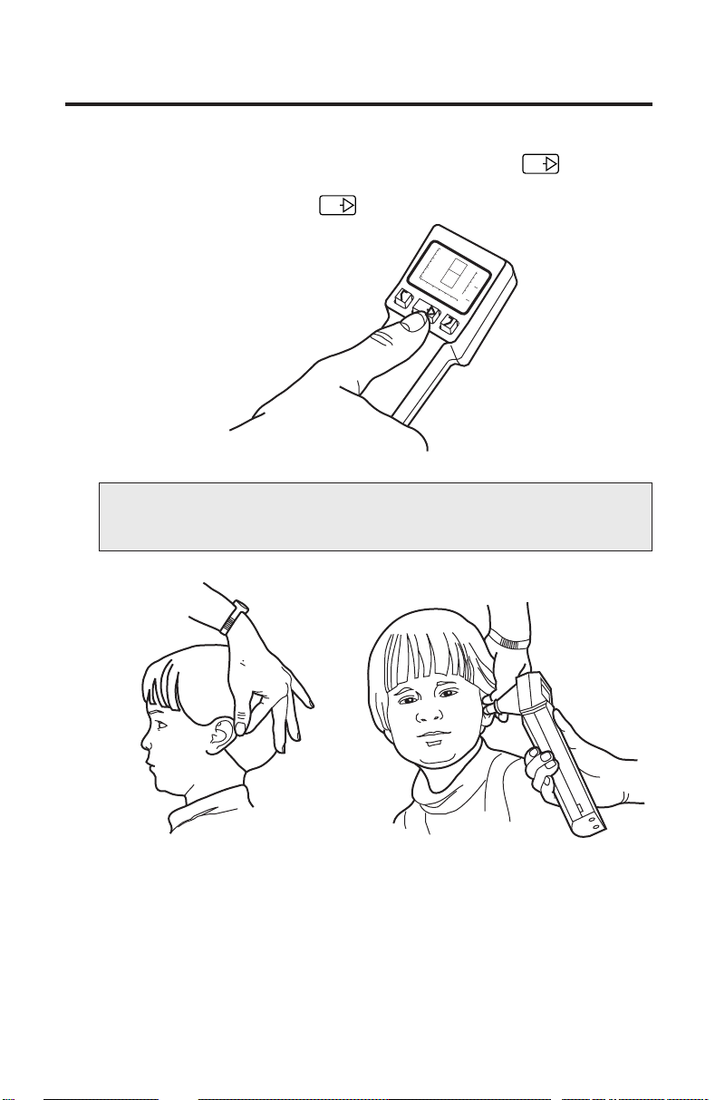
3. Turn on the MicroTymp 2 Handle by pressing the TEST
the Liquid Crystal Display (LCD). The word “OPEN” appears on the LCD.
Figure 3 illustrates the TEST button and the OPEN message.
TEST
1.0
0.5
OPEN
Ya - mmho
0
-400 -200 0 200
1
PRESSURE - DaPa
RL
GR
C
TEST
Figure 3
NOTE: The MicroTymp2 automatically turns off 15 seconds after
the last test or activation of any button.
Figure 4 Figure 5
4. Grasp the subject’s pinna. Pull gently back to straighten the child’s ear
canal (or up and back for adults). See Figure 4.
5. While maintaining tension on the pinna, press the tip firmly against the
ear canal opening. See Figure 5. Point the tip straight into the ear canal
for adults and slightly anteriorly for children.
6
Page 11
Completing a Test
MicroTymp
NOTE: Due to changes in air pressure during a test, the
subject will feel slight pressure in the ear canal. During the
brief seconds when tympanometric measurements are made,
it is important that the practitioner’s hand is steady, and that
the subject does not talk, yawn, chew gum, cry, or make any
other similar movements.
If a seal is not achieved, the LCD will display a LEAK, BLOCK, or OPEN
message. Reposition the instrument to attempt another test.
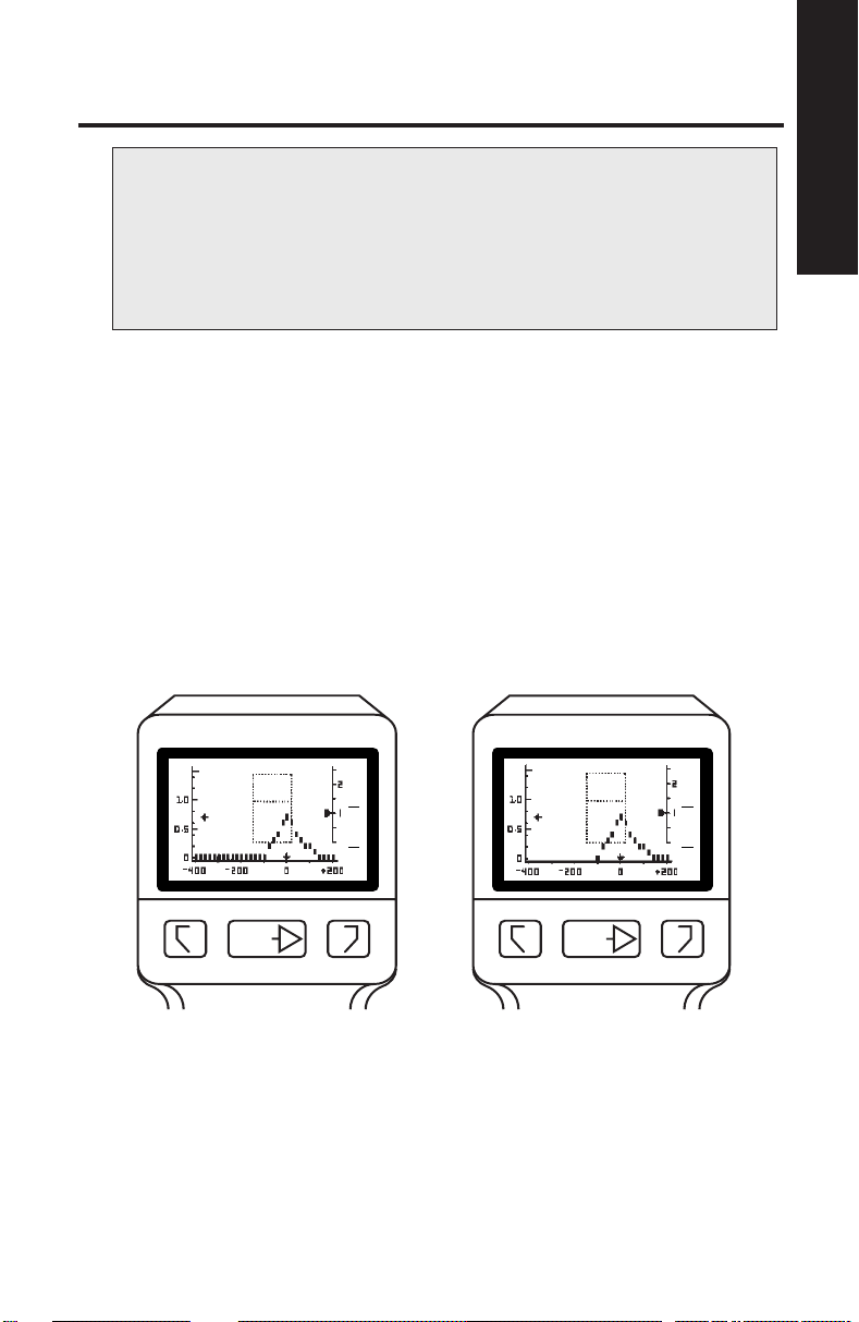
6. Once a seal is achieved, the TEST message appears on the LCD,
followed by the volume indication on the +200 Vea scale. Data points
are then displayed from right to left across the LCD as the test progresses.
If the BLOCK, LEAK, or OPEN messages appear during the test,
reposition the tip to restart the test.
The test is complete when the last data point is displayed. Figure 6A
illustrates the execution of a complete test (approximately 1.8 seconds).
If patient or instrument movement causes a leak beyond -100 daPa,
the test will be stopped (approximately 1.0 seconds), but the data will
be saved. See Figure 6B.
1.0
0.5
Ya - mmho
0
-400 -200 0 200
PRESSURE - daPa
2
1
GR
A
GR
C
+200 Vea - cc
1.0
0.5
Ya - mmho
0
-400 -200 0 200
PRESSURE - daPa
2
GR
A
1
GR
C
2
+200 Vea - cc
RLTEST
RLTEST
Figure 6A Figure 6B
Storing and Erasing Data
7. To store the results of the test, press the button which matches the
tested ear, as illustrated in Figure 7.
7
Page 12
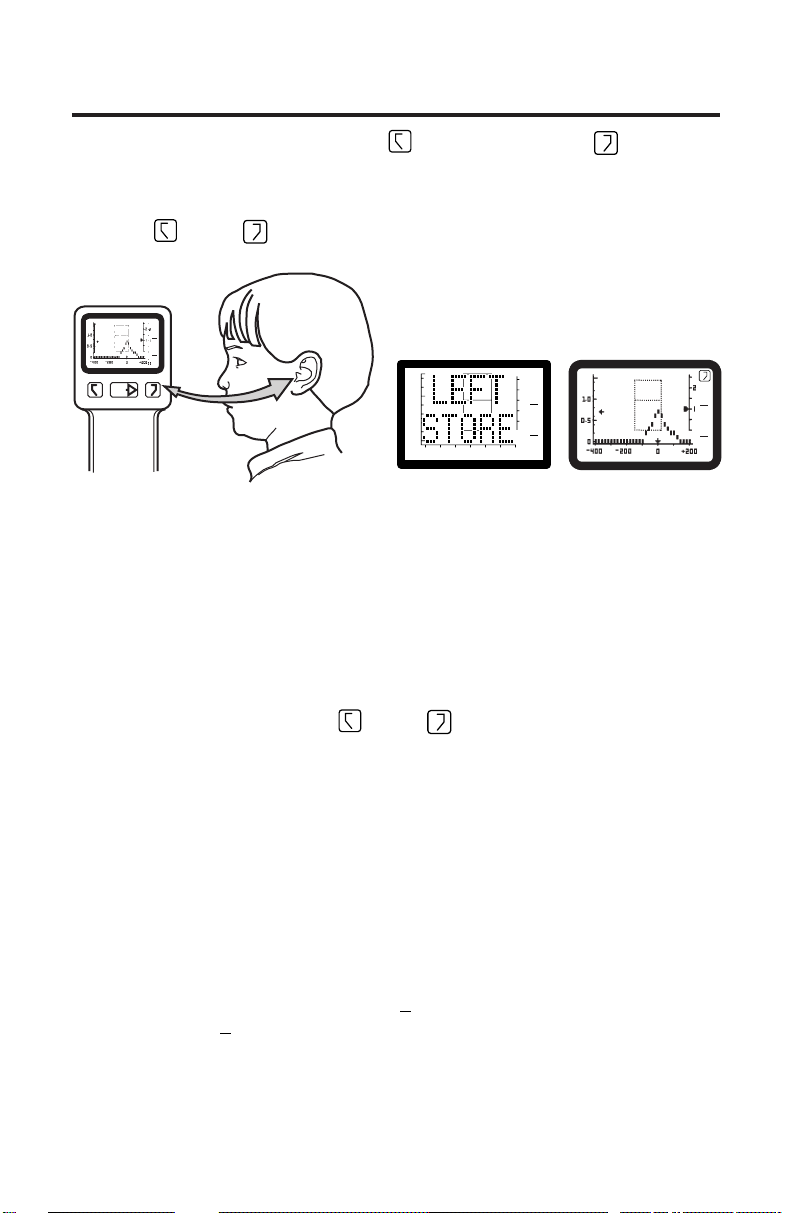
The memory buttons are labeled for the right ear and L for the left
R
ear. When test results are stored in memory, the RIGHT STORE or LEFT
STORE message (see Figure 7A) appears momentarily on the LCD.
Then the tympanogram which has been stored reappears along with the
R
right
or left L symbol (see Figure 7B) to indicate the contents of
that memory.
2
-400 -200 0 200
PRESSURE - daPa
RLTEST
GR
A
1
GR
C
+200 Vea - cc
2
1.0
0.5
Ya - mmho
0
-400 -200 0 200
PRESSURE - daPa
1
GR
A
GR
C
1.0
0.5
Ya - mmho
+200 Vea - cc
0
-400 -200 0 200
PRESSURE - daPa
1.0
0.5
Ya - mmho
0
Figure 7 Figure 7A Figure 7B
Displaying Memory Contents
Information stored in memory may be recalled at any time by depressing
the appropriate memory button.
Erasing Memory Contents
There are two ways to erase memory contents:
• When a test is stored, the previous test is automatically erased.
R
• Depressing either the right
three seconds erases that memory.
or left L memory button for more than
L
2
GR
A
1
GR
C
+200 Vea - cc
Understanding the Liquid Crystal Display
(LCD) and Its Messages
The following messages may be displayed on the LCD during MicroTymp2
Handle operation:
Gradient (Width) Measurements
When a tympanometric tracing is complete, the MicroTymp2 measures
the gradient or width of the tympanogram. If the gradient is abnormal, an
asterisk will appear on the LCD under
years of age), or
GR
for the child’s ear (10 years of age or younger). For more
C
information, see Appendix A, “Guidelines for Tympanometry”, and Appendix
B, “Guidelines for Screening”.
GR
for the adult’s ear (greater than 10
A
8
Page 13
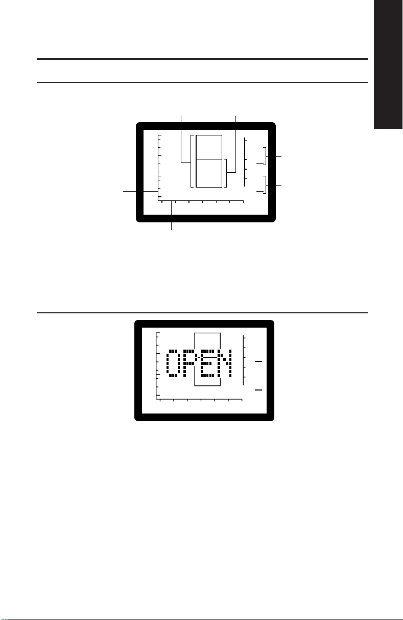
LIQUID CRYSTAL DISPLAY
Normal Static
Admittance and
TPP (Adults)
Normal Static
Admittance and
TPP (Children)
Completing a Test
MicroTymp
2
Admittance
Axis
1.0
0.5
Ya - mmho
0
-400 -200 0 200
PRESSURE - daPa
2
1
GR
GR
A
C
Gradient
(Width) Adult
Gradient
(Width) Child
+200 Vea - cc
Pressure
Axis
Figure 8
A sample of the Liquid Crystal Display is shown in Figure 8.
OPEN
2
1.0
0.5
Ya - mmho
0
-400 -200 0 200
PRESSURE - daPa
Figure 9
GR
1
GR
A
C
+200 Vea - cc
The test has not begun since a valid ear cavity has not been detected.
The ear canal volume exceeds 2.5 cc.
Possible causes:
• instrument is not in an ear
• probe tip is not completely sealed in an ear
• instrument is used on perforated tympanic membrane, an ear with
patent tympanostomy tubes, or an extremely large canal (> 2.5 cc).
9
Page 14
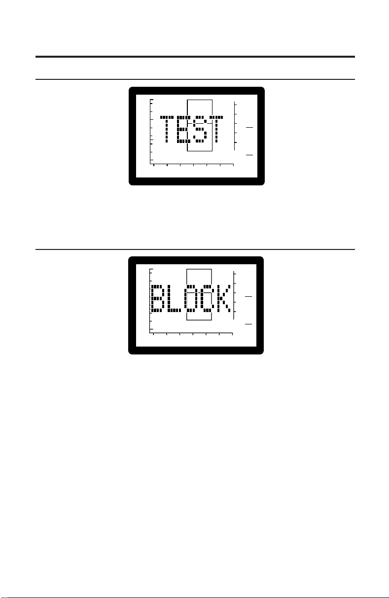
TEST
2
1.0
0.5
Ya - mmho
0
-400 -200 0 200
PRESSURE - daPa
GR
1
GR
A
C
+200 Vea - cc
Figure 10
The TEST message indicates that the test has started. Immediately following
this message, test data will begin to appear.
BLOCK
2
1.0
0.5
Ya - mmho
0
-400 -200 0 200
PRESSURE - daPa
Figure 11
GR
1
GR
A
C
+200 Vea - cc
The test cannot continue since the measured admittance is less than 0.2 mmho.
Possible causes:
• probe tip is lodged against canal wall
• ear canal occluded
• collapsed ear canal
• extremely small ear or tortuous canal
• probe tip is clogged with cerumen
Possible solutions:
• reposition the probe tip
• perform otoscopy to check for occlusion
• remove cerumen from probe tip
10
Page 15

LEAK
2
1.0
0.5
Ya - mmho
0
-400 -200 0 200
PRESSURE - daPa
Figure 12
The test cannot proceed since desired pressures within the ear have not
been achieved.
Possible causes:
• probe tip is not completely sealed in the ear canal
• excessive movement of patient or practitioner
• probe tip dislodged during a test
Possible solutions:
• reposition probe tip
• patient and practitioner must remain still
• use a different size probe tip
• increase pressure against the ear
GR
1
GR
A
C
+200 Vea - cc
Completing a Test
MicroTymp
2
If a leak condition occurs after -100 daPa pressure is reached, results will
remain on the display. If an identifiable peak is displayed, the test need not
be repeated. If no peak can be identified, repeat the test and try repositioning the tip, using a different size tip, or increasing the pressure against the
ear canal opening.
RIGHT STORE/LEFT STORE
1.0
0.5
Ya - mmho
0
-400 -200 0 200
PRESSURE - daPa
1
GR
GR
A
C
+200 Vea - cc
1.0
0.5
Ya - mmho
0
-400 -200 0 200
PRESSURE - daPa
2
Figure 13A Figure 13B
Test results have been stored in the designated memory location. Immediately following this message, the newly-stored tympanogram reappears
along with the right
R
or left L symbol. For instructions on storing and
erasing data, see page 7.
11
2
GR
1
GR
A
C
+200 Vea - cc
Page 16
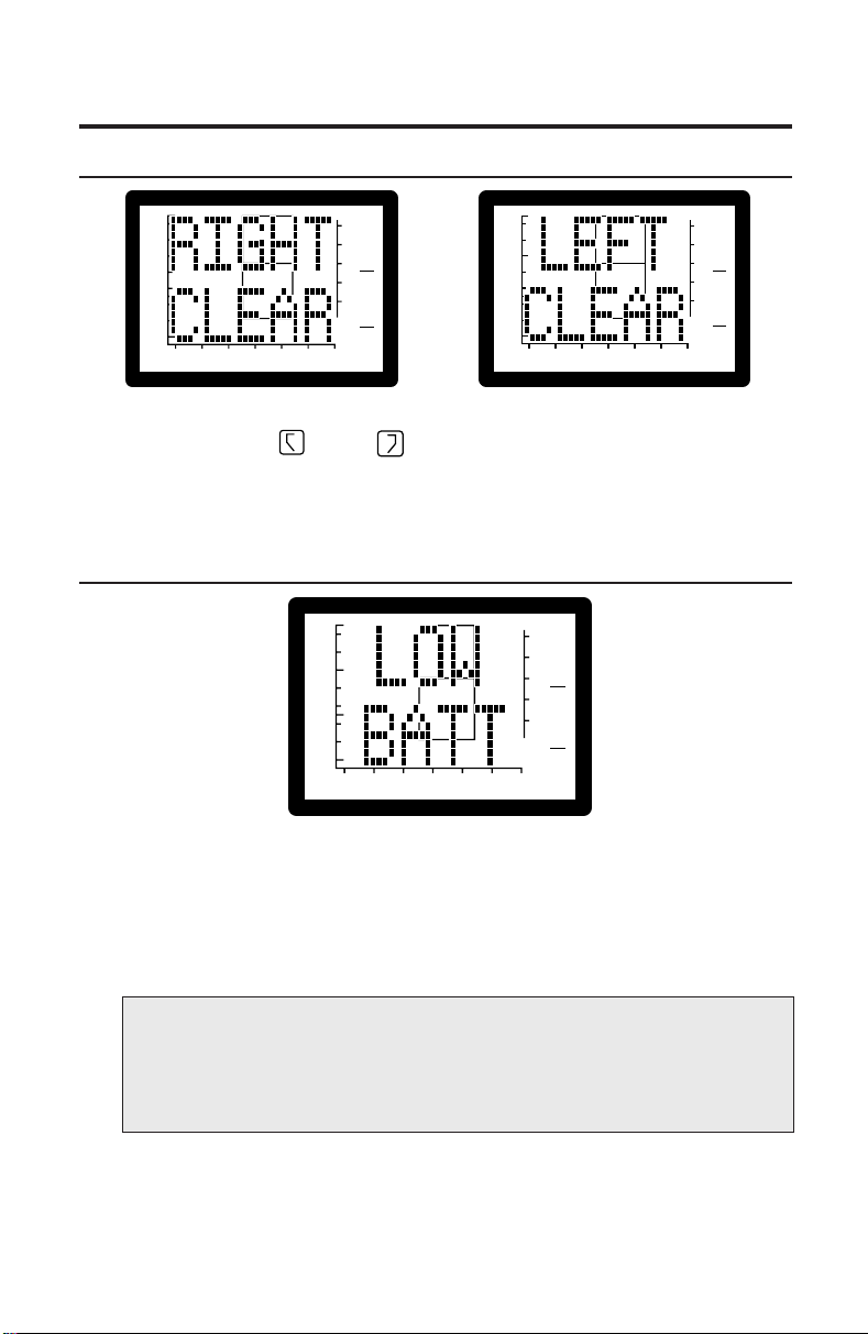
RIGHT CLEAR/LEFT CLEAR
1.0
0.5
Ya - mmho
0
-400 -200 0 200
PRESSURE - daPa
2
GR
1
GR
A
C
+200 Vea - cc
1.0
0.5
Ya - mmho
0
-400 -200 0 200
PRESSURE - daPa
2
GR
1
GR
A
C
+200 Vea - cc
Figure 14A Figure 14B
The designated right
R
or left L memory location contains no data.
Either no data has been stored, or previously stored data has been erased.
See page 7 for information on storing and erasing data.
LOW BATT(ery)
2
1.0
0.5
Ya - mmho
0
-400 -200 0 200
PRESSURE - daPa
Figure 15
The LOW BATT message indicates that the battery needs to be recharged.
All buttons are disabled to prevent inaccurate results due to inadequate
battery voltage. Normal operation may be restored by recharging the battery
or replacing the battery with a charged battery. Stored data is not lost when
the battery is removed.
GR
1
GR
A
C
+200 Vea - cc
NOTE: The battery must be removed if the MicroTymp2 Handle
is to be stored or placed anywhere other than in the powered
Printer/Charger for more than one month. Failure to do this can
result in damage to the MicroTym p2 Handle.
See Appendix C, “Maintaining the MicroTymp2 Equipment,” for instructions
on removing and recharging the battery.
12
Page 17
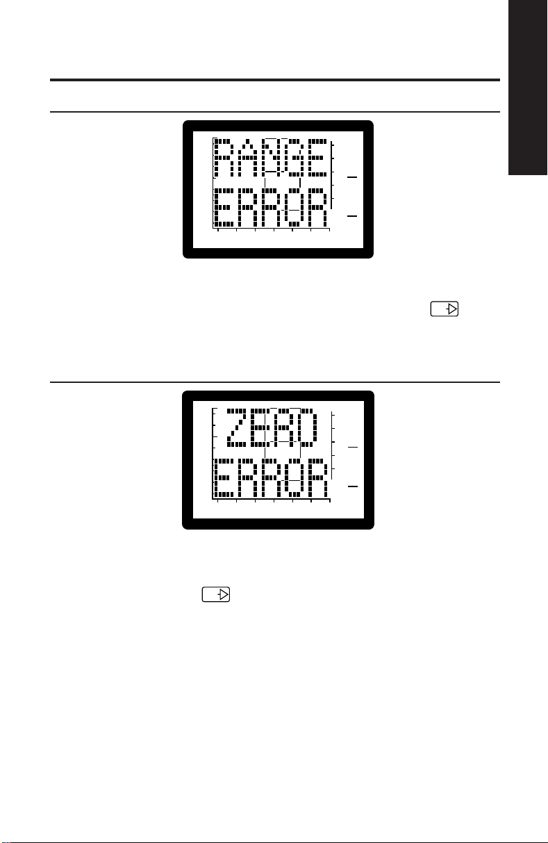
RANGE ERROR
1.0
0.5
Ya - mmho
0
-400 -200 0 200
PRESSURE - daPa
Figure 16
2
GR
1
GR
A
C
Completing a Test
MicroTymp
2
+200 Vea - cc
The RANGE ERROR message indicates that a large pressure change
occurred during a test. If this message appears, press the TEST
TEST
button and start the test again.
ZERO ERROR
2
1.0
0.5
Ya - mmho
0
-400 -200 0 200
PRESSURE - daPa
Figure 17
The ZERO ERROR message indicates that a large pressure change occurred
during automatic pressure compensation at the start of a test. If this message
appears, press the TEST
TEST
button and start the test again.
GR
1
GR
A
C
+200 Vea - cc
13
Page 18
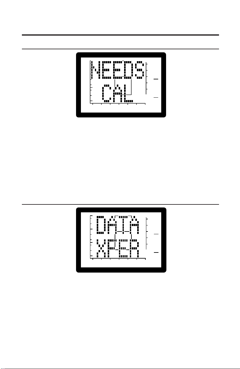
NEEDS CAL(ibration)
2
1.0
0.5
Ya - mmho
0
-400 -200 0 200
PRESSURE - daPa
GR
1
GR
C
A
+200 Vea - cc
Figure 18
Something has caused the MicroTymp2 to fail an internal calibration test.
All MicroTymp2 buttons have been disabled because the instrument needs
to be returned to a Welch Allyn service location for calibration. Any results
already stored in the handle may be printed.
Annual recalibration is recommended to insure instrument accuracy. See
Appendix E, “Service and Warranty Information,” for details on service
locations and recalibration.
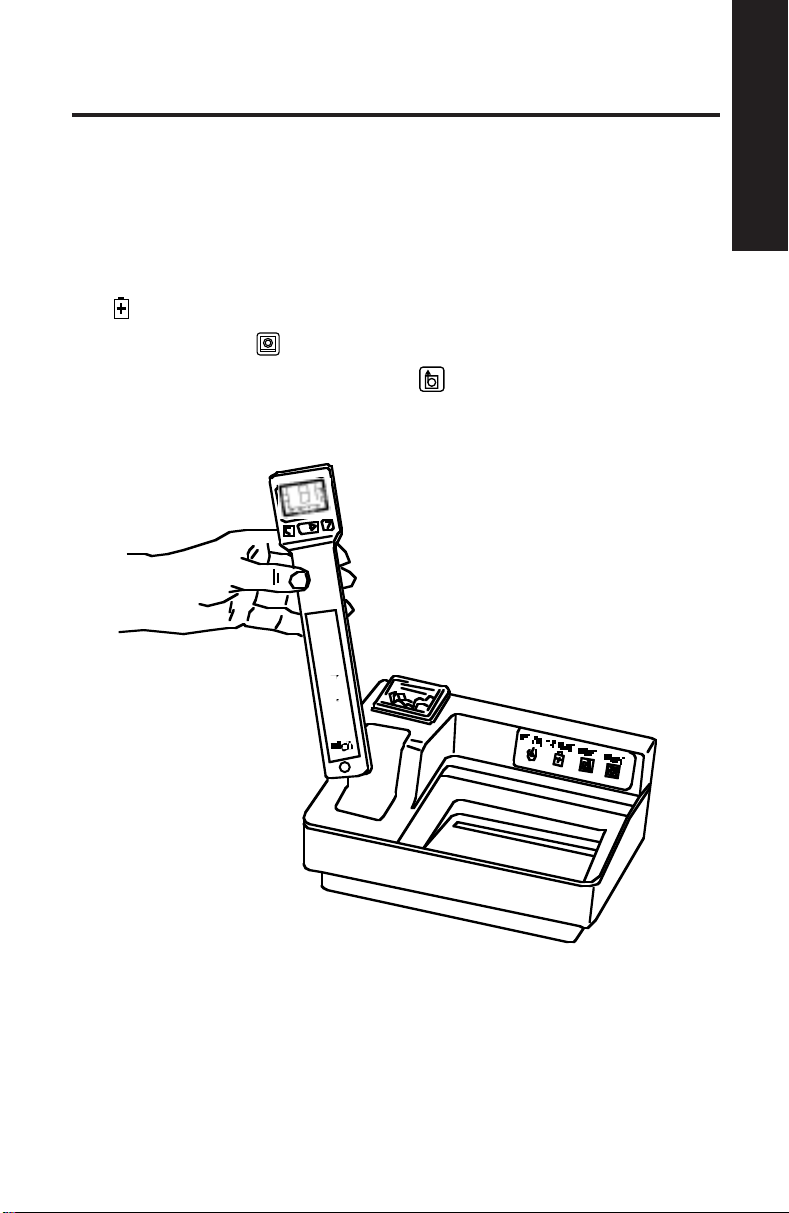
DATA XFER(transfer)
2
1.0
0.5
Ya - mmho
0
-400 -200 0 200
PRESSURE - daPa
GR
A
1
GR
C
+200 Vea - cc
Figure 19
The data stored in the MicroTymp2 Handle is being transferred to the
Printer/Charger.
14
Page 19
Completing a Test
MicroTymp
Printing Memory Contents
Follow the steps listed below to print tympanometric data stored in the
MicroTymp2 Handle:
1. Place the MicroTymp2 Handle in the well with the Liquid Crystal Display
(LCD) and buttons facing you. See Figure 20.
When the MicroTymp2 is properly seated in the well, the green CHARGE
indicator illuminates.
2. Press the PRINT
3. To feed extra paper, press the FEED
feed as long as the button is depressed.
button.
button. Paper continues to
2
Figure 20
15
Page 20

4. To remove the printout, pull the paper forward and to the left or right to
tear it along the cutting edge.
5. To obtain an additional copy of the test results, leave the Handle in the
well and press the PRINT
Handle from the well causes the data to be removed from the Printer/
Charger memory.
NOTE:
• The Printer/Charger has been pre-set at Welch Allyn to print
a complete printout as illustrated in Figure 21 on page 17,
and to print in manual mode. To change formats or print in
automatic mode, follow the instructions on page 20.
• If only one ear has been tested, the memory for the other
ear should be erased (see page 8) so as not to confound
current data with data from a previous patient.
• If only one memory location has data, only one result is printed.
• Do not use transparent adhesive tape on the printed portions
of a printout, as those portions will then fade.
button again. Removing the MicroTymp2
MicroTymp2 Printout Formats
Description of Formats
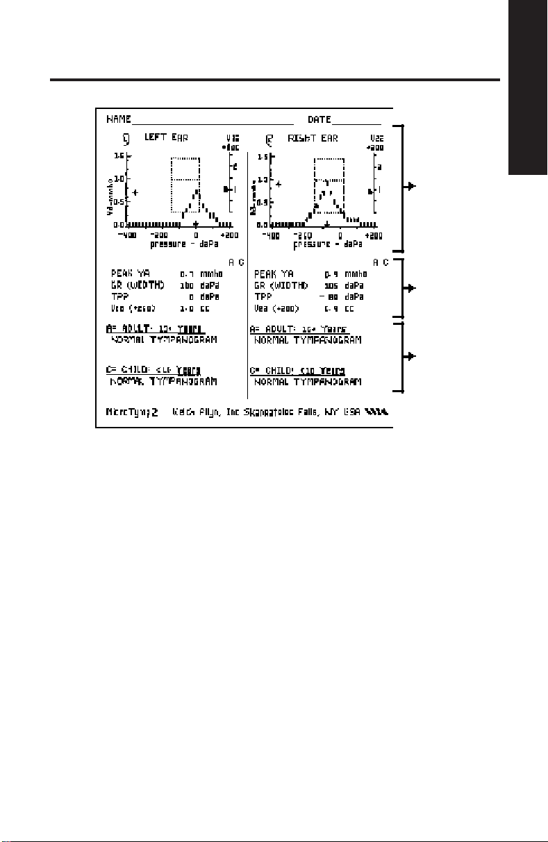
A complete tympanometric printout is shown in Figure 21. The printout is
divided into three sections: tympanogram, data, and interpretive messages.
Following is a detailed account of the information presented in each of these
sections. For instructions on changing the format of the printout, see page 20.
16
Page 21
Tympanogram
Data
(Optional)
Interpretive
Message
(Optional)
Completing a Test
MicroTymp
2
Figure 21
Tympanogram Section of Printout
The tympanogram is a graph which records the admittance of the ear as
a function of air pressure.
Data Section of Printout
The data section displays numeric values for the four key characteristics
of the tympanogram:
• Peak Ya — the compensated static acoustic admittance (height) of
the peak, measured in acoustic millimhos (mmho).
• Gradient (GR) — the width of the tympanogram; the distance across
the tympanogram measured at a height 50% down from the peak,
measured in decapascals (daPa).
• Tympanic Peak Pressure (TPP) — where the tympanometric peak
occurred on the pressure axis, measured in decapascals (daPa).
• Volume of the Ear Canal (Vea) — acoustically-determined ear canal
volume, measured in cubic centimeters (cc) at +200 daPa.
17
Page 22

If the numeric values are greater or less than the 90th percentile of the
normative data for a child or an adult, an asterisk appears under the C(hild)
or A(dult) column. The normative data are listed in Table 1 below.
For some tympanometric results, no data will be printed. These occasions are:
• Peak Ya is greater than 1.5 mmhos. The message “High Peak Ya” will
appear at the top of the tympanogram.
• Peak Ya less than 0.3 mmhos.
• Peak Ya which is incomplete; for example, a negative pressure
tympanogram which is so far negative that the peak has not been
reached and data are incomplete.
• Tympanogram has too much artifact. Artifact is generally caused by
movement of the subject or the instrument.
Table 1 — Normative Tympanometric Data
Tympanometric Child’s Ear Adult’s Ear
Measurement (Under Age 10) (Over Age 10)
90% Range 90% Range
Peak Ya 0.2 to 0.9 mmho 0.3 to 1.4 mmho
Gradient (GR)
(Tympanometric Width) 60 to 150 daPa 50 to 110 daPa
Tympanometric
Peak Pressure (TPP) -139 to +11 daPa -83 to 0 daPa
Equivalent Ear Canal
Volume (Vea) 0.4 to 1.0 cc 0.6 to 1.5 cc
NOTE: For purposes of tympanometric norms, an adult is
defined as a person 10 years of age or older, and a child as
under age 10.
Normative data are taken from a study by Margolis and Heller
(1987), and from the “Guidelines for Screening for Hearing
Impairments and Middle Ear Disorders” ASHA (1990).
18
Page 23

Interpretive Messages Section of Printout
The interpretive messages section of the printout provides an interpretive,
verbal description of the tympanometric result.
The computer in the Printer/Charger examines the data for clinically-significant deviations from the normal values. For example, a tympanogram which
is too wide may be indicative of a developing or resolving otitis media; the
message reads “Tympanogram Is W ide”.
The hierarchy of messages displayed is as follows:
Noisy Tympanogram (too much artifact near the peak)
Low Peak Height, Small Ear Volume
Low Peak Height, Normal Ear Volume
Low Peak Height, Large Ear Volume
Tympanogram Is W ide
Negative Tympanometric Peak Pressure
Positive Tympanometric Peak Pressure
High Peak Height
Normal Tympanogram
The computer scans the list of messages and prints the first message that
applies. The hierarchy is arranged so that the most clinically-important
message is displayed first.
Completing a Test
MicroTymp
2
FOR THOSE USING THE ORIGINAL MICROTYMP HANDLE
NOTE: The original MicroTymp Handle functions identically
to the MicroTymp2 Handle with respect to printing. However,
since the original MicroTymp’s range is from +200 daPa to -300
daPa, no data points will print from -300 daPa to -400 daPa.
The Child Peak Ya limit on the original MicroTymp Handle is
0.2 to 0.8 mmho.
19
Page 24

Selecting Printout Formats
The four switches used to select the printout format and printer mode of
operation are located on the bottom of the Printer/Charger. See Figure 22.
NOTE: Switch #4 is used during manufacturing only. If Switch
#4 is ON, the Printer/Charger will not operate normally.
Changing from Manual to Automatic Printout
Use Switch #1 to change from manual to automatic printout.
Use a pointed object to depress appropriate ON or OFF portion of the switch.
1234
TYMPANOGRAM
AUTO
PRINT
ON
OFF
MANUAL
PRINT
NO
MESSAGES
MESSAGES2TYMPANOGRAM
1
ONLY
AND DATA
3
LEAVE
OFF
4
1234
OFF
OFF
Figure 22
Automatic vs. Manual Printout (Switch #1)
Auto Print Depress the ON portion of the switch to select this
1234
option. This causes the printout to begin automatically
once the MicroTymp Handle is placed in the well, and
data transfer is complete.
OFF
20
Page 25

Manual Print Depress the OFF portion of the switch to select this
1234
OFF
option. This causes the printout to begin only when
the PRINT
button is depressed.
NOTE: In the manual mode, a beep will occur as a reminder
that data has been transmitted; however, it is not necessary
to wait for the beep before pressing the PRINT
button.
Changing Printout Format
Use Switches #2 and #3, located on the bottom of the Printer/Charger, to
change printout format. Printout options are shown in Figure 23.
Use a pointed object to depress appropriate ON or OFF portion of the switch.
Tympanogram
Only (Switch 3)
1234
▲
Completing a Test
MicroTymp
2
Figure 23
21
OFF
Tympanogram
and Data (Switch 3)
1234
▲
OFF
Messages
▲
(Switch 2)
1234
OFF
No messages
(Switch 2)
1234
OFF
Page 26
Printing Interpretive Messages (Switch #2)
No messages Depress the ON portion of the switch to select this
1234
option. This causes messages which interpret the
tympanogram to not be included on the printout.
Refer to Description of Formats on page 16 for
OFF
more information on these messages.
Messages Depress the OFF portion of the switch to select this
1234
option. This causes the messages which interpret the
tympanograms to be included on the printout.
OFF
Printing Tympanogram Only or Tympanogram and Data (Switch #3)
Tympanogram Depress the ON portion of the switch to select this
Only option. Only the tympanogram and the GR (Width)
1234
OFF
numeric value will print.
Tympanogram Depress the OFF portion of the switch to select this
and Data option. Both the tympanogram and its corresponding
1234
OFF
numeric data will print.
Manufacturing Switch (Switch #4)
1234
This switch is used during manufacturing only. Leave
this switch in the OFF position. The Printer/Charger
will not operate normally if this switch is on.
OFF
22
Page 27

Completing a Test
MicroTymp
Printer Function Messages
If tympanometric results are not printed, a message will appear describing
the reason. These messages are listed in Table 2.
Table 2 – Printer Function Messages
Printer Function Possible Cause Possible Solution
Message
No Data The MicroTymp Handle Seat the handle in
Reinsert Handle is not located in the well. the well.
The MicroTymp Handle Insure that the handle
is not seated properly is fully seated in the well
in the well. with the Liquid Crystal
Display (LCD) and
buttons facing you.
The MicroTymp Handle Verify battery is in
has a discharged or place, and charged
missing battery. (LOW BATT message
does not appear).
The MicroTymp Handle Call your nearest
is not functioning Welch Allyn service
properly. location, distributor,
or factory representative.
R
No Data Both right
Nothing in Memory left
L
memory loca- being stored correctly.
tions in the MicroTymp See page 7.
Handle are empty.
Computer Interface Switch #4 on Turn switch #4 OFF.
Switch 4 is Set on Printer/Charger is ON. See page 22.
Bottom of Printer
and Insure that data is
2
23
Page 28

Printer Service Codes
When the Printer/Charger is plugged into an electrical outlet, the green
POWER
the printer is ready for use.
indicator illuminates and the instrument beeps to indicate that
If a problem exists, the green POWER
flashes correspond to the specific problems listed in Table 3.
Table 3 – Printer/Charger Flashing Indicators
Number of Problem Solution
Flashes
One Printer/Charger is out Replace paper. See
of paper. page C-48 for instructions.
Two Paper lever is in wrong Retur n paper lever to its
(forward) position. original, correct position.
Three System failure within Verify that switch #4 is in
or More Printer/Charger. the OFF position. Unplug
NOTE: If the green POWER indicator is not illuminated,
verify connection to live power source. If the problem persists,
return the Printer/Charger to the nearest Welch Allyn service
location.
indicator flashes. The number of
See page C-49 for instructions.
the Printer/Charger. Wait one
minute, then re-apply power
to the instrument. If Printer/
Charger does not return to
normal operation, return it
to the nearest Welch Allyn
service location.
24
Page 29

Appendix A
Guide to Tympanometry
Aural acoustic immittance measurements have become an integral component
of audiologic and otologic evaluation. One class of aural acoustic immittance
measurement, tympanometry, has become routine in the assessment of ear
disease. Since the original report of Terkildsen and Thomsen (1959), tympanometry has been used widely by physicians and audiologists as a research tool
for studying the effects of ear disease on middle ear function and as a clinical
test for detecting medically-significant pathology. Recent technological advances
have paved the way for MicroTymp2, a low-cost, portable, precision instrument
that can be of significant value for determining the need for medical referral,
for diagnosis of ear disease, and for monitoring the course of medical/
surgical intervention.
The Welch Allyn MicroTymp2 is a single-component, aural acoustic admittance meter that records a tympanogram with a 226-Hz probe tone.
Basic Principles of Tympanometry
Acoustic admittance is the ease with which acoustic energy is transferred
from one system to another. If the air in the ear canal is easily set into vibration,
the admittance is high. If the air is difficult to set into vibration, the admittance
of the system is low. The ease or difficulty of setting the air in the ear canal
into vibration is determined by the volume of air and the admittance of the
middle ear. Tympanometry provides a method of evaluating the physical
characteristics of the ear canal/middle ear system by measuring the admittance of the air trapped in the ear canal.
Appendix A
Tympanometry is the measurement of acoustic admittance as a function
of ear canal air pressure. The resulting graph is a tympanogram. Because
ear canal air pressure changes the admittance of the middle ear, the admittance of the air in the ear canal changes when the ear is pressurized. Positive
or negative pressure, introduced into the sealed ear canal, decreases the
admittance of the air in the ear canal by stiffening the eardrum. The effect
of air pressure on the acoustic admittance measured in the ear canal is systematically altered by ear disease. Tympanometry is a sensitive indicator of
the effects of ear disease on the acoustical and mechanical function of the
middle ear.
A-25
Page 30

Tympanogram Characteristics
Figure 24 illustrates a MicroTymp2 tympanogram. A description of the key
characteristics of the tympanogram follows.
1
2
3
Figure 24
4
1
Static Admittance (Peak Ya) is a measure of the height of the tym-
panometric peak. Given appropriate normative values, static admittance
is a useful indicator of middle ear disease.
2
Tympanometric Gradient (GR), or tympanometric width, is a measure
of the width of the tympanometric peak. Defined as the width of the tympanogram (in decapascals) at 50% of peak eardrum admittance, tympanometric width is a good indicator of the presence of middle ear effusion.
3
Tympanometric Peak Pressure (TPP) is the position of the tympano-
metric peak on the pressure axis. TPP is an imprecise measure of the
middle ear pressure. By itself, TPP is not an accurate indicator of middle
ear disease.
4
Equivalent Ear Canal Volume (+200 Vea) is the admittance value
determined with an ear canal air pressure of +200 daPa (decapascals).
A flat tympanogram with an abnormally-high equivalent ear canal volume
suggests the presence of a tympanic membrane perforation or a patent
tympanostomy tube.
A-26
Page 31

How the MicroTymp2 Instrument Works
A block diagram of a Welch Allyn MicroTymp2 is illustrated in Figure 25.
Sound
Out
Sound
In
Tip
Pressure
Transducer
Airflow
Pump
Microcomputers
Liquid Crystal
Display (LCD)
Loudspeaker
Microphone
Figure 25
A 226-Hz probe tone is introduced into the sealed ear canal by a miniature
loudspeaker. A miniature microphone records and monitors the sound
pressure produced in the ear canal.
The sound level is maintained at a constant 85 dB SPL (Sound Pressure
Level) throughout the test by a microcomputer. When the amount of sound
absorbed by the middle ear increases, the speaker is driven harder by
increasing the drive voltage to maintain the constant SPL. The voltage
required to maintain the probe tone at 85 dB SPL is proportional to the
acoustic admittance of the ear.
Appendix A
Air pressure in the ear canal is changed with a miniature pump. The pressure
transducer monitors air pressure, feeding this information to another microcomputer so that it can control the rate of pressure change (sweep rate).
As pressure in the ear canal is changed throughout a test, a microcomputer
computes acoustic admittance and plots admittance as a function of pressure
on the liquid crystal display.
A-27
Page 32

Normative Values for the MicroTymp2
The normative values listed in Table 4 are taken from a study by Margolis
and Heller (1987), and from the “Guidelines for Screening for Hearing
Impairments and Middle Ear Disorders” (1990).
Table 4 — Normative Tympanometric Values
Tympanometric Child’s Ear Adult’s Ear
Measurement (Under Age 10) (Age 10 & Over )
90% Range 90% Range
Peak Ya 0.2 to 0.9 mmho 0.3 to 1.4 mmho
Gradient (GR)
(Tympanometric Width) 60 to 150 daPa 50 to 110 daPa
Tympanometric
Peak Pressure (TPP) -139 to +11 daPa -83 to 0 daPa
Equivalent Ear Canal
Volume (Vea) 0.4 to 1.0 cc 0.6 to 1.5 cc
NOTE: For purposes of tympanometric norms, an adult is
defined as a person 10 years of age or older, and a child as
under age 10.
As the altitude above sea level increases, the admittance of a given volume
of air also increases. Therefore, equivalent ear canal volume (+200 Vea)
overestimates actual ear canal volume as noted in Table 5. To estimate
ear canal volume, subtract the appropriate value in Table 5 from the
MicroTymp 2 Vea Reading. Altitude can also affect MicroTest Cavity results.
Refer to Appendix D, “Functional Checks of the MicroTymp2 Handle and
Printer/Charger.”
Table 5 — Altitude Adjustments for Vea Readings
Altitude Adjustment Adjustment Adjustment Adjustment
for 0.5 cc for 1.0 cc for 1.5 cc for 2.0 cc
1280 ft 0.0 cc 0.0 cc 0.0 cc 0.1 cc
(390 m)
2530 ft 0.0 cc 0.1 cc 0.1 cc 0.2 cc
(770 m)
3220 ft 0.0 cc 0.1 cc 0.2 cc 0.3 cc
(980 m)
4757 ft 0.1 cc 0.2 cc 0.3 cc 0.4 cc
(1450 m)
A-28
Page 33

Interpreting Tympanogram Results
Otitis Media with Effusion
• Produces low static admittance
(low peak height) tympanogram
• Tympanogram is also typical of
tympanosclerosis, cholesteatoma,
and middle ear tumor
Oncoming or Resolving Otitis Media
with Effusion
• Produces normal peak height, but
tympanogram which is too wide
• Tympanogram is also typical of
tympanosclerosis
Normal Middle Ear
• Produces tympanogram within normal
limits relative to height and width
Appendix A
Tympanic Membrane Abnormalities or
Ossicular Disruption
• Produces high static admittance
(high peak height) tympanogram
Negative Middle Ear Pressure
• Produces negative Tympanometric
Peak Pressure (TPP) tympanogram
• Usually not associated with effusion
when Peak Ya is normal
• Also associated with eustachian tube
dysfunction, cold, or allergies
A-29
Page 34

Positive Middle Ear Pressure
• Produces positive Tympanometric
Peak Pressure
• Indicative of acute otitis media, if peak
is extremely positive
Tympanogram with Too Much Artifact
• Caused by patient or practitioner
movement
• Requires repeating measurement
Ear Canal Occlusion
• Can produce flat tympanogram with
ear canal volume lower than expected
• May also produce BLOCK message
• Requires repeating measurement
Patent Tympanostomy Tube or
Perforated Tympanic Membrane
• Can produce flat tympanogram with
ear canal volume higher than expected
• May also produce OPEN message
A-30
Page 35

Obtaining a Valid Tympanogram
Tympanometric results, although accurate and objective, do require careful
interpretation in conjunction with the patient’s overall clinical condition.
In addition, there are conditions which can cause artifact such that a
tympanogram is uninterpretable, or which artificially flatten the tympanogram.
These conditions are described in more detail below.
If too much artifact is noted, or if a flat tympanogram is considered suspect,
it is recommended that the tympanometric measurement be repeated.
Indeed, it maybe good clinical practice to repeat all clinical measurements
whenever possible.
Tympanometry in Young Infants
Research from the 1980s suggests that tympanometry should not be performed on infants aged six months or younger. More recent research suggests that it is appropriate to use 226 Hz tympanometry (e.g., MicroTymp2)
on infants as young as four months of age (Holte, 1990 and 1991).
Conditions Which Cause Too Much Artifact
Artifact is generally caused by either patient or practitioner movement.
See Figure 26. During the brief seconds when tympanometric measurements are obtained, it is important that the practitioner’s hand is steady,
and that the patient does not vocalize, talk, chew gum, yawn, cry, or make
any other similar movements. While this can be difficult with very young
children, it is now more achievable than ever with the tremendous speed
of MicroTymp2 tympanometry.
Appendix A
Figure 26 – Too Much Artifact
A-31
Page 36

Conditions Which Artificially Flatten the Tympanogram
In order to measure the mechanical properties of the middle ear, a tympanometric device must be capable of changing the pressure differential across
the eardrum. Any occlusion of the ear canal, such as impacted cerumen,
foreign body, tumor, stenosis, atresia, or a pocket created by the incorrect
placement of the probe, can prevent this pressure differential from happening
and can artificially flatten the tympanogram.
The result is that the volume of air in front of the probe will be very small.
The MicroTymp2 Handle will display the occurrence of this condition with
the BLOCK message if the volume is less than 0.2 cc. However it is possible
to obtain a flat tympanogram with a smaller than expected ear canal volume
(less than 0.4 cc for children or less than 0.6 cc for adults), as shown in Figure 27.
Figure 27 – Ear Canal Occlusion
A-32
Page 37

Patent Tympanostomy Tube or Perforated Tympanic Membrane
In the case of a tympanic membrane perforation or a patent tympanostomy
tube, the air pressure produced by the MicroTymp2 Handle escapes through
the perforation or tube so that a pressure differential across the eardrum
does not occur. Because the air pressure changes have no effect on the
tension of the eardrum, the tympanogram is flat with an unusually high
equivalent ear canal volume. If the volume exceeds 2.5 cc, the MicroTymp2
Handle will not record a tympanogram at all, and the OPEN message will
appear. See Figure 28.
2
1.0
0.5
Ya - mmho
0
-400 -200 0 200
PRESSURE - daPa
GR
A
1
GR
C
Flat Tympanogram Persistent OPEN
with too High Volume Message (can’t seal ear)
Figure 28
Appendix A
+200 Vea - cc
The Normal Ear
An example of a tympanogram from a normal ear is depicted in Figure 29.
Figure 29
A-33
Page 38

Low-Admittance Pathologies: Otitis Media with
Effusion, Middle Ear Tumor, Ossicular Fixation,
Tympanosclerosis
Low static admittance of the middle ear is produced by space-occupying
lesions in various ways. A lesion that displaces air in the middle ear space
causes low admittance by reducing the middle ear volume. The lesion also
may interfere with the vibration of the ossicular chain, contributing to the low
admittance. If the lesion is in contact with the eardrum, low admittance
results from interference with eardrum vibration.
Otitis Media with Effusion (OME)
Tympanometric characteristics of patients with OME typically include one or
more of the conditions illustrated in Figure 30. In advanced cases, OME
results in flat tympanograms (low static admittance). In intermediate stages
of OME, the peak height may be normal, but the gradient may be too wide.
Low Peak Ya Tympanogram Too Wide
Figure 30
A-34
Page 39

Middle Ear Tumor
A wide variety of neoplastic processes exist that invade the middle ear. The
most common is the keratoma (cholesteatoma), a collection of keratinizing
squamous epithelium that frequently originates from Shrapnel’s membrane
(pars flaccida) of the tympanic membrane or the ear canal wall and invades
the middle ear space. Other middle ear tumors include the cholesterol
granuloma, glomus tumor, and squamous cell carcinoma (Goodhill, 1979).
These pathologies generally result in a flat tympanogram.
Lateral Ossicular Fixation
Lateral ossicular fixation may result from tympanosclerosis, a complication
of chronic otitis media that may involve the eardrum, malleus, incus, and/or
stapes. In general, the more lateral the fixation, the more effect the condition
has on the tympanogram. Lateral fixations typically cause low static admittance and wide tympanometric widths.
Otosclerosis
Because the otosclerotic lesion is more medial than lateral ossicular
fixation, the tympanogram is less affected. The tympanometric shape is
often indistinguishable from normal, although the static admittance may
be slightly low and the tympanometric gradient (width) may be narrower
than the normal tympanogram.
Appendix A
A-35
Page 40

Tympanic Membrane Abnormalities
“Floppy” Tympanic Membrane
The tympanic membrane is normally a stiff, conically-shaped structure that
derives its stiff characteristic from the lamina propria, a layer of connective
tissue that is situated between the outer layer of squamous epithelium (skin)
and the inner layer of mucous membrane. When the eardrum heals after a
relatively large perforation, the lamina propria may be absent or thin in the
region of the scar. This neomembrane can be set into vibration with greater
ease than the normally-stiff tympanic membrane. The result is a high static
admittance. See Figure 31. Although the tympanogram is abnormal, this condition rarely affects hearing sensitivity or requires further medical treatment.
Ossicular Disruption
Disruption of the ossicular chain can range from partial interruption to complete
absence of the ossicles. These conditions result from the erosive effects of
chronic infection, trauma, and congenital defect. Ossicular disruption is
usually associated with a substantial conductive hearing loss. Because the
ossicles normally “load” the eardrum, contributing to its tension, the eardrum
in an ear with ossicular disruption can be more easily set into vibration than
the normal eardrum, resulting in high static admittance. See Figure 31.
Figure 31 – High Static Admittance
NOTE: When peak admittance exceeds 1.5 mmho, data
points will be plotted at baseline (0.0 mmho). See Figure 31.
A-36
Page 41

Conditions Which Cause Negative Middle Ear Pressure
Figure 32
Negative pressure within the middle ear space will produce a tympanogram
with a negative tympanometric peak. Some degree of negative pressure is
normal (see normal TPP values listed in Table 1 on page 18). Negative middle
ear pressure often accompanies a cold or allergies, or can be a result of
eustachian tube dysfunction. Negative middle ear pressure is not usually
associated with effusion when peak Ya is normal.
Conditions Which Cause Positive Middle Ear Pressure
Appendix A
Figure 33
Positive pressure tympanograms reflect positive pressure in the middle ear
space. A positive Tympanometric Peak Pressure (TPP) can be indicative of
acute otitis media, but only if the tympanometric peak is extremely positive.
A-37
Page 42

A-38
Page 43

Appendix B
Guidelines for Screening for Hearing
Impairments and Middle Ear Disorders
In a non-medical setting, tympanometry can be useful in determining the
need for a medical referral. However, abnormal tympanometric results occur
not only in patients with ear disease that requires medical attention, but also
in subjects with transient conditions that resolve without medical intervention
and in ears that have residual effects of previously-controlled disease. Consequently, it is unwise to base the decision of a medical referral on tympanometric
results alone. Screening protocols that have based medical referrals on tympanometric results alone have resulted in an excessively high over-referral
rate (Margolis and Heller, 1987).
Portions of the recommended screening protocol, published by the American
Speech-Language-Hearing Association (ASHA) in 1990, for determining the
need for medical referral are reproduced on pages B-40 to B-42. The guidelines are represented in a flow chart in Figure 34.
Appendix B
B-39
Page 44

1
/w
Ear Pain,
Discharge?
B-40
Page 45

Recommended Screening Protocol
The recommended screening protocol is based on a four-part procedure
consisting of case history, visual inspection, pure-tone audiometry, and
tympanometry. These guidelines can be used for all ages, however, they are
designed specifically for children and young adults (through age 40). Referral
criteria are presented in Table 6 on page B-42. These criteria may require
alteration for various clinical settings and populations.
The protocol is presented in flow chart format in Figure 34. The flow chart
is a representation of the logic used to determine the need for referral. It
does not represent the order in which test procedures are administered.
With the exception that visual inspection should precede tympanometry,
the order of test procedures is unimportant. The screening protocols described must be supervised by a clinical audiologist. Each test component,
indicated by a numbered box in Figure 34, is described below:
1
A recent, otologic history of otalgia or otorrhea is sufficient cause for
immediate medical referral.
2
Visual inspection of the ear may produce sufficient cause for medical
referral without the need for further testing. Referral criteria include:
structural defect of the ear, head, or neck; inflammation, blood, effusion,
excessive cerumen, tumors, or foreign body in the ear canal; or eardrum
appearance consistent with active middle-ear disease. When visual
inspection indicates the need for medical referral, tympanometry is not
necessary. When visual evidence of middle ear infection is present, or
when a pressure-equalization tube is in place, tympanometry should
not be performed unless requested by a physician.
Appendix B
34
Audiometric screening should be performed by the method described
in the ASHA Guidelines for Identification Audiometry (ASHA, 1985).
Those guidelines recommend screening with pure-tone stimuli presented
at 20 dB HL (re: ANSI S3.6-1989) with frequencies of 1000, 2000, and
4000 Hz. Failure to respond to any frequency constitutes failure of the
audiometric screen. In accordance with the Identification Audiometry
Guidelines, failure of the audiometric screen should be confirmed by
a rescreen, either on-site or by additional testing at a later date. If the
audiometric screen is failed on the second administration, a complete
audiologic evaluation should be performed.
56
Low static admittance (Peak Y [Ya]) associated with an abnormally-large
volume in front of the probe is evidence of a tympanic membrane perforation and warrants immediate referral. The presence of (Vec [Vea])
(estimated at 200 daPa) exceeding the 90% range listed in Table 6 on
page B-42, and in the presence of a flat tympanogram is evidence of a
large volume and should result in a medical referral.
B-41
Page 46

7
Low static admittance (Peak Y [Ya]) may or may not be associated with
significant middle ear disorders. In the absence of other positive findings,
a Peak Y (Ya) below the 90% range listed in Table 6 requires observa-
tion over an extended period before a medical referral is warranted.
Only after two successive abnormal findings over an interval of 4-6
weeks should medical referral be made.
8 9
An abnormally-wide tympanometric width (TW) may occur in the absence
of other findings in cases with otitis media. These cases may represent
transient secretory otitis media, which does not require medical referral.
Like static admittance, abnormal TW in the absence of other signs of
middle ear disorders requires a retest after 4-6 weeks, and only then
should a medical referral be based on this finding alone.
Audiologic or Medical Referral
Failure of the screen should result in an audiologic evaluation and medical
examination. The nature of the referral may depend upon the characteristics
of the screening program and the availability of services. For example, the
referral may be to a clinic that provides both audiologic and medical services.
Alternatively, an audiologic referral may precede the medical referral. If audiologic services are not available, an immediate medical referral should be
made upon failure of the screening protocol.
Table 6
Peak Y [Ya] Vec [Vea] TW
(mmho or cm3) (cm3) (daPa)
Mean 90% Mean 90% Mean 90%
Range Range Range
Children 0.5 0.2 to 0.9 0.7 0.4 to 1.0 100 60 to 150
Adults 0.8 0.3 to 1.4 1.1 0.6 to 1.5 80 50 to 110
B-42
Page 47

Appendix C
Maintaining the MicroTymp2 Equipment
The MicroTymp2 Battery
The MicroTymp2 rechargeable nickel-cadmium battery is intended for many
charge/discharge cycles and is warranted for two years. The warranty
expiration date is imprinted on the battery.
BATTERY REPLACEMENT: Replace with Welch Allyn model
!
#72900 battery only.
NOTE: This instrument contains components which are static
!
sensitive. Before touching any internal handle component, be
sure that you have discharged any static electricity by touching
a grounded metal object.
NOTE: Disassembly of the MicroTymp2 beyond the extent
!
described in this manual will void the warranty. Refer all
servicing to Welch Allyn or a Welch Allyn Authorized
Service Representative listed on page E-55.
Replace the battery by following these steps:
1. Allow the MicroTymp2 Handle to tur n off.
2. Unscrew the battery cover in a counterclockwise direction using the
#0 Phillips head screwdriver provided. See Figure 35. Save the screw.
Figure 35
C-43
Appendix C
Page 48

3. Remove the battery cover by lifting the bottom of the cover away from
the probe tip. See Figure 36.
USE ONLY SPECIFIED CHARGER
RECHARGEABLE BATTERY 2.4 VOLTS 600mAh
CATALOG NO. 72900
Figure 36
4. Push down on the positive (+) end of the battery. Battery will eject.
See Figure 37.
Figure 37
Battery will
eject
USE ONLY SPEC
RECHARGEABLE BA
CATALOG NO.
Apply
Pressure
C-44
Page 49

5. Insert the replacement battery by placing the positive (+) end of the
battery against the spring in the holder. Push the battery lightly to
compress the spring, and lower the battery into the compartment.
See Figure 38.
NOTE: Insert the battery only as shown. Failure to observe the
correct polarity will prevent the instrument from functioning.
USE ONLY SPECIFIED CHARGER
RECHARGEABLE BATTERY 2.4 VOLTS 600mAh
CATALOG NO. 72900
Figure 38
6. Replace the cover by inserting the tip end under the front cover, lowering
the opposite end, and replacing the screw.
7. Tighten screw in clockwise direction. To avoid stripping the screw
threads, do not tighten excessively.
C-45
Appendix C
Page 50

Recharging the Battery
To recharge the MicroTymp2 battery, place the MicroTymp2 Handle in the
Printer/Charger well with the LCD and buttons facing you. See Figure 39.
NOTE: Charge only with the MicroTymp2 Printer/Charger (#71170,
!
#71175) or special AudioScope Charging Stand (#71126).
The 2.4 V nickel-cadmium battery used in the MicroTymp2, when fully
charged, provides a full day of operation without the need for recharging —
yielding a minimum of 300 double ear tests. This makes the MicroTymp2
instrument optimal for mass screening or off-site situations where there
may not be a need to print, but there is a need for continuous operation.
The LOW BATT message will appear on the LCD when the battery voltage
is too low to provide reliable operation. All buttons are automatically disabled
when the battery is low to prevent inaccurate results due to inadequate
battery voltage. However, results which were previously stored may be
recalled or printed when the battery is recharged or replaced.
A fully drained battery should be recharged overnight (14-16 hours).
NOTE:
• The MicroTymp2 Handle may be charged indefinitely without damage to the battery.
• Slight heating of the MicroTymp Handle during charging
is normal.
• The battery must be removed if the MicroTymp2 Handle
is going to be stored or placed anywhere other than in the
powered Printer/Charger for more than one month. Failure
to do this can result in damage to the battery and to the
instrument.
• The battery will self-discharge gradually over a period of
approximately 60 days when stored at room temperature
(70˚F/21˚C); storage at higher temperatures accelerates the
discharge rate.
C-46
Page 51

Figure 39
Recycling the Battery
Recycling Nickel-Cadmium Batteries (North America Only)
Welch Allyn employs the services of an agency which can disassemble and
recycle all components of nickel-cadmium batteries so that nothing gets
placed in a landfill or incinerated. To recycle an expended Welch Allyn
rechargeable battery, please send to:
Welch Allyn Welch Allyn Canada
RECYCLE BATTERY RECYCLE BATTERY
4341 State Street Road 160 Matheson Blvd. East, Unit 2
Skaneateles Falls, NY 13153-0220 Mississauga, Ontario
CANADA L4Z 1V4
Nickel-Cadmium Battery.
Must be Recycled or
Disposed of Properly.
C-47
Appendix C
Page 52

Paper Replacement
The MicroTymp2 Printer/Charger signals the need for changing the paper in
one of two ways:
• A pink strip appears along the edge of the paper indicating the paper is
nearing the end of the roll.
• The POWER
no paper, and no printing can occur.
NOTE:
• Use only an appropriate heat-sensitive paper or the Printer/
Charger life may be shortened and the warranty voided.
• The paper is thermally activated, so it must be stored in a
cool, dark location to prevent exposure and degraded
performance.
• Because the paper is thermally activated, no printing will
appear on the paper if it is inserted backwards.
• Do not use transparent adhesive tape on printed portions
of the printout, as those portions will then fade.
To Replace the Paper
CAUTION: Disassembly of the Printer/Charger presents a
possible electrical-shock hazard. Refer all servicing to Welch
Allyn or a Welch Allyn authorized service representative, listed
on page E-55.
1. Remove the paper access cover by pulling up on the front edge. See
Figure 40.
indicator flashes in single pulses indicating that there is
Appendix C
Figure 40
C-48
Page 53

2. Depress the FEED button to advance any remaining paper through
the printer. Do not pull paper backwards through the printer. Remove
and discard old paper roll, saving the black spindle.
3. Pull the paper lever forward. See Figure 41.
Figure 41 Figure 42
4. Place the roll of paper behind the Printer/Charger for easier handling.
5. Insert the paper (from of the bottom of the roll) into the slot under the
pinch roller, making sure that the paper is centered. See Figure 42.
6. Return the paper lever to its original position, and press the FEED
button to advance several inches of paper beyond the pinch roller.
7. Tighten the paper on the paper roll, reinsert the black spindle through
the roll, and place the paper roll in the paper cradle.
8. Feed the paper through the slot in the paper access cover.
NOTE: Make sure that the paper is taut before replacing the
paper access cover. Loose paper can cause printer malfunction.
9. Replace the cover by sliding the back edge into place first and lowering
the front of the paper access cover.
C-49
Appendix C
Page 54

Cleaning, Disinfection and Sterilization
Cleaning the MicroTymp2 Handle
Do not sterilize the MicroTymp2 Handle. Clean the Handle by wiping it with
a dry cloth or a cloth that has been lightly dampened with 70% Isopropyl
alcohol. Make sure liquid does not seep into the instrument, especially
in the probe area. Inspect the probe opening and the three inside ports for
debris monthly. Dust, cerumen, or other material in the probe may affect the
accuracy and/or functioning of the instrument.
Printer/Charger Cleaning
Do not sterilize the MicroTymp2 Printer/Charger. Make sure liquid does not
seep into either the printer area or the charging well. Clean the Printer/Charger
by wiping it with a dry cloth or a cloth that has been lightly dampened with
70% Isopropyl alcohol.
Disinfection and Sterilization of the Probe Tips
The probe tips should be disinfected after each patient.
According to the Occupational Safety and Health Administration (OSHA), the
probe tips should be “cleaned and decontaminated...(if) contaminated with
blood or other potentially infectious materials.”
The probe tips may be sterilized as follows:
Ethylene Oxide: 130˚F (54˚C), 8 PSI (55 kPa), 4-hour cycle
Steam Autoclave: 270˚F (132˚C), 27 PSI (185 kPa), 6-minute cycle
The probe tips may be disinfected as follows:
Cidex™
Cidexplus™
70% Isopropyl alcohol
Betadine® (10% by volume)
Wescodyne® (10% by volume)
Metricide
Boiling water (30 minutes)
NOTE: Zephiran® Chloride (with or without anti-rust tablets)
is not recommended as a disinfection solution. Using Betadine,
Wescodyne, or boiling water may discolor probe tips; however,
performance is not affected.
If the probe tips are wiped while attached to the MicroTymp2,
point the probe tip down to prevent seepage of liquid into the
probe tip.
C-50
Page 55

Appendix D
Functional Checks of the MicroTymp2
Handle and Printer/Charger
Functional Checks of the MicroTymp2 Handle
A MicroTest Cavity is included with the MicroTymp2 Handle. The cavity
provides a functional test of the MicroTymp2 Handle to determine if it is
working properly. The 0.5 cc cavity is used to test the Low Range of ear
canal volume (Vea). The 2.0 cc cavity is used to test the High Range of the
ear canal volume (Vea).
Check the MicroTymp2 Handle with the MicroTest Cavity at least once a
month and whenever the operation of the MicroTymp2 Handle is questioned.
To use the MicroTest Cavity, follow the steps below.
1. Using any size probe tip, place the MicroTymp2 probe tip against the
0.5 cc cavity as if it were an ear. See Figure 43. Hold the handle and
MicroTest Cavity carefully to prevent movement. Depress the TEST
button and test the cavity as you would an ear (see page 6 for information on performing a test).
2
GR
A
1.0
1
GR
0.5
B
+200 Vea - cc
0.5cc
2.0cc
MicroTest
CAVITY
Ya - mmho
0
-200
-400
PRESSURE - DaPa
200
0
R
Test
TEST
Button
TEST
Figure 43
2. Store the information using either the right
R
or left L memory buttons.
3. Repeat Steps 1 and 2 using the 2.0 cc cavity. Store the information in
the opposite memory location used in Step 2.
4. Print the information using the Printer/Charger.
D-51
Appendix D
Page 56

5. A properly functioning instrument will produce a flat tympanogram and
an ear canal volume (Vea) which corresponds to the cavity tested. There
is an acceptable range for each cavity (see Table 7) both at sea level
and at different altitudes. An example is provided in Figure 44 below.
Note that all data points must fall within the two bottom rows of the graph.
2
GR
A
1.0
1
GR
0.5
B
+200 Vea - cc
0.5cc
2.0cc
MicroTest
CAVITY
Ya - mmho
0
-200
-400
PRESSURE - DaPa
R
200
0
Tympanogram from 0.5 cc cavity
Figure 44
Table 7 – Expected Vea Readings for MicroTest Cavity
Cavity Acceptable Acceptable Acceptable Acceptable
Measured Tolerance Range at Range at Range at
Sea Level 2600 Ft 5000 Ft
(792 m) (1525 m)
0.5 cc ±0.1 cc 0.4 cc to 0.6 cc 0.4 cc to 0.6 cc 0.5 cc to 0.7cc
Cavity
2.0 cc ±0.1 cc 1.9 cc to 2.1 cc 2.1 cc to 2.3 cc 2.3 cc to 2.5 cc
Cavity
If the readings do not fall within the acceptable range, then the MicroTymp 2
Handle requires calibration. Send the MicroTymp2 Handle to a Welch Allyn
service location. See Appendix E, “Service and Warranty Information,” for a
complete listing.
As the altitude above sea level increases, the admittance of an air-filled
cavity also increases. Therefore, at altitudes above sea level, results using
MicroTest Cavity change, as listed in Table 7.
NOTE: While the MicroTest Cavity provides a functional test, it
does not replace full calibration. Welch Allyn recommends that
the MicroTymp2 Handle be recalibrated annually.
D-52
Page 57

Troubleshooting the MicroTymp2 Handle
Symptom Possible Cause Possible Solution
Handle Does No battery. Put battery in.
Not Turn On
Too Much Too much movement See page A-31.
Artifact on LCD during test.
“Frozen” Display Microcomputer has Push TEST and repeat.
on LCD malfunctioned.
OR microcomputer.
“Checkerboard” to local Welch Allyn service
Pattern on LCD location for service.
Battery in backwards. Reposition battery
observing polarity.
Battery not charged/dead. Charge/replace battery.
If symptom still persists,
return to local Welch Allyn
service location for service.
Handle has too much Check handle in cavity
internal noise. (page D-51). If handle
passes cavity test,
artifact is due to
motion. If handle does not
pass cavity test, return
to Welch Allyn service
location for service.
If symptom persists, push
all three handle buttons
(TEST,R MEM, L MEM)
simultaneously to reset
If symptom persists, remove
and reinsert the battery.
If symptom persists, return
2
3
4
Functional Checks of the Printer/Charger
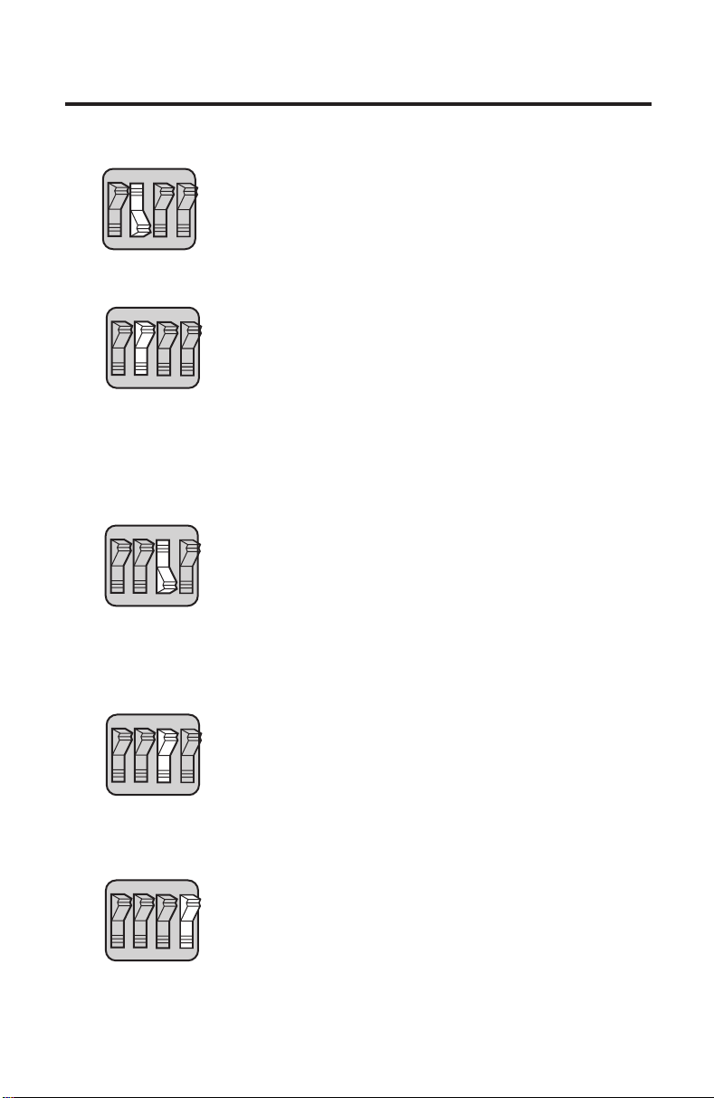
Pressing the FEED and PRINT buttons simultaneously causes a
test pattern to print. See Figure 45 (on page D-54).
1
2
Test Patter n
The test pattern is used to confirm that the print head is functioning
properly. If any of the print head elements are not functioning, a white
line will appear vertically down the printout. A defect in the paper may
also cause white lines or light printing. Repeat the test pattern to confirm
any suspected printing problems. If paper advances but nothing prints
out, check to be sure the paper is inserted properly (see page C-48).
D-53
Appendix D
Page 58

Software Version
2
The test pattern also includes the software version for the MicroTymp2
Printer/Charger.
Normative Data Reference
3
The test pattern is followed by normative data for tympanometric
characteristics for both the original MicroTymp and MicroTymp2 Handle.
4
This is provided along with the test pattern for the convenience of the
user, not specifically as a functional check.
Handle Data
4
If the Handle is placed in the well as the test pattern is being printed,
the printer reads the status of the Handle and prints out the results.
DO NOT remove the handle while printing Handle data, or Handle data
will be incomplete. The encoded data are only significant to the Technical Service Department at Welch Allyn.
1
Test Pattern
2
Software Version
Figure 45
D-54
Normative Data Reference
3
4
Handle Data
Page 59

Appendix E
Service and W arranty Information
Service
Repair
Repair must be performed by authorized personnel. Failure to do so invalidates the MicroTymp2 warranty.
For customers in North America, please return instruments requiring service
to a Welch Allyn Technical Service Department listed below or to an authorized Welch Allyn distributor.
Technical Service Department Technical Service Department
Welch Allyn, Inc. Welch Allyn Canada Ltd.
4341 State Street Road 160 Matheson Blvd. East, Unit #2
Skaneateles Falls, NY 13153-0220 Mississauga, Ontario
U.S.A. CANADA L4Z 1V4
Telephone: 800-669-9771 or Telephone: 800-561-8797 (in Canada
315-685-4560 only) or 905-890-0004
Fax: 315-685-3361 Fax: 905-890-0008
For customers outside of North America, return your unit to a local,
authorized Welch Allyn distributor.
Appendix E
Recalibration
Welch Allyn recommends that the MicroTymp2 Handle be recalibrated
annually. Arrangements may be made by returning the MicroTymp2 registration card or by contacting Welch Allyn’s Technical Service Department or an
authorized Welch Allyn MicroTymp2 distributor. A moderate fee is charged for
recalibration.
The MicroTymp2 instrument warranty may be extended for up to three years
provided the Handle is returned each year for recalibration.
A monthly functional check using the MicroTest Cavity is recommended.
The Printer/Charger does not require recalibration.
E-55
Page 60

Warranty
MicroTymp2 Instrument
Welch Allyn Inc. warrants the MicroTymp 2 Handle and Printer/Charger
to be free of original defects in material and workmanship and to perform in
accordance with manufacturer’s specifications for a period of one year from
the date of purchase. If this instrument or any component thereof is found to
be defective or at variance from the manufacturer’s specifications during the
warranty period, Welch Allyn will repair, replace or recalibrate the instrument
or component(s) at no cost to the purchaser.
This warranty only applies to instruments purchased new from Welch Allyn or
its authorized distributors or representatives. The purchaser must return the
instrument directly to Welch Allyn or an authorized MicroTymp2 distributor or
representative and bear the costs of shipping.
This warranty does not cover breakage or failure due to tampering, misuse,
neglect, accidents, modification or shipping, and is void if the instrument is
not used in accordance with manufacturer’s recommendations or if repaired
or serviced by other than Welch Allyn or a Welch Allyn authorized repr esentative.
Extend the MicroTymp2 warranty from one to three years.
This warranty can be extended to three years provided the MicroTymp2
Handle is returned to a Welch Allyn service location for recalibration annually.
A moderate fee for recalibration will be charged.
Purchase date determines warranty and annual recalibration requirements.
No other express or implied warranty is given.
NOTE: Return of the instrument registration card is required
for proof of purchase and warranty validation.
MicroTymp2 Rechargeable Battery
Welch Allyn nickel-cadmium batteries are warranted by Welch Allyn for two
years from date of manufacture (when used in Welch Allyn instruments only).
Defective batteries will be replaced on a pro rata basis should failure occur
prior to expiration date on battery.
E-56
Page 61

Appendix F
Technical Specifications
3.68 in
9.35 cm
7.32 in
18.6 cm
1.94 in
4.94 cm
Appendix F
1.0
0.5
Ya - mmho
0
-400 -200 0 200
PRESSURE - DaPa
RLTEST
2
GR
A
1
GR
B
+200 Vea - cc
9.70 in
24.6 cm
Figure 46
F-57
9.62 in
24.4 cm
POWER
CHARGE FEED PRINT
4.82 in
12.2 cm
Page 62

Probe Tone:
Frequency: 226 Hz ±3%
Amplitude: 85 ±3 dB re 20 µPa in an ANSI HA-1 (2.0 cc) coupler
Distortion: 5% maximum total harmonic distortion in an ANSI HA-1
(2.0 cc) coupler
Pump:
Direction of sweep: positive to negative pressure
Speed: 400 ±40 daPa/s average during data acquisition period
Pressure Measurement System:
Range: +200 to -400 daPa
Display resolution: 20 daPa
Accuracy: ±15% or ±10 daPa, whichever is greater
Compensation: Auto-zero every test cycle
Admittance Measurement System:
Range: 0.2 to 4.0 mmho total
0.0 to 1.5 mmho for Ya
0.2 to 2.5 cc for +200 Vea
Display resolution: 0.1 mmho for Ya
0.2 cc for +200 Vea
Accuracy: ±0.1 mmho or ±5%, whichever is greater
Weight:
MicroTymp2 Handle: 0.61 lb/0.28 kg
Printer/Charger: 3.98 lb/1.81 kg
Operating Temperature:
15˚ to 35˚C (59˚ to 95˚F). All specifications apply within this
temperature range.
Storage Temperature:
-20˚ to +40˚C (-4˚ to +104˚F)
Battery (Welch Allyn #72900):
2.4 V nickel-cadmium rechargeable, 14-16 hour recharge time
Full charge yields at least 300 double-ear tympanograms or approximately
one full day of continuous use
Probe Tips:
Four color-coded sizes
F-58
Page 63

Printer Paper (Welch Allyn #56100):
4.42" (112 mm) wide with core
Pink end-of-roll indicator
Approximate number of printouts per roll:
200 – Tympanogram, Data, and Messages reports
250 – Tympanogram and Data reports
300 – Tympanogram Only reports
Table 8 – MicroTymp2 Printer/Chargers
Welch Allyn Nominal Major Geographic Plug Type
Model Number Input Areas
Appendix F
71170 120 V~, 1A
71172 230 V~, 1A Europe
71174 230 V~, 1A United Kingdom
71176 230 V~, 1A
Operating Ranges:
Input voltage for all Printer/Charger models is 100 to 240 V~
Input frequency for all Printer/Charger models is 50 to 60 Hz
Input current is 1A maximum
Canada, Japan,
United States
Australia,
New Zealand
F-59
Page 64

Standards Compliance
ETL listed to comply with UL 2601
ETL listed to compy with CSA C22.2 No. 601-1
ETL listed to comply with IEC 601-1, Amendment 1
MicroTymp2 Handle:
Class I Equipment, Type BF
MicroTymp2 Printer/Charger:
Class I Equipment, Type B
FCC Part 15, Class A
This device complies with CFR 47 Part 15 Class A of the FCC rules.
Operation is subject to the following two conditions:
(1) This device may not cause harmful interference, and
(2) This device must accept any interference received, including
interference that may cause undesired operation.
CBC C108.8 M1983, Class A
This digital apparatus does not exceed the Class-A limits for radio
noise emissions from digital apparatus set out in the Radio Interference Regulations of the Canadian Department of Communications.
The CE mark on this device indicates it has been tested
to and conforms with the provisions noted within the
0050
Authorized European Representative Address:
European Regulatory Manager
Welch Allyn, Ltd.,
Kells Road, Navan,
County Meath,
Republic of Ireland
Tel. 353 46 28122
Fax 353 46 28536
This instrument complies with the following standards based on the most
recent revision available at the time of design:
American National Standard for Instruments to Measure Aural Acoustic
Impedance and Admittance — Aural Acoustic Immittance; ANSI S.391987 (ASA 71-1987)
IEC — Instruments for the Measurement of Aural Acoustic Impedance/
Admittance; IEC 1027:1991
93/42/EEC Medical Device Directive.
ANSI Type 4 instrument
IEC Type 4 instrument
F-60
Page 65

Appendix G
MicroTymp2 Replacement
Parts and Accessories
MADE EXCLUSIVELY FOR
USE ONLY SPECIFIED CHARGER
RECHARGEABLE BATTERY 2.4 VOLTS 600mAh
CATALOG NO. 72900
2.0 cc
MicroTest
CAVITY
0.5 cc
#23621 #23622 #23623 #23624
(White) (Black) (Gray) (Blue)
Small Medium Large Extra-
Large
Battery
#72900 2.4 V
Nickel-Cadmium Battery
Screw for Battery Cover
#236081
Screw Driver for
Battery Cover
#236200
MicroTest Cavity
#711772-501
Probe Tips
#23630 Set of 4 Tips
#711760-502 Tip Box Only
#711780-501 Tip Box with two
sets of tips
Appendix G
G-61
#23639 Multi-pack of Tips
(5 small,
10 medium,
10 large and
5 extra-large)
MicroTymp2 Paper
#56100 5 Rolls/Box,
12 Boxes/Case
Spindle for Paper
#761050-1
Page 66

Replacement Power Cords
#761076-0
120 V, Canada,
Japan, U.S.
#761076-4
230 V, United
Kingdom
2
GR
1.0
A
1
0.5
GR
Ya - mmho
B
+200 Vea - cc
0
-400 -200 0 200
PRESSURE - DaPa
RLTEST
#761076-2
230 V, Europe
#761076-6
230 V, Australia,
New Zealand
#23640
Handle
Carrying Case
for MicroTymp2
and AudioScope3
(#05276)
G-62
Page 67

References
American National Standards Institute (1987). “Specifications for Instruments
to Measure Aural Acoustic Impedance and Admittance (Aural Acoustic
Immittance).” New York: ANSI. ANSI S3.39-1987 (ASA71-1987).
American Speech-Language-Hearing Association (1985). “Guidelines for
Identification Audiometry.” ASHA, 27, 49-52, May, 1985.
American Speech-Language-Hearing Association (1990). “Guidelines for
Screening for Hearing Impairments and Middle Ear Disorders.” ASHA 32
(Suppl. 2): 17-24 (1990).
Bak, David J. (1988). “Microelectronics and a Tiny Pump Make Ear Exams
Easy.” Design News, February 15, 1988.
de Melker, Ruut (1992). “Diagnostic value of microtympanometry in primary
care.” British Medical Journal, Volume 304: 96-8 (1992).
Goodhill, V. (1979). Ear: Diseases, Deafness, and Dizziness. Maryland:
Harper and Row.
Holte, L., Cavanaugh, R.M. Jr., Margolis, R.H. (1990). “Ear canal wall mobility
and typanometric shape in young infants.” The Journal of Pediatrics, Volume
117, Number 1, Part 1: 77-80, July, 1990.
Holte, L., Margolis, R.H., Cavanaugh, R.M. (1991). “Developmental Changes
in Multifrequency Tympanograms.” Audiology, 30:1, 1-24, 1991.
International Electrotechnical Commission (1991). “Instruments for the
Measurement of Aural Acoustic Impedance/Admittance.” Dublin, Ireland:
IEC 1027:1991.
Lous, Jorgen (1989). “Eustachian Tube Dysfunction In Children, A comparison between MicroTymp and Middle Ear Analyzer 1722.” Proceedings of a
Conference on the Eustachian Tube and Middle Ear Diseases, Geneva,
Switzerland, October 26-29, 1989.
Margolis, R. H. (1981). “Fundamentals of Acoustic Immittance.” In G. R.
Popelka (ed.) Hearing Assessment with the Acoustic Reflex. New York:
Grune and Stratton.
Margolis, R. H., Heller, J. (1987). “Screening tympanometry: criteria for
medical referral.” Audiology, 26:197-208, 1987.
Margolis, R. H., Shanks, J. E. (1991). “Tympanometry: Basic Principles and
Clinical Applications.” In Wm Rintelmann (ed.) Hearing Assessment (2nd ed.).
Austin, TX: Pro-ed, Inc., 1991.
Occupational Safety and Health Administration (1991). “Occupational
Exposure to Bloodborne Pathogens; Final Rule.” Federal Register, Vol. 56,
No. 235, 29 CFR Part 1910.1030, 64175-64182, December, 1991.
63164
References
Page 68

Occupational Safety and Health Administration (1992). “Occupational
Exposure to Bloodborne Pathogens.” OSHA 3127, 1992.
Terkildsen, K., Thomsen, K. A., (1959). “The influence of pressure variations
on the impedance of the human eardrum.” J. Laryngol. Otol. 73:409-418.
U.S. Department of Health and Human Services (1994). “Managing Otitis
Media with Effusion in Young Children.” AHCPR Publication No. 94-0623,
1994.
U.S. Department of Health and Human Services (1994). “Otitis Media with
Effusion in Young Children.” AHCPR Publication No. 94-0622, 1994.
Van Camp, K. J., Margolis, R. H., Wilson, R. H., Creten, W., Shanks, J. E.
(1986). “Principles of Tympanometry.” ASHA Monographs. 24. Maryland:
American Speech-Language-Hearing Association.
Wazen, Jack J.; Ferraro, Judith A.; Hughes, Robert (1988). “Clinical
Evaluation of a Portable, Cordless, Hand-held Middle Ear Analyzer.”
Otolaryngology — Head and Neck Surgery, Volume 99, No. 3:348 - 350.
Page 69

Glossary
acoustic admittance (Ya) The ease with which acoustic energy is trans-
ferred into a system; the ratio of volume velocity to sound pressure.
acoustic millimho (mmho) The unit of acoustic admittance;
1 mmho = 10
aural acoustic immittance A term used to refer to aural acoustic admit-
tance, acoustic impedance, or any of their components.
cholesteatoma See keratoma.
compensated static acoustic admittance (Ya, Ytm) The admittance
of the middle ear at the air pressure corresponding to the tympanometric
peak. It is calculated by subtracting the admittance of the ear canal from
the admittance at the tympanometric peak. The MicroTymp2 estimates
compensated admittance by subtracting the admittance at +200 daPa from
the peak admittance.
decapascal (daPa) The unit of air pressure used for tympanometric measurements. 1 daPa = 1.04 mm H
equivalent ear canal volume (+200 Vea) The volume of air that has the
same acoustic admittance as the ear canal/middle ear system when the ear
is pressurized. The MicroTymp2 Handle measures Vea with a 226-Hz probe
tone and an ear canal air pressure of +200 daPa. Under these conditions,
Vea is a good estimate of the volume of air in front of the probe. Vea is
abnormally large in some patients with ear drum perforations and patent
tympanostomy tubes.
keratoma A collection of keratinizing squamous epithelium that invades the
middle ear; keratoma frequently originates from a perforation in Shrapnell’s
membrane (pars flaccida) of the tympanic membrane; also called
cholesteatoma.
-8 m3
/Pa s.
0.
2
lateral ossicular fixation Fixation of the malleus and/or incus, frequently
caused by tympanosclerosis, a complication of chronic otitis media.
middle ear effusion An accumulation of fluid (liquid) in the middle ear.
neomembrane A scar on the tympanic membrane; the scarred region may
be thinner and have a higher admittance than the normal tympanic membrane; also called monomere.
otalgia Ear ache or pain.
otitis media with effusion Inflammation of the middle ear, often accompa-
nied by an accumulation of fluid (liquid).
B-365
Glossary
Page 70

otorrhea External ear discharge.
otosclerosis A genetic abnormality of the temporal bone, frequently causing
fixation of the stapes and conductive hearing loss.
sound pressure The average (rms) difference between the air pressure that
occurs during sound transmission and the ambient air pressure.
tympanogram A recording of the admittance of the ear as a function of ear
canal air pressure.
tympanometric gradient See tympanometric width.
tympanometric peak pressure The value of ear canal air pressure at which
the tympanometric peak occurs.
tympanometric width A measure of the shape of the tympanogram in the
region of the tympanometric peak. Defined as the width of the tympanogram
(in decapascals) at 50% of peak eardrum admittance, tympanometric width
is a good indicator of the presence of middle ear effusion.
tympanometry The measurement of acoustic admittance in the sealed ear
canal as a function of ear canal air pressure.
tympanosclerosis A complication of otitis media that is characterized by
sclerotic regions involving the tympanic membrane, ossicles, and middle ear
mucosa. Tympanosclerosis increases the stiffness of the middle ear system.
volume velocity The volume of air that passes through a plane per unit time.
66
Page 71

Page 72

TM
Welch Allyn, Inc.
4341 State Street Road
P.O. Box 220
Skaneateles Falls,
New York 13153-0220
U.S.A.
Tel.: 800-535-6663 (U.S.A. only)
315-685-4560
Printed in U.S.A. Part No. 236311-2
Fax.: 315-685-3361
 Loading...